Table of Contents
Advertisement
Quick Links
Q
UICK
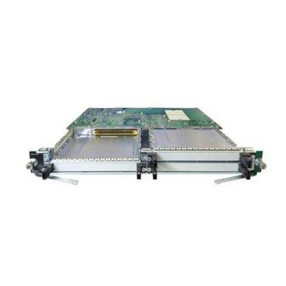
Cabling the Cisco uBR10-MC5X20S/U/H Cable
Interface Line Card with Universal Cable
Holder—UCH2
Last Updated: May 14, 2009
OL-24878-01
Contents
This document contains the following information:
•
•
•
•
•
•
•
Americas Headquarters:
Cisco Systems, Inc., 170 West Tasman Drive, San Jose, CA 95134-1706 USA
S
G
TART
UIDE
Feature Description
Installing the Cables
Installing the UCH
Removing the UCH
Removing the Cables
Troubleshooting
Related Documentation
Advertisement
Table of Contents

Related Manuals for Cisco uBR10-MC5X20H


Summary of Contents for Cisco uBR10-MC5X20H
- Page 1 This document contains the following information: Feature Description • Installing the Cables • Installing the UCH • Removing the UCH • • Removing the Cables • Troubleshooting • Related Documentation Americas Headquarters: Cisco Systems, Inc., 170 West Tasman Drive, San Jose, CA 95134-1706 USA UIDE...
-
Page 2: Feature Description
Cisco part number CAB-RFSW520QTIMF2. Note In European markets only, you must use the quad-shielded cable kit with the Cisco uBR10-MC5X20H. Cabling the Cisco uBR10-MC5X20S/U/H Cable Interface Line Card with Universal Cable Holder—UCH2 Cisco uBR10-MC5X20S/U/H Cards... - Page 3 Figure 2 shows the cable bundle for Cisco uBR10-MC5X20S/U/H cable interface line card to hybrid fiber-coaxial (HFC) plant that has 25 F connectors attached to one end and three UCH2 units attached to the other end. This cable is 9.84 feet (3 m) long and the part number is CAB-RFSW520QTIMF2. Figure 2 F Connectors Figure 3...
-
Page 4: Installing The Cables
Installing the Cables RF Switch Header Blocks Figure 4 shows the cable bundle for RF switch to HFC plant that has two RF switch header blocks attached to one end and 25 F connectors attached to the other end. This cable is 9.84 feet (3 m) long and the part number is CAB-RFSW520QTPMF2. - Page 5 Remove the ESD cap from a cable, and insert it into the hole in the UCH2. See Step 2 We recommend that the cables be installed in the UCH as shown in Caution If using quad-shielded cables, make sure there is no heat-shrink wrap on the ends by the MCX connectors.
- Page 6 Installing the UCH Table 2 Universal Cable Holder (1) Line Card Cable RF Switch Port Color User Defined Blue Green Yellow 1. US = upstream 2. DS = downstream Insert the cable completely into the UCH. (The cables will fit loosely in the holes until the lock bar is Step 3 closed in Step...
- Page 7 Position the UCH2 so the red line is on the same side as the red triangle on the faceplate. Step 4 Figure 6 Red line Cutout Lead screw Align the end pins with the pin holes in the faceplate, and guide the UCH onto the faceplate. Step 5 Hold the cables and UCH in place while finger tightening the leadscrew.
-
Page 8: Removing The Cables
Removing the Cables Figure 7 1/4 in. flathead screwdriver Removing the Cables Use the T-10 TORX driver tool to loosen the lock bar on the side you want to remove cables. Step 1 Slide the lock bar open by hand, or with a flathead screwdriver if the bar is stuck or hard to access. See Step 2 Figure (Make sure the lock bar is completely open or the cables will not release.) -
Page 9: Troubleshooting
Contact Cisco TAC for further information: http://www.cisco.com/tac Tool Manufacturers and Part Numbers Table 3 Cisco Systems Cable bundle for RF card to HFC plant: 3 UCH2 units attached to one end and F connectors attached to the other end, 9.84 feet (3 m) long. -
Page 10: Related Documentation
Any use of actual IP addresses or phone numbers in illustrative content is unintentional and coincidental. © 2009 Cisco Systems, Inc. All rights reserved. Cabling the Cisco uBR10-MC5X20S/U/H Cable Interface Line Card with Universal Cable Holder—UCH2 Tool Part Numbers (continued) “Related Documentation <required for IOS - optional for other>”...