Advertisement
Quick Links
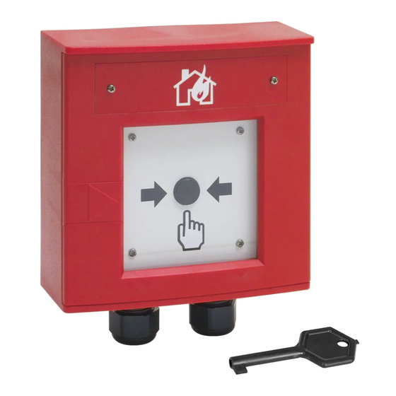
Installationsanleitung
Handfeuermelder (PAM)
Installation Instruction
Manual Call Point (IFD)
(Art.-Nr. / Part No. 761694)
Technische Änderungen vorbehalten!
798954
Technical changes reserved!
D
GB
01.2014 / AA
© 2014 Honeywell International Inc.
Novar GmbH a Honeywell Company
Dieselstraße 2, D-41469 Neuss
Internet: www.esser-systems.com
E-Mail: info@esser-systems.com
D
Achtung!
Diese Anleitung ist vor der Inbetriebnahme genau durchzulesen. Bei Schäden die durch Nichtbeachtung dieser
Installationsnleitung verursacht werden, erlischt der Gewährleistungsanspruch. Für Folgeschäden, die daraus
resultieren, wird keine Haftung übernommen.
Sicherheitshinweise
Den Melder NICHT an einer 230 V AC Nennspannung und nur im vorgesehenen Temperaturbereich
betreiben.
Die Wartung und Reparatur des Handfeuermelders darf nur durch eine Fachkraft erfolgen, die mit den damit
verbundenen Gefahren und Vorschriften vertraut ist.
Die Veränderung oder ein Umbau des Melders ist nicht zulässig.
Allgemein / Anwendung
Der Handfeuermelder mit Schutzart IP 66 wird zur manuellen Auslösung eines Brandalarmes bzw. einer
Gefahrenmeldung in feuchten Räumen oder im Freien eingesetzt
Bedienung
Bei Servicearbeiten die evtl. vorhandene Alarmweiterleitung, wie z. B. die unbeabsichtigte Auslösung einer
Alarmübertragungseinrichtung (AÜE) zu beachten.
Durch Wenden des Beschriftungsfeldes
12
kann die Kennzeichnung des Handfeuermelders gewechselt
werden (siehe Abb. 2).
Auslösen:
Glasscheibe
einschlagen und Druckknopf
Zum Einstecken des Schlüssels die Schlüssellochabdeckung
Rückstellen:
Schlüssel auf den Stift (Abb. 4) aufstecken und mit einer leichten Drehung nach rechts den
Kunststoffhebel nach unten drücken, bis der Druckknopf wieder herausspringt.
Testbetrieb:
Meldertür
mit dem Schlüssel öffnen und den Druckknopf
Installation
Meldergehäuse mit dem beiliegenden Schlüssel öffnen, die vier Innensechskant-Schrauben
Einsatz entnehmen. Meldergehäuse an den beiden Befestigungspunkten
mit den beiliegenden Dübeln und Schrauben ohne mechanische Verspannung befestigen.
Melder gem. Abb. 6 anschalten. Dichtring
einsetzen und Einsatz wieder montieren. Die vier Innensechskant-
Schrauben
vorsichtig anziehen, dabei Drehmoment (max. 1,5 Nm) beachten!
Um die Schutzart IP 66 zu gewährleisten, Dichtigkeit des Meldergehäuses, der Kabeleinführungen /
Kabelverschraubungen
beachten.
Die Glasscheibe kann nach dem Öffnen der Tür durch leichten Druck auf den Haltestift
seitlichen Halterungen
entnommen bzw. wieder eingesetzt werden.
Zur Kennzeichnung des (noch) nicht betriebsbereiten Handfeuermelders sollte bis zur Inbetriebnahme das
beiliegende Hinweisschild
11
eingesetzt werden.
Anschaltung
Der Handfeuermelder wird als Busteilnehmer direkt an die Ringleitung der ESSER-Brandmelderzentralen
angeschlossen (Abb.6). . Der integrierte Leitungstrenner gewährleistet die Funktionstüchtigkeit der Anlage, falls
ein Segment der Ringleitung durch Kurzschluss ausfällt.
Verdrahtungsfolge der Ringleitung Klemmen beachten -UL(IN) -UL(OUT)! Fernmeldekabel
I-Y (St) Y n x 2 x 0,8 mm mit besonderer Kennzeichnung oder Brandmeldekabel verwenden! Durch den
Anschluss der Kabelabschirmung werden die Signalleitungen gegen Störeinflüsse geschützt.
§
Handfeuermelder und automatische Brandmelder dürfen gemäß den VdS-Richtlinien nicht auf einer
gemeinsamen Meldergruppe betrieben werden (max. 10 Handfeuermelder / Gruppe).
Ergänzende und aktuelle Informationen
Die Produktangaben entsprechen dem Stand der Drucklegung und können durch Produkt-änderungen,
geänderte Normen / Richtlinien ggf. von den hier genannten Informationen abweichen.
Aktualisierte Informationen, Konformitätserklärungen und Instandhaltungsvorgaben siehe
www.esser-systems.com.
Dokumentation der Brandmelderzentrale bzgl. Normen, lokalen Anforderungen und Systemvoraus-
setzungen beachten!
®
®
esserbus
und essernet
sind in Deutschland eingetragene Warenzeichen.
Technische Daten
Betriebsspannung
:
8 V DC bis 42 V DC
Ruhestrom
:
ca. 45 µA @ 19 V DC
Alarmstrom
:
ca. 9 mA @ 19 V DC, gepulst
Melderzahl
:
max. 127 Melder (pro Ringleitung)
Anschlussklemmen
:
max. 1,5 mm² (AWG 30-14)
Umgebungstemperatur
:
-20 °C bis +70 °C
Lagertemperatur
:
-25 °C bis +75 °C
Schutzart
:
IP 66
Gehäuse
:
PC-Kunststoff, rot (ähnlich RAL 3000)
Gewicht
:
ca. 475 g
Maße (B x H x T)
:
135 x 135 x 61 (mm)
Spezifikation
:
EN 54-11 : 2001 / A1 : 2005 / -17 : 2005, Typ B
VdS-Anerkennung
:
G 209190
Leistungserklärung
:
DoP-20882130701
Warning!
Please study these manual carefully before commissioning. Failure to observe this instruction voids the product
warranty. We cannot accept any liability for any consequential damage resulting from such improper operation
or installation.
Safety information
Do NOT connect the call point to a 230 V AC power source, and operate it only within the intended
temperature range.
Maintenance and repairs may only be performed by properly qualified personnel familiar with the hazards
and applicable regulations.
Do not modify the call point unit in any way. Doing so voids the warranty.
General / Application
The manual call point with protection rating IP 66 is used to manually trigger a fire or hazard alarm in humid
rooms or open areas.
Operation
The alarm activation and triggering of notifying systems e. g. manned centre link (Master box) must be
observed during any service.
The labelling of the MCP may be altered by turning around the text field
Trigger Alarm:
bis zum Einrasten tief drücken.
öffnen (Abb. 2).
Reset:
Test mode:
bis zum Einrasten tief drücken.
Installation
lösen und
Open enclosure with the supplied key, release all four hexagon screws
auf einer geeigneten Wandfläche
The Detector housing must be fixed at both fixing points
and screws without mechanical stress.
Connect the call point as shown in Fig. 6. Insert the gasket
hex socket-head screws
Observe the tightness of the enclosure, threaded cable entries
The glass cover may be removed or inserted into the sideway fasteners
aus den beiden
of the front door.
To indicate that the detector is out of operation it is recommended to insert the delivered label
commissioning is done and the detector may be operated.
Wiring
The Manual Call Point must be connected to the ESSER-Fire Alarm Control Panel via the loop (Fig. 6). The
integrated loop isolator provides the operation in case of a short circuit on the loop.
§
Specifications
Operation voltage
Quiescent current
Alarm current
Number of detectors
Terminals
Ambient temperature
Storage temperature
Protection rating
Housing
Weight
Dimensions (w x h x d)
Specification
VdS approval
Declaration of Performance
GB
Break the glass
and press the button
until it engages.
Open the keyhole cover
to insert the key (Fig. 2)
Place key on the bolt (Fig. 4) and turn it carefully clockwise until the plastic tab moves
downwards and the button is released.
Open the enclosure
by using the key
and press the button
mounted on a suited wall using the delivered dowels
and refit the inlay. Carefully tighten the four
to a maximum torque of 1.5 Nm!
to ensure the higher IP66 protection rating.
Observe the wiring sequence of the loop terminal -UL(IN) -UL(OUT).
Use cable I-Y (St) Y n x 2 x 0.8 mm with suited specification or fire detection cable! The cable
shielding must be connected to provide EMC protection!
According to the VdS-Guidelines (VdS, German Insurance Association), it is not allowed to install
automatic detectors and manual call points in one zone (max 10 MCP per zone).
Additional and updated Information
The product specification relate to the date of issue and may differ due to modifications and/or
amended Standards and Regulations from the given informations.
For updated information, declaration of conformity and maintenance specifications please refer to
www.esser-systems.com.
Always follow the documentation for the fire alarm control panel with regard to standards, local
requirements and system prerequisites!
®
®
esserbus
and essernet
are registered trademarks in Germany.
8 V DC to 42 V DC
:
approx. 45 µA @ 19 V DC
:
: approx. 9 mA @ 19 V DC, pulsed
:
max. 127 detectors (per loop)
max. 1,5 mm² (AWG 30-14)
:
-20 °C to +70 °C
:
-25 °C to +75 °C
:
: IP 66
PC plastic, red (similar to RAL 3000)
:
approx. 475 g
:
135 x 135 x 61 (mm)
:
:
EN 54-11 : 2001 / A1 : 2005 / -17 : 2005, type B
:
G 209190
:
DoP-20882130701
12
(refer to fig. 2).
until it engages.
and remove inlay.
by briefly pressing the spring lock
11
until the
Advertisement

Related Manuals for Honeywell ESSER 761694


Summary of Contents for Honeywell ESSER 761694
- Page 1 The glass cover may be removed or inserted into the sideway fasteners by briefly pressing the spring lock 01.2014 / AA © 2014 Honeywell International Inc. Die Glasscheibe kann nach dem Öffnen der Tür durch leichten Druck auf den Haltestift aus den beiden ...
- Page 2 Feuerwehr oder / or 112,5 Abb. 1 / Fig. 1 Abb. 2 / Fig. 2 Out of Außer Order Betrieb Abb. 3 / Fig. 3 Abb. 4 / Fig. 4 Abb. 5 / Fig. 5 Ringmodul Loop module +UL / B+ / B- Legende 1 = -UL...