Advertisement
Quick Links
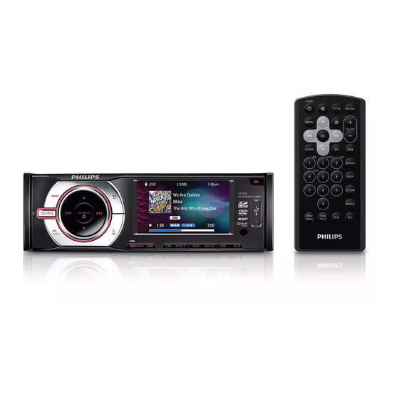
Car Audio Video System
TABLE OF CONTENTS
Location of PCBS......... .....................1-1
Specifications......... ............... ............1-2
Safety Instruction, Warning & Notes ......1-3
Disassembly diagram......... ... ............2-1/2
Software version check&upgrade..........3-1
Malfunction check chart...... ......... ... . . . 3-2
Wiring diagram... ............ ..................4-1
Main board-circuit diagram-1...............5-1
Main board-circuit diagram-2...............5-2
PCB layout top/bottom view ...............5-3
Servo board-circuit diagram-1 .......... ...6-1
©
Copyright 2011 Philips Consumer Electronics B.V. Eindhoven, The Netherlands
All rights reserved. No part of this publication may be reproduced, stored in a retrieval system or
transmitted, in any form or by any means, electronic, mechanical, photocopying, or otherwise without
the prior permission of Philips.
Published by DB- SL 1149 BG AVM
Version 1.3
Printed in The Netherlands
Subject to modification
Servo board-circuit diagram-2...............6-2
Layout diagram top/bottom view............6-3
SB+CB board-circuit diagram... .............7-1
SB+CB board-layout top/bottom vie w.......7-2
LB+SD
+CB
board-circuit diagram...........8-1
LB+SD+CB board-layout diagram............8-2
KEY board-circuit diagram...... .... . . .........9-1
KEY
board layout diagram ....................
Exploded view-main unit ........................... 10-1
CED229X/78
CED229/51/55/98
... .......9-2
CLASS 1
LASER PRODUCT
3141 785 35593
Advertisement

Related Manuals for Philips CED229/51


Summary of Contents for Philips CED229/51
- Page 1 LASER PRODUCT © Copyright 2011 Philips Consumer Electronics B.V. Eindhoven, The Netherlands All rights reserved. No part of this publication may be reproduced, stored in a retrieval system or transmitted, in any form or by any means, electronic, mechanical, photocopying, or otherwise without the prior permission of Philips.
- Page 2 X/78...
-
Page 4: Technical Specifications
• Specifications are indicative (subject to change). Technical Specifications For on-line product support please use the following website: http://www.p4c.philips.com/cgi-bin/dcbint/cpproduct_selector.pl Here is product information available, as well as getting started, user manuals, frequently asked questions and software & drivers. Directions for Use You can download this information from the following websites: http://www.philips.com/support... -
Page 5: Safety Instructions
Make sure that, • Use only lead-free soldering tin Philips SAC305 with order during repair, you are connected with the same potential as code 0622 149 00106. If lead-free solder paste is required, the mass of the set by a wristband with resistance. - Page 6 1 - 6 Safety Instructions, Warnings, Notes, and Abbreviation List 2.3.5 Alternative BOM identification Abbreviation List It should be noted that on the European Service website, 0/6/12 SCART switch control signal on A/V “Alternative BOM” is referred to as “Design variant”. board.
- Page 7 Electro Magnetic Interference LORE LOcal REgression approximation EPLD Erasable Programmable Logic Device noise reduction Europe LG.Philips LCD (supplier) EXTernal (source), entering the set by Loudspeaker SCART or by cinches (jacks) LVDS Low Voltage Differential Signalling Fast BLanking: DC signal Mbps...
- Page 8 4.406250 MHz and 4.250000 MHz Sound Intermediate Frequency SMPS Switched Mode Power Supply System on Chip Sync On Green SOPS Self Oscillating Power Supply S/PDIF Sony Philips Digital InterFace SRAM Static RAM Service Reference Protocol Small Signal Board STBY STand-BY SVGA 800x600 (4:3)
- Page 25 Remark: Pos. No. 14 Key Board Ass’y cannot be ordered seperately and must be ordered with whole Front Panel Ass’y (Pos. No. 101)