Table of Contents
Advertisement
Quick Links
Thank you for your purchase of the Aicure LED spot UV curing system.
■ In order to use the system correctly, please read this User's Manual carefully before use.
After you have read it, store it in a secure location, and refer back to it if you have any
uncertainties.
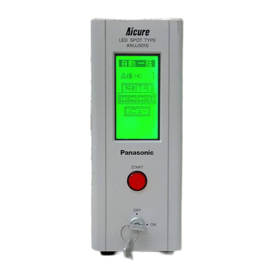
Aicure UV Curing System
ANUJ5010
User's Manual
Advertisement
Table of Contents

Related Manuals for Panasonic ANUJ5010


Summary of Contents for Panasonic ANUJ5010
- Page 1 ANUJ5010 Aicure UV Curing System User’s Manual Thank you for your purchase of the Aicure LED spot UV curing system. ■ In order to use the system correctly, please read this User's Manual carefully before use. After you have read it, store it in a secure location, and refer back to it if you have any...
- Page 2 LED Product Safety Precautions LED Product Classification The light source of the LED head connected to this product is classified as 3B under the JIS C6802 “LED Product Safety Standard.” Wavelength: 365 ±5 nm Max output: 150 mW Class 3B LED Product JIS C6802: 2005 Controlling or calibrating this product by other than the procedures stipulated here could cause exposure to dangerous LED radiation.
- Page 3 Safety Measures for LED Products Equipment This product provides the following equipment, in accordance with JIS C6802, “Radiation Safety Standards for LED Products.” ■ Remote Interlock Connector UV radiation can be halted by freeing the emergency stop input terminals (23-24) at the rear of the controller.
- Page 4 Safety Measures for LED Products Labels The LED head ships from the factory with the following LED radiation warning labels stipulated by JIS C6802 affixed. Also, Chinese warning labels for the GB standard and English warning labels for the IEC/EN standard are included. ■...
- Page 5 Safety Precautions The purpose of these cautions is to enable you to use this product safely and correctly, to prevent injury or loss to yourself and others. In order to explicitly indicate the severity and likelihood of damage and/or injury, likely errors are denoted with the terms “Danger” or “Warning.” Both of these are vital for ensuring safety.
- Page 6 Cautions for Use Do not connect the system to a power supply outside the rated voltage/frequency range listed on the system or in this manual. Doing so could cause it to become damaged. Please use the system within the ambient conditions listed below. Using under other than the indicated conditions could shorten the system lifetime.
-
Page 7: Table Of Contents
Contents 1 Features of the ANUJ5010 Aicure......1 8 Irradiation Data Display ........22 2 Product Components..........3 9 Configuration ............23 9.1 Fine Tuning the LED Head....... 23 3 Name and Function of Each Part......4 9.2 Configuring the Irradiation Patterns ....24 Front/Back............ -
Page 9: Features Of The Anuj5010 Aicure
1 Features of the ANUJ5010 Aicure The ANUJ5010 Aicure is an UV curing system that quickly hardens UV resins (inks, adhesives, and coatings) via irradiation with UV light from an LED light source. Focused irradiation of UV resins coated on minute surfaces (2 to 3 mm dia.) such as the lenses of CD, MD, and DVD players, and the LCD panels of notebook PCs and the like, with UV radiation enables precise adhesion. - Page 10 Features of the ANUP5010 Aicure ■ Easy operation via touch panel Perform setup and operation via a touch panel on the front of the unit. The LED status is displayed during UV irradiation. ■ Wide range of safety features The system is equipped with features to sense overcurrent and breaks in the LED head cord. If the LED becomes abnormally overheated, due to an ambient temperature increase or the like, it automatically turns off.
-
Page 11: Product Components
Optional components (sold separately) Head with lens ANUJ6324 head with lens unit ANUJ61324 ANUJ6325 head with lens unit ANUJ61325 Head alone Head for ANUJ5010 ANUJ6130 Lens unit 4 mm (dia.) replacement lens ANUJ6324 5 mm (dia.) replacement lens ANUJ6325 Connection cable 1.7 m flexible cable... -
Page 12: Name And Function Of Each Part
3 Name and Function of Each Part Front Touch Panel START button Key power switch Back Connection cord terminals External input terminals UV radiation emergency stop terminals Fuse holder Power socket (100–240 VAC 50/60Hz) -
Page 13: Touch Panel
Name and Function of Each Part Touch Panel Touch MENU to display the Menu screen To Auto Mode screen: Monitor auto operation and check irradiation status. (see p. 16) To Manual Mode screen: Perform manual operation and check irradiation status. (see p. - Page 14 Name and Function of Each Part ■ ANUJ5010 Aicure Operation Modes The ANUJ5010 Aicure has the following operation modes. Manual Mode On the Menu screen, touch MANUAL to operate from the Manual Mode screen. • Press the START button on the main unit to begin irradiation. Press the START button again to stop it.
- Page 15 Name and Function of Each Part Auto Batch Status Start Mode On the Menu screen, ensure that ALL/STAT are inverted. Touch Auto to operate from the Auto Mode screen. • When the main unit is in READY status, changing the external START 1 signal from “off” to “on” (during auto irradiation, it is always on) initiates batch irradiation of the LEDs selected for this model.
- Page 16 Name and Function of Each Part ■ Switching Menu Screens The menu screens are switched as follows.
- Page 17 Name and Function of Each Part ■ The Setup Sequence The sequence required to configure the ANUJ5010 Aicure for use is described below. Turn on Power Plug the power cord into the main unit. Plug the connection cable into the main unit.
- Page 18 Name and Function of Each Part Auto Mode Operation Touch AUTO to change to the Auto Mode screen. Make sure that READY is displayed, and start irradiation. Irradiation can be started via an external signal or the START button on the main unit. The START button on the main unit initiates batch irradiation.
-
Page 19: Installation
4 Installation Install the ANUJ5010 Aicure under the conditions below. 4.1 Installation Conditions 1) Ambient temp.: Main unit: 10 to 40 Head: 5 C to 35 2) Relative humidity: No greater than 85%, with no condensation 3) Make sure the rubber legs are set horizontally parallel. -
Page 20: Getting Started
5 Getting Started After connecting the necessary cords, lastly plug in the power cord. This section describes the steps up to turning on the power. 5.1 Hooking up the Connection Cable Remove the caps on the connection-cable terminals, and hook up the cables. - Page 21 Getting Started Rear Panel Procedure Remove the protective cap on the main unit Plug in the connection cable. Plug the connection cable into the LED head. Remove the protective cap on the LED head. Warning Note: The LED head is made of aluminum. Care is required, because if you tighten it Set the LED jig in place.
-
Page 22: Connecting The External Control Signals
Getting Started 5.3 Connecting the External Control Signals The external-control connectors on the back of the main unit (two banks of 12 pins) are removable. It is possible to loosen the M3 screw on either side, remove the connector board, mount the crimping terminals, and mount it on the rear of the main unit. -
Page 23: Connecting The Power Supply
Getting Started 5.4 Connecting the Power Supply Plug the supplied power cord into the power socket at the back of the main unit. After setting up the main unit, plug the power cord into the power outlet. The supplied power cord has a three-pronged plug. It must Warning be plugged into an earthed (three-prong) power outlet. -
Page 24: Operation Modes
6 Operation Modes 6.1 Auto Mode Do display the Auto Mode screen, touch MENU→ AUTO. ■ Checking Status The Auto Mode screen consists of the following elements: Current Auto Mode settings AUTO ALL The model setting TYPE NO. The status of the main unit (will be either READY, READY NO LED, or LED ON) The LED status (inverted: connected;... -
Page 25: Auto Mode Settings
Operation Modes ■ Auto Mode Settings When operating the ANUJ5010 Aicure via external control signals, select Auto Mode as shown below. From the touch-panel Menu screen, select and invert one of the buttons. Types of Start Signal Pulse Begin irradiation upon start of external signal. -
Page 26: Manual Mode
Operation Modes 6.2 Manual Mode Do display the Manual Mode screen, touch MENU→ MANUAL. ■ Checking Status The Manual screen consists of the following elements: READY The status of the main unit (will be either READY, NO LED, or LED ON) 1 2 3 4 The LED status (inverted: connected;... -
Page 27: Manual Irradiation
Operation Modes ■ Manual Irradiation Manually start and stop irradiation. The light modulation ratio and irradiation time can be changed at will. Configure them before irradiation. When performing manual irradiation, all selected LEDs Warning (those with inverted displays) perform batch irradiation. Individual irradiation is not available. -
Page 28: Changing/Setting Models
7 Changing/Setting Models Change or configure the model type for Auto Mode. On the ANUJ5010 Aicure, each of the 4 LED heads can be configured independently with 10 different irradiation patterns. Additionally, the combinations of irradiation-pattern settings of LEDs 1 to 4 can be saved as 10 different model types. -
Page 29: Setting Models
Changing/Setting Models ■ Setting Models Touch the number of the operation type to configure. Touch the down arrow (↓) to display numbers 7 through Touch TYPE SET to display the selected model screen. Touch the up and down arrows (↑/↓) to display the previous/next models in turn. -
Page 30: Irradiation Data Display
8 Irradiation Data Display Display the number of irradiations and cumulative irradiation time of the LEDs. Use this data as a rough guide to the irradiation count and when to replace the LED head. Do display the Data screen, touch MENU → DATA. Clear the counter. -
Page 31: Configuration
9 Configuration Use the Setup screens to fine-tune the LED heads, configure the irradiation patterns, etc. Do display the Setup screen, touch MENU → SETTING. Touch the buttons below to display their corresponding Setup screens. Head adjust: Fine-tune the LED head Pattern: Configure the irradiation patterns Busy signal: Change the busy-signal output contact Switch Language: Switch the UI language... -
Page 32: Configuring The Irradiation Patterns
Configuration 9.2 Configuring the Irradiation Patterns The ANUJ5010 Aicure can store up to 10 different LED irradiation patterns. The process from irradiation start to irradiation end can be divided into up to 10 steps, and the UV light modulation ratio (intensity) and irradiation time (time) can be set freely for each. -
Page 33: Changing The Signal Output Contacts During Irradiation
Configuration 9.3 Changing the Signal Output Contacts During Irradiation The busy signal can be changed from contact a output (initial setting) to contact b output. To display the Busy Signal Change screen, touch MENU → SETTING → BUSY SIG. Touch A CONTACT or B CONTACT. The touched setting is selected (inverted display). -
Page 34: Operation Via External Signals
10 Operation via External Signals 10.1 How the External Control Connector and Signals Work Pin layout of the external control connector (two banks of 12 pins) Signal Name Description READY Output Irradiation prep. status OK BUSY1 Output LED 1 irradiation ongoing ERROR Output Error signal... - Page 35 Operation via External Signals...
-
Page 36: Configuring The Irradiation Patterns
Operation via External Signals 10.2 Configuring the Irradiation Patterns ■ Batch Irradiation Ready Conditions (1) Make sure that the system is configured to irradiate the selected model. When the system is not configured for irradiation: None of LEDs 1 to 4 have a pattern selected (all are pattern 0). Also, if the time for step 1 is 0 seconds for each of the patterns selected for LEDs 1 to 4. - Page 37 Operation via External Signals Batch Pulse Status Time Chart Batch Status Status Time Chart...
- Page 38 Operation via External Signals ■ Individual Irradiation Ready Conditions (1) Make sure that the system is configured to irradiate the selected model. When the system is not configured for irradiation: None of LEDs 1 to 4 have a pattern selected (all are pattern 0). Also, if the time for step 1 is 0 seconds for each of the patterns selected for LEDs 1 to 4.
- Page 39 Operation via External Signals Individual Pulse Status Time Chart Individual Status Time Chart...
-
Page 40: Warning Messages
11 Warning Messages If an error occurs during irradiation, the Auto Mode screen and Manual Mode screen will display a warning message. ■ For Auto Mode Setup Screen The error message is classified by the temperature and time ranges. The inverted LED number(s) (1 to 4) indicates the location of the error. - Page 41 Warning Messages ■ LED Temperature Warning Screen When the temperature of the LED head exceeds the danger level, the amount over is displayed. ■ Replacement Time Warning Screen Shows the amount of time remaining to replace the LED head.
- Page 42 Warning Messages ■ Errors in LED Connections, etc. In the case of a system error, such as a data transmission error or LED connection error, the following Warning Screens (red) appear. Press RESET to cancel the setting. The screen turns back to green. Press and hold RESET to forcibly cancel.
-
Page 43: Safety Measures
12 Safety Measures 12.1 Safety Circuit The ANUJ5010 Aicure is equipped with a safety circuit in case of damage or accidents. If the cable between the LED head and main unit becomes severed, an error signal will be created, and the Error screen appears. -
Page 44: Specifications
13 Specifications Controller Model ANUJ5010 Operating power 100 to 240 V AC (±10%) 50/60 Hz 70 VA (at 100 V 100% output) Head Irradiation intensity 1,400 mW/cm 1,000 mW/cm Model With lens ANUJ61324C ANUJ61325C cable With lens ANUJ61324 ANUJ61325 Head alone... -
Page 45: Dimension Diagrams
14 Dimension Diagrams... -
Page 46: List Of Optional And Supplementary Parts
Optional Head with lens ANUJ6324 head with lens unit ANUJ61324 replacement parts ANUJ6325 head with lens unit ANUJ61325 Head alone Head for ANUJ5010 ANUJ6130 Lens unit 4 mm (dia.) replacement lens ANUJ6324 5 mm (dia.) replacement lens ANUJ6325 Connection cable 1.7 m flexible cable... -
Page 47: Troubleshooting
16 Troubleshooting Issue Checks/Remedies LED does not irradiate Is the time for step 1 of the LED pattern you have selected for irradiation in Model Setup set to 0 seconds? →If the time is set to 0 seconds, the system will exit without performing irradiation. -
Page 48: Manual Revision History
Manual Revision History Manual No. Issued Revision Details 2005/3 Initial version Although our manuals are prepared with great care, if you should spot any errors, please let us know at the address below: Matsushita Electric Works Machine & Vision, Ltd. 1048 Kadoma, Kadoma City, Osaka 571-8686 Japan TEL: +81-6-6903-5129 (main switchboard)