Table of Contents
Advertisement
Quick Links
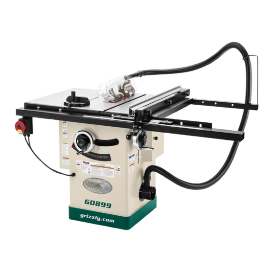
MODEL G0899
10" HYBRID TABLE SAW
w/RIVING KNIFE
OWNER'S MANUAL
(For models manufactured since 10/20)
601745
COPYRIGHT © DECEMBER, 2019 BY GRIZZLY INDUSTRIAL, INC., REVISED NOVEMBER, 2020 (MN)
WARNING: NO PORTION OF THIS MANUAL MAY BE REPRODUCED IN ANY SHAPE
OR FORM WITHOUT THE WRITTEN APPROVAL OF GRIZZLY INDUSTRIAL, INC.
#AI20510 PRINTED IN TAIWAN
V3.11.20
Advertisement
Table of Contents

Related Manuals for Grizzly G0899


Summary of Contents for Grizzly G0899
- Page 1 (For models manufactured since 10/20) 601745 COPYRIGHT © DECEMBER, 2019 BY GRIZZLY INDUSTRIAL, INC., REVISED NOVEMBER, 2020 (MN) WARNING: NO PORTION OF THIS MANUAL MAY BE REPRODUCED IN ANY SHAPE OR FORM WITHOUT THE WRITTEN APPROVAL OF GRIZZLY INDUSTRIAL, INC.
- Page 2 This manual provides critical safety instructions on the proper setup, operation, maintenance, and service of this machine/tool. Save this document, refer to it often, and use it to instruct other operators. Failure to read, understand and follow the instructions in this manual may result in fire or serious personal injury—including amputation, electrocution, or death.
-
Page 3: Table Of Contents
SECTION 1: SAFETY ........9 Safety Instructions for Machinery ....9 SECTION 6: AFTERMARKET Additional Safety for Table Saws ....11 ACCESSORIES FROM GRIZZLY ....58 Preventing Kickback ........12 SECTION 7: MAINTENANCE ......61 Protecting Yourself From Kickback....12 Schedule ............ -
Page 4: Introduction
ID label (see below). This information is required for us to provide proper tech support, and it helps us determine if updated documenta- tion is available for your machine. Manufacture Date Serial Number Model G0899 (Mfd. Since 10/20) -
Page 5: Identification
Keep hands out of the line of saw blade. d) Use a push-stick when required. e) Pay particular attention to instructions on reducing risk of kickback. f) Do not perform any operation freehand. g) Never reach around or over saw blade. Model G0899 (Mfd. Since 10/20) -
Page 6: Controls & Components
H. Fence Lock Knobs: Secure fence when Figure 1. Location of ON/STOP switch. tightened; allow fence to be repositioned along fence tube when loosened. Figure 3. Location of fence controls. Model G0899 (Mfd. Since 10/20) -
Page 7: Glossary Of Terms
The following is a list of common definitions, terms and phrases used throughout this manual as they relate to this table saw and woodworking in general. Become familiar with these terms for assembling, adjusting or operating this machine. Your safety is VERY important to us at Grizzly! Arbor: A metal shaft extending from the drive... -
Page 8: Machine Data Sheet
MACHINE DATA SHEET Customer Service #: (570) 546-9663 · To Order Call: (800) 523-4777 · Fax #: (800) 438-5901 MODEL G0899 10" HYBRID TABLE SAW WITH RIVING KNIFE Product Dimensions: Weight................................403 lbs. Width (side-to-side) x Depth (front-to-back) x Height................66 x 40 x 48 in. - Page 9 The information contained herein is deemed accurate as of 12/9/2020 and represents our most recent product specifications. Model G0899 PAGE 2 OF 3 Due to our ongoing improvement efforts, this information may not accurately describe items previously purchased. Model G0899 (Mfd. Since 10/20)
- Page 10 The information contained herein is deemed accurate as of 12/9/2020 and represents our most recent product specifications. Model G0899 PAGE 3 OF 3 Due to our ongoing improvement efforts, this information may not accurately describe items previously purchased. Model G0899 (Mfd. Since 10/20)
-
Page 11: Section 1: Safety
Never operate under the influence of drugs or injury or blindness from flying particles. Everyday alcohol, when tired, or when distracted. eyeglasses are NOT approved safety glasses. Model G0899 (Mfd. Since 10/20) - Page 12 Make sure they are properly installed, you experience difficulties performing the intend- undamaged, and working correctly BEFORE ed operation, stop using the machine! Contact our operating machine. Technical Support at (570) 546-9663. -10- Model G0899 (Mfd. Since 10/20)
-
Page 13: Additional Safety For Table Saws
DO NOT attempt dado or rabbeting operations covered wood products, and some plastics. Never without first reading these sections in this manual. cut materials not intended for this saw. -11- Model G0899 (Mfd. Since 10/20) -
Page 14: Preventing Kickback
Making a deep the flying stock, it is often the case that non-through cut will greatly increase the the operator’s hands are pulled into the chance of kickback. blade during kickback. -12- Model G0899 (Mfd. Since 10/20) -
Page 15: Section 2: Power Supply
Nominal Voltage ..208V, 220V, 230V, 240V Cycle ............60 Hz Phase ........... Single-Phase Circuit Rating ........15 Amps Plug/Receptacle ......NEMA 6-15 -13- Model G0899 (Mfd. Since 10/20) - Page 16 Additionally, it must 6-15 RECEPTACLE meet the following size requirements: Current Carrying Prongs Minimum Gauge Size ......12 AWG 6-15 PLUG Maximum Length (Shorter is Better)..50 ft. Grounding Pin Figure 5. Typical 6-15 plug and receptacle. -14- Model G0899 (Mfd. Since 10/20)
-
Page 17: Converting Voltage To 230V
Close and secure motor junction box. • Circuit Breaker 10A (P0899224X) ....1 Remove ON/STOP switch cover from switch To convert Model G0899 to 230V: box. DISCONNECT MACHINE FROM POWER! Replace pre-installed 20A circuit breaker (see Figure 8) with 10A circuit breaker (part Cut off existing 5-20 plug. -
Page 18: Section 3: Setup
IMPORTANT: Save all packaging materials until you are completely satisfied with the machine and have resolved any issues between Grizzly or the shipping agent. You MUST have the original pack- aging to file a freight claim. It is also extremely helpful if you need to return your machine later. -
Page 19: Inventory
⁄ " ....2 —Hex Nuts ⁄ " .......... 2 Hinge Pins ..........2 Z. Push Stick Hangar ........1 —Hex Nuts ⁄ "-20 ........2 —Flat Washers 5mm........2 Figure 11. Component inventory. -17- Model G0899 (Mfd. Since 10/20) - Page 20 BD. Hex Nut M6-1 (Dust Hose Support) ... 1 BE. Button Head Cap Screws M5-.8 x 12 (Dust Port) ..........4 BF. Flat Washers 6mm (Dust Port) ....4 BG. Lock Washer 6mm (Dust Hose Support) ..1 -18- Model G0899 (Mfd. Since 10/20)
-
Page 21: Hardware Recognition Chart
Hardware Recognition Chart USE THIS CHART TO MATCH UP HARDWARE DURING THE INVENTORY AND ASSEMBLY PROCESS. Flat Head Screw -19- Model G0899 (Mfd. Since 10/20) -
Page 22: Cleanup
Figure 13. T23692 Orange Power Degreaser. Repeat Steps 2–3 as necessary until clean, then coat all unpainted surfaces with a quality metal protectant to prevent rust. -20- Model G0899 (Mfd. Since 10/20) -
Page 23: Site Considerations
Shadows, glare, or strobe effects that may distract access restricted location. or impede the operator must be eliminated. = Power Connection 66" Access 4" Dust Port Door Swing at 90º 40" Min. 30" Figure 14. Minimum working clearances. -21- Model G0899 (Mfd. Since 10/20) -
Page 24: Assembly
Figure 15. Handwheel installed on shaft pin. Remove switch from inside saw cabinet, and install motor door by inserting door pins into hinge sockets on cabinet (see Figure 18). Hinge Socket Figure 18. Motor door installed. -22- Model G0899 (Mfd. Since 10/20) - Page 25 Figure 22. Front rail attached to table. sion wing up (see Figure 20). Figure 20. Masking tape location for tilting extension wing up. -23- Model G0899 (Mfd. Since 10/20)
- Page 26 13. While standing at front of table, pull rail tube Figure 26. Switch installed. toward you as far as possible, then tighten fasteners installed in Step 12. This will help make sure there is enough room for fence to slide. -24- Model G0899 (Mfd. Since 10/20)
- Page 27 20. Adjust foot at rear of fence so that gap 23. Lightly mark "0" location on fence tube (under between fence and table top is even from indicator line on pointer window) with a pen- front to back. cil, then remove fence. -25- Model G0899 (Mfd. Since 10/20)
- Page 28 Figure 31) from right-hand side of cabinet. Close access door and secure with bolts and flat washers. Figure 33. Dust hose connected inside cabinet. 30. Install blade guard as outlined on Page 34. Hinges Figure 31. Cabinet access door installed. -26- Model G0899 (Mfd. Since 10/20)
-
Page 29: Dust Collection
36), then insert hangar into hole. Dust Collection System (not included) ....1 36. Thread (1) ⁄ "-20 hex nut with (1) 5mm flat washer onto end of push stick hangar (see Figure 36), then close door. -27- Model G0899 (Mfd. Since 10/20) -
Page 30: Test Run
BEFORE understanding must work properly before proceeding with its controls and related safety information. regular operations. Call Tech Support for DO NOT operate, or allow others to operate, help. machine until the information is understood. -28- Model G0899 (Mfd. Since 10/20) -
Page 31: Section 4: Operations
Read books/magazines or get formal training before beginning any proj- ects. Regardless of the content in this sec- tion, Grizzly Industrial will not be held liable for accidents caused by lack of training. -29- Model G0899 (Mfd. Since 10/20) -
Page 32: Workpiece Inspection
Minor Warping: Slightly cupped workpieces can be safely supported with cupped side facing the table or fence; however, work- pieces supported on the bowed side will rock during the cut, which could cause kickback. -30- Model G0899 (Mfd. Since 10/20) -
Page 33: Blade Requirements
Alternate top bevel tooth profile (2.6-3.2mm) • Small hook angle and a shallow gullet • Riving Knife Thickness: 0.1" (2.5mm) • Blade Size Required for Riving Knife: 10" Alternate Bevel Figure 42. Crosscutting blade. -31- Model G0899 (Mfd. Since 10/20) - Page 34 Laminate Blade Features: • Best for cutting plywood or veneer • 40-80 teeth • Triple chip tooth profile • Very shallow gullet Figure 45. Stacked dado blade. Triple Chip Blade Figure 44. Laminate blade. -32- Model G0899 (Mfd. Since 10/20)
-
Page 35: Blade Installation
Push arbor lock (see Figure 46) in and turn blade until it locks in place. Arbor Lock Figure 46. Location of arbor lock. -33- Model G0899 (Mfd. Since 10/20) -
Page 36: Blade Guard Assembly
Figure 49. Flange and arbor nut joined. up and down to accommodate the height of the Arbor Nut workpiece and return to the table surface. Threads Flange Front of -34- Model G0899 (Mfd. Since 10/20) Table Saw... - Page 37 DISCONNECT MACHINE FROM POWER! Slide end of spreader between adjustment block and clamping plate. Press firmly until spreader snaps into place (see Figure 51). Clamping Plate Figure 51. Spreader held between clamping plate and adjustment block. -35- Model G0899 (Mfd. Since 10/20)
- Page 38 Figure 54. For more information, to be fixed/replaced. see Dust Collection on Page 27. Dust Port Dust Hose Figure 54. Dust port and dust collection hose installed on blade guard. -36- Model G0899 (Mfd. Since 10/20)
- Page 39 Rotate one or both arresting hooks down- of making a safe cut. Use good judgment! ward, then place pawls on each of the hooks, as shown in Figure 56. Pawl Arresting Hooks (1 of 2) Figure 56. Pawls disabled. -37- Model G0899 (Mfd. Since 10/20)
-
Page 40: Riving Knife
Top Distance Minimum 3mm Maximum 8mm Bottom Distance Minimum 3mm Maximum 8mm Figure 58. Allowable riving knife clearance. -38- Model G0899 (Mfd. Since 10/20) -
Page 41: Ripping
Vertical Knob (1 of 3) Horizontal Keep blade guard installed and in down position. Failure to do this could result in Figure 59. Example rip fence positions. serious personal injury or death. -39- Model G0899 (Mfd. Since 10/20) -
Page 42: Crosscutting
Proceed to make cut in same manner as described in Crosscutting instructions. Turn saw OFF and allow blade to come to a complete stop before removing cutoff piece. Failure to follow this warning could result in severe lacerations or amputation. -40- Model G0899 (Mfd. Since 10/20) -
Page 43: Blade Tilt/Bevel Cuts
Blade Tilt/Bevel Cuts The Model G0899 can accommodate dado blades up to 8" in diameter. However, you MUST install the included riving knife while using a 8" diameter dado blade, as it provides a barrier behind the When the blade tilt collar bolts are properly adjust-... - Page 44 (see Finished Page 39) or crosscut (see Page 40). Dado Cut Fence Workpiece Figure 65. Example of dado being cut with multiple light cuts, instead of one deep cut. -42- Model G0899 (Mfd. Since 10/20)
-
Page 45: Rabbet Cutting
To minimize your risk of Workpiece serious personal injury, ensure that stock is flat and straight, and make multiple light cuts (rather than one deep cut) to achieve the desired cutting depth. Figure 68. Additional single-blade dado cuts. -43- Model G0899 (Mfd. Since 10/20) - Page 46 — If workpiece is very tall, or is unstable — If cut is satisfactory, repeat cut with when placed against fence, lay it flat on workpiece. table and use a dado blade to perform rab- bet cut. -44- Model G0899 (Mfd. Since 10/20)
-
Page 47: Resawing
Note: To determine the maximum resawing height Blade for this table saw, find the maximum blade height, then double it and subtract ⁄ ". Fence Workpiece Figure 72. Example of second cut to create a rabbet. -45- Model G0899 (Mfd. Since 10/20) - Page 48 Figure 73, then fasten together with wood screws. Assembled Auxiliary Fence Figure 74. Example of auxiliary fence attached #8 x 2" to Model G0899 fence face. ⁄ " Wood Screw Tools Needed: Clamps ...............2 Drill ..............1...
- Page 49 The end result should be similar to Knob Flat Washer Figure 76. (1 of 3 Figure 75. Location of knobs and flat washers securing fence to fence tube. Figure 76. Example auxiliary fence attached to Assembled Auxiliary Fence included fence. -47- Model G0899 (Mfd. Since 10/20)
- Page 50 Attach auxiliary fence and set it to desired width. " Connection Note: When determining correct width, don't forget to account for blade kerf and inaccuracy of fence scale while auxiliary fence is installed. Figure 78. Ideal completed resaw cut. -48- Model G0899 (Mfd. Since 10/20)
- Page 51 11. Turn OFF table saw, then separate parts of workpiece and hand plane remaining ridge to remove it. 12. When finished resawing, remove resaw bar- rier and auxiliary fence, then re-install blade guard/spreader or riving knife and standard table insert. -49- Model G0899 (Mfd. Since 10/20)
-
Page 52: Section 5: Shop Made Safety Accessories
Step 3 will bend without breaking. Cut a 30º angle at one end of the board. Only Steps 1–3 are required to make a clamp-mounted featherboard. Refer to Page 52 for instructions on clamping. -50- Model G0899 (Mfd. Since 10/20) - Page 53 Now, proceed to Mounting Featherboard in Drill a ⁄ " hole in center of bar, then counter- Miter Slot on Page 52. sink bottom to fit a ⁄ "-20 flat head screw. -51- Model G0899 (Mfd. Since 10/20)
- Page 54 Note: The featherboard should be placed firmly enough against workpiece to keep it against fence but not so tight that it is difficult to feed workpiece. -52- Model G0899 (Mfd. Since 10/20)
-
Page 55: Push Sticks
⁄ " Grid from the blade! Figure 87. Template for a basic shop-made push stick (not shown at actual size). -53- Model G0899 (Mfd. Since 10/20) -
Page 56: Push Blocks
Lip for pushing workpiece ⁄ " Grid 9"−10" Minimum Length Figure 90. Template for a shop-made push block (shown at 50% of full size). -54- Model G0899 (Mfd. Since 10/20) -
Page 57: Narrow-Rip Auxiliary Fence & Push Block
Attach handle to base with #8 x 1 ⁄ " wood screws, and attach lip to base with cyanoac- Length of Table rylate-type wood glue. Saw Rip Fence ⁄ " Figure 91. Auxiliary fence dimensions. -55- Model G0899 (Mfd. Since 10/20) - Page 58 Turn OFF the saw and allow blade to come Place workpiece 1" behind blade and evenly to a complete stop before removing cut-off against table and auxiliary fence. piece. Failure to follow this warning could result in serious personal injury. -56- Model G0899 (Mfd. Since 10/20)
-
Page 59: Outfeed & Support Tables
Crosscut Sled Support Outfeed Table Table Figure 98. Example of crosscut sled. Figure 97. Example of outfeed & support tables. -57- Model G0899 (Mfd. Since 10/20) -
Page 60: Section 6: Aftermarket Accessories From Grizzly
To reduce this risk, only install accessories leave highly polished, finish ready surfaces on recommended for this machine by Grizzly. nearly everything they cut. Made in USA. NOTICE With these all purpose blades for table saws you can rip and crosscut 1"... - Page 61 Figure 104. T28922 Bear Crawl Mobile Base. Figure 102. T30491 Tenoning Jig. www.grizzly.com 1-800-523-4777 order online at or call -59- Model G0899 (Mfd. Since 10/20)
- Page 62 Figure 107. T22977 The Missing Shop Manual: ioned earmuffs. Especially important if you or Table Saw guide book. employees operate for hours at a time. H4978 T20446 H4979 Figure 106. Hearing protection. www.grizzly.com 1-800-523-4777 order online at or call -60- Model G0899 (Mfd. Since 10/20)
-
Page 63: Section 7: Maintenance
Cleaning & Protecting To prevent serious per- sonal injury from shock or accidental startup, always disconnect power Cleaning the Model G0899 is relatively easy. from machine before Vacuum excess wood chips and sawdust, and doing any maintenance. wipe off the remaining dust with a dry cloth. If any resin has built up, use a resin-dissolving cleaner to remove it. -
Page 64: Lubrication
Move the blade tilt back-and-forth to spread the grease (see Figure 109). Figure 111. Leadscrew location. Trunnion Slides Figure 109. Trunnion slide locations. -62- Model G0899 (Mfd. Since 10/20) -
Page 65: Section 8: Service
6. Fix/replace fan cover; replace loose/damaged fan. 7. Arbor bearings at fault. 7. Replace arbor housing bearings; replace arbor. 8. Motor bearings at fault. 8. Test by rotating shaft; grinding/loose shaft requires bearing replacement. -63- Model G0899 (Mfd. Since 10/20) - Page 66 6. Adjust miter slot parallel with blade (Page 67). Workpiece catches 1. Table/dado insert out of adjustment. 1. Adjust table/dado insert so it is perfectly flush with on table/dado insert table surface (Page 74). or table throat during cutting operation. -64- Model G0899 (Mfd. Since 10/20)
-
Page 67: Blade Tilt Stops
Repeat Steps 2–3 to verify that collar adjust- screw. ment you made was correct. When adjust- ment is satisfactory, close motor door. -65- Model G0899 (Mfd. Since 10/20) - Page 68 — If blade is not 45° to table, you will need ment is satisfactory, close right access cover. to adjust 45° stop collar. Proceed to next step. Tilt blade to 30°, so there is room for stop collar to move. -66- Model G0899 (Mfd. Since 10/20)
-
Page 69: Miter Slot To Blade Parallelism
— If blade tip does not touch end of adjust- able square similar to first measurement, table will need to be adjusted. Proceed to Blade tilted to 0º Step 6. Front Figure 117. Example of adjusting blade to miter slot. -67- Model G0899 (Mfd. Since 10/20) - Page 70 45°, one end of table will need to be shimmed higher with metal shim stock. Continue to Step 9. Loosen (4) table mounting bolts from Step 6. Figure 121. Shim procedure diagram B. -68- Model G0899 (Mfd. Since 10/20)
-
Page 71: Spreader Or Riving Knife Alignment
"Alignment Zone," as shown in Figure 123. Top Alignment Bottom Alignment Figure 122. Checking top and bottom riving knife parallelism with blade. -69- Model G0899 (Mfd. Since 10/20) - Page 72 Note: To adjust how tightly mounting block holds spreader/riving knife, adjust center screw. -70- Model G0899 (Mfd. Since 10/20)
-
Page 73: Fence Adjustments
Remove fence from saw and place it on a flat surface. Back out rear set screws until they are just threaded into fence flange (see Figure 125). Rear Set Screws Figure 125. Location of screws used to adjust fence parallelism and clamping pressure. -71- Model G0899 (Mfd. Since 10/20) - Page 74 Figure 128. Example of aligning fence to miter slot. Figure 127. Checking if fence is square to table. Loosen top lock nuts and adjust top screws (see Figure 126) to make fence face 90° to table, then tighten lock nuts. -72- Model G0899 (Mfd. Since 10/20)
- Page 75 " between marked tooth and fence face. Re-install fence and measure distance again between marked tooth and fence face. The rear measurement should be " greater than previously measured in Step 4. -73- Model G0899 (Mfd. Since 10/20)
-
Page 76: Fence Scale Calibration
Insert hex wrench through holes shown in window to match the width of workpiece. Figure 131. Loosen screws to raise insert, or tighten screws to lower it. Repeat Steps 2–3 until insert is flush. -74- Model G0899 (Mfd. Since 10/20) -
Page 77: Miter Gauge Adjustments
Figure 134 as needed. Bar should slide with little resistance. Figure 132. Screws for adjusting miter stops. Set Screws Figure 134. Set screws for adjusting miter bar tightness in miter slot. -75- Model G0899 (Mfd. Since 10/20) -
Page 78: Belt Tension & Replacement
Close motor door. Press belt in center to check belt tension. The belt is correctly tensioned when there is approximately ⁄ " deflection when it is pushed with moderate pressure, as shown in Figure 136. -76- Model G0899 (Mfd. Since 10/20) -
Page 79: Section 9: Wiring
Technical Support at (570) 546-9663. The photos and diagrams included in this section are best viewed in color. You can view these pages in color at www.grizzly.com. -77- Model G0899 (Mfd. Since 10/20) -
Page 80: Wiring Diagram
5-20 Plug Neutral Ground Ground Start Rewired for 230V Capacitor Capacitor 200MFD 30uF-d 125VAC 350VAC 115V/230V MOTOR Motor Rewired Motor Prewired for 230V for 115V (Rewired for 230V) READ ELECTRICAL SAFETY -78- Model G0899 (Mfd. Since 10/20) ON PAGE 77! -
Page 81: Electrical Components
Electrical Components ON/STOP Start Switch Capacitor Capacitor Circuit Breaker Figure 137. Motor capacitors. Figure 139. Switch box wiring and components. Motor Junction Figure 138. Motor junction box. READ ELECTRICAL SAFETY -79- Model G0899 (Mfd. Since 10/20) ON PAGE 77! -
Page 82: Section 10: Parts
SECTION 10: PARTS We do our best to stock replacement parts when possible, but we cannot guarantee that all parts shown are available for purchase. Call (800) 523-4777 or visit www.grizzly.com/parts to check for availability. Body 19 20 10-3 10-1... -
Page 83: Trunnion
Trunnion 129 208 115V2 106-5 106-7 106-3 106-6 106-4 107 108 157V2 106-9 106-10 106-11 106-2 106-8 106-1 115V2 120V2 BUY PARTS ONLINE AT GRIZZLY.COM! -81- Model G0899 (Mfd. Since 10/20) Scan QR code to visit our Parts Store. - Page 84 KEY 5 X 5 X 10 P0899147 SPREADER BRACKET P0899209 SPACER 4 X 2MM P0899148 SPRING BRACKET P0899210 SET SCREW M6-1 X 6 P0899149 FLANGE RING BUY PARTS ONLINE AT GRIZZLY.COM! -82- Model G0899 (Mfd. Since 10/20) Scan QR code to visit our Parts Store.
-
Page 85: Power Switch
231V2 P0899231V2 SWITCH BRACKET V2.06.20 240 P0899240 FLANGE SCREW M5-.8 X 10 232V2 P0899232V2 PHLP HD SCR M5-.8 X 10 V2.06.20 BUY PARTS ONLINE AT GRIZZLY.COM! -83- Model G0899 (Mfd. Since 10/20) Scan QR code to visit our Parts Store. -
Page 86: Blade Guard
SIDE GUARD (LEFT) P0899318 RIVET 4 X 6 P0899341 FLANGE NUT M5-.8 X 6 P0899319 ANTI-KICKBACK PAWL P0899343 LOCK WASHER 6MM BUY PARTS ONLINE AT GRIZZLY.COM! -84- Model G0899 (Mfd. Since 10/20) Scan QR code to visit our Parts Store. -
Page 87: Miter Gauge
FLAT HD SCR 1/4-20 X 5/16 P0899415 MITER HINGE PIN P0899407 SET SCREW 10-24 X 3/4 P0899416 RIVET 2 X 5 P0899408 HEX NUT 10-24 BUY PARTS ONLINE AT GRIZZLY.COM! -85- Model G0899 (Mfd. Since 10/20) Scan QR code to visit our Parts Store. -
Page 88: Fence
P0899523 T-BOLT M6-1 X 20 P0899509 FENCE LOCK CAM LEVER P0899524 FLAT WASHER 6MM P0899510 MAGNET P0899525 KNOB M6-1, D30, 5-LOBE BUY PARTS ONLINE AT GRIZZLY.COM! -86- Model G0899 (Mfd. Since 10/20) Scan QR code to visit our Parts Store. -
Page 89: Fence Rails
HEX BOLT M10-1.5 X 35 P0899619 FLAT WASHER 6MM P0899609 FLAT WASHER 10MM P0899620 HEX NUT M6-1 P0899610 LOCK WASHER 10MM BUY PARTS ONLINE AT GRIZZLY.COM! -87- Model G0899 (Mfd. Since 10/20) Scan QR code to visit our Parts Store. -
Page 90: Labels & Cosmetics
Safety labels help reduce the risk of serious injury caused by machine hazards. If any label comes off or becomes unreadable, the owner of this machine MUST replace it in the original location before resuming operations. For replacements, contact (800) 523-4777 or www.grizzly.com. BUY PARTS ONLINE AT GRIZZLY.COM! -88- Model G0899 (Mfd. -
Page 91: Warranty & Returns
WARRANTY & RETURNS Grizzly Industrial, Inc. warrants every product it sells for a period of 1 year to the original purchaser from the date of purchase. This warranty does not apply to defects due directly or indirectly to misuse, abuse, negligence, accidents, repairs or alterations or lack of maintenance.