Table of Contents
Advertisement
Quick Links
Para español, visita:
http://www.honeywellgenerators.com/service-support/owner-support
Pour le français, visiter :
http://www.honeywellgenerators.com/service-support/owner-support
SAVE THIS MANUAL FOR FUTURE REFERENCE
Owner's Manual
60 Hz Air-Cooled Generators
9 kW to 22 kW
WARNING
Loss of life. This product is not intended to
be used in a critical life support application.
Failure to adhere to this warning could result
in death or serious injury.
Activate your Honeywell product at:
WWW.ACTIVATEGEN.COM
888-922-8482
(888-9-ACTIVATE)
(000209b)
Advertisement
Table of Contents

Related Manuals for Honeywell G0070632


Summary of Contents for Honeywell G0070632
- Page 1 Loss of life. This product is not intended to be used in a critical life support application. Failure to adhere to this warning could result in death or serious injury. (000209b) Activate your Honeywell product at: WWW.ACTIVATEGEN.COM 888-922-8482 (888-9-ACTIVATE) Para español, visita: http://www.honeywellgenerators.com/service-support/owner-support...
- Page 2 Use this page to record important information about your generator set. Record the information found on your unit data label on this page. See General Information for the location of the unit Model: data label. The unit has a label plate affixed to the inside partition, to the left of the control panel console as shown in Figure 2-1 Figure...
-
Page 3: Table Of Contents
Table of Contents Section 1: Safety Information Section 3: Operation Introduction ............1 Site Prep Verification ........13 Read This Manual Thoroughly ........1 Generator Enclosure ......... 13 Safety Rules ............1 Opening the Lid ............13 How to Obtain Service ..........2 Removing the Front Access Panel ......13 Intake Side Panel Removal ........14 General Hazards ..........2 Main Line Circuit Breaker (Generator Disconnect) ..14... - Page 4 Table of Contents Section 4: Maintenance Maintenance ............25 Preparing for Maintenance .......25 Performing Scheduled Maintenance ....25 Service Schedule ..........26 Maintenance Log ............26 Checking Engine Oil Level ........27 Engine Oil Requirements .......... 27 Changing the Oil and Oil Filter ......28 Servicing the Air Cleaner ........28 Spark Plug(s) ............29 Valve Clearance Adjustment ......29...
-
Page 5: Section 1: Safety Information Introduction
Safety Information Section 1: Safety Information Introduction Safety Rules The manufacturer cannot anticipate every possible cir- Thank purchasing this compact, high cumstance that might involve a hazard. The alerts in this performance, air-cooled, engine-driven generator. It is manual, and on tags and decals affixed to the unit, are designed to automatically supply electrical power to not all inclusive. -
Page 6: How To Obtain Service
Safety Information How to Obtain Service WARNING Contact an IASD for assistance when the generator requires Electrocution. Potentially lethal voltages are generated servicing or repairs. Service technicians are factory-trained by this equipment. Render the equipment safe before and are capable of handling all service needs. Please visit attempting repairs or maintenance. -
Page 7: Exhaust Hazards
Safety Information Electrical Hazards WARNING DANGER Environmental Hazard. Always recycle batteries at an official recycling center in accordance with all local Electrocution. Contact with bare wires, laws and regulations. Failure to do so could result in terminals, and connections while generator environmental damage, death or serious injury. -
Page 8: Fire Hazards
Safety Information Fire Hazards Explosion Hazards WARNING DANGER Explosion and fire. Fuel and vapors are extremely Fire hazard. Do not obstruct cooling and ventilating airflow around the generator. Inadequate flammable and explosive. No leakage of fuel is ventilation could result in fire hazard, possible permitted. -
Page 9: Battery Hazards
Safety Information Battery Hazards DANGER Electrocution. Do not wear jewelry while working on this equipment. Doing so will result in death or serious injury. (000188) WARNING Explosion. Do not dispose of batteries in a fire. Batteries are explosive. Electrolyte solution can cause burns and blindness. - Page 10 Safety Information This page intentionally left blank Owner’s Manual for 60 Hz Air-Cooled Generators...
-
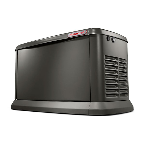
Page 11: Section 2: General Information
General Information Section 2: General Information The Generator 001818 Figure 2-1. 9kW—Components and Control Locations Lock with Cover Oil Fill Cap/Dipstick Oil Drain Hose Fuel Inlet Main Line Circuit Status LED Indicators Composite Base Wi-Fi Module Breaker (Generator Disconnect) Control Panel Airbox with Air Cleaner Sediment Trap Data Decal Location... - Page 12 General Information 001786 Figure 2-2. 11kW–22kW—Components and Control Locations Lock with Cover Exhaust Enclosure Composite Base Wi-Fi Module Main Line Circuit Status LED Indicators Oil Dipstick Data Decal Location Breaker (Generator Disconnect) Airbox with Air Cleaner Oil Drain Sediment Trap Auxiliary Shutdown Switch (all models) Control Panel...
-
Page 13: Data Decals
General Information Data Decals Two decals on the generator provide information about the unit itself and required fuel inlet pressure for proper operation. Model Data Decal Includes important information about the unit including: • model number • serial number • production date •... -
Page 14: Specifications
General Information Specifications Generator Model 9 kW 11 kW 16 kW 20 kW 22 kW Rated Voltage Rated Maximum Load Current (Amps) at Rated 37.5 45.8 66.6 83.3 91.7 Voltage with LP* Main Line Circuit Breaker 40 Amp 50 Amp 70 Amp 90 Amp 100 Amp... -
Page 15: Protection Systems
General Information Protection Systems Emission Information The United States Environmental Protection Agency (US The generator may need to run for long periods of time EPA) (and California Air Resources Board (CARB), for with no operator present to monitor engine or generator engines/equipment certified to California standards) conditions. -
Page 16: Battery Requirements
General Information Battery Requirements Activating the Generator The generator should be activated upon initial start-up. 12 volts, Group 26R-540CCA minimum or Group 35AGM- See the installation manual for complete instructions. 650CCA minimum (not included with unit.) Maintenance for proper battery maintenance procedures. Wi-Fi Module Engine Oil Requirements The generator is equipped with a Wi-Fi module. -
Page 17: Section 3: Operation
Operation Section 3: Operation Site Prep Verification Generator Enclosure Enclosure lid is locked prior to shipment. A set of keys is The generator must be installed to allow unimpeded airflow attached to the cardboard on top of the generator. An into and out of the generator. -
Page 18: Intake Side Panel Removal
Operation Intake Side Panel Removal Figure 3-2. The intake side panel (A) must be 3. Lift intake panel up and away from the generator. removed to access the battery compartment, fuel NOTE: Always lift intake side panel straight up before regulator, and sediment trap. -
Page 19: Auxiliary Shutdown Switch
Operation Auxiliary Shutdown Switch Control Panel Interface All generators are equipped with an external means of Figure 3-7. The control panel interface (A) is located shutting down the generator which complies with the latest under the enclosure lid. Verify both the left and right side NEC code requirement. -
Page 20: Interface Menu Displays
Operation Interface Menu Displays LCD Panel Feature Description Default page displayed if no buttons are pressed for 60 seconds. Normally shows current status message, and current date and time. The highest priority active alarm/warning is automatically posted on this page, as well as flashing the backlight when such a condition is HOME detected. - Page 21 Operation This page intentionally left blank. Owner’s Manual for 60 Hz Air-Cooled Generators...
-
Page 22: Menu System Navigation
Operation Menu System Navigation Press the ESCAPE button from any page to access the MENU, You may need to press the ESCAPE button several ↑ ↓ times before reaching the MENU page. Navigate to the desired menu by using the buttons. - Page 23 Operation 001359 Figure 3-9. Navigation Menu Owner’s Manual for 60 Hz Air-Cooled Generators...
-
Page 24: Setting The Exercise Timer
Operation Setting the Exercise Timer Battery Charger This generator is equipped with a configurable exercise IMPORTANT NOTE: Contact an IASD if the controller timer. Configuration can be performed directly at the control screen displays “CHARGER MISSING AC.” panel or though the Mobile Link™ application. There are two NOTE: The battery charger is integrated into the control settings for the exercise timer: module in all models. -
Page 25: Manual Transfer Operation
Operation Manual Transfer Operation 7. Set MLCB (generator disconnect) (CLOSED). The standby power source now powers the loads. DANGER Electrocution. Do not manually transfer under load. Disconnect transfer switch from all power sources prior to manual transfer. Failure to do so will result in death or serious injury, and equipment damage. -
Page 26: Transfer To Utility Power Source
Operation Automatic Sequence of Transfer to Utility Power Source Operation Shut down generator and transfer to utility source after utility power has been restored. Proceed as follows to manually transfer to utility power and shut down the Utility Failure generator: If the generator is set to AUTO, when utility fails (below 1. -
Page 27: Cold Smart Start
Operation Shutting Generator Down While Cold Smart Start Under Load Or During A Utility The generator will monitor ambient temperature when Outage Cold Smart Start is enabled. The warm-up delay will be adjusted based on prevailing conditions. Cold Smart Start DANGER is enabled at the factory, but can be disabled in the EDIT menu. - Page 28 Operation This page intentionally left blank. Owner’s Manual for 60 Hz Air-Cooled Generators...
-
Page 29: Section 4: Maintenance
Maintenance Section 4: Maintenance Maintenance Performing Scheduled Maintenance Regular maintenance will improve performance and extend engine/equipment life. manufacturer It is important to perform maintenance as specified in the recommends that all maintenance work be performed by Service Schedule for proper generator operation. an Independent Authorized Service Dealer (IASD). -
Page 30: Service Schedule
Maintenance Service Schedule Schedule A Schedule B Daily If Running Continuously Every Service Every Two Years Every Four Years or Before Each Use Year or 200 Hours or 400 Hours ● Inspect enclosure louvers for dirt and debris * ● Inspect lines and connections for fuel or oil leaks ●... -
Page 31: Checking Engine Oil Level
Maintenance Checking Engine Oil Level Engine Oil Requirements To maintain the product warranty, the engine oil should be WARNING serviced in accordance with the recommendations of this manual. For your convenience, Maintenance Kits are Risk of burns. Allow engine to cool before available consisting of engine oil, oil filter, air filter, spark draining oil or coolant. -
Page 32: Changing The Oil And Oil Filter
Maintenance Changing the Oil and Oil Filter 10. Inspect the oil level. Add oil as needed. DO NOT OVERFILL. Proceed as follows to change the oil and oil filter: 11. Insert oil dipstick and/or attach fill cap. 1. Lift the lid and press the MANUAL mode button on 12. -
Page 33: Spark Plug(S)
Maintenance Spark Plug(s) Valve Clearance Adjustment Proceed as follows to inspect spark plug gap(s) and IMPORTANT NOTE: Contact an IASD for service replace spark plug(s) as necessary: assistance. Proper valve clearance is essential for prolonging the life of the engine. 1. -
Page 34: Adjust Valve Clearance
Maintenance 7. When valve clearance is correct, hold pivot ball stud (D) in place with a wrench and tighten rocker arm jam nut. Tighten jam nut according to the following torque specifications: 9 kW 53 in-lb (6.0 Nm) 11 kW 72 in-lb (8.2 Nm) 16–22kW 174 in-lb (19.68 Nm) -
Page 35: Battery Maintenance
Maintenance Battery Maintenance Strictly observe the following precautions when working on batteries: • Remove the 7.5 A fuse from the generator control DANGER panel. Electrocution. Do not wear jewelry while • Disconnect the battery charger as directed in working on this equipment. Doing so will Battery Maintenance. -
Page 36: Cleaning The Sediment Trap
Maintenance 4. Use a clean-out tool (not provided) to remove accumulated moisture and particles from cap and body (B). 5. Wipe the inside of each component with a clean, dry, lint-free cloth. 6. Seal the threads of the cap with appropriate sealing compound. -
Page 37: Perform Leak Test
Maintenance Perform Leak Test Attention After Submersion DO NOT start or operate the generator if it has been DANGER submerged in water. Have an IASD thoroughly clean, dry, Explosion and fire. Fuel and vapors are extremely and inspect the generator following any submersion in flammable and explosive. -
Page 38: Remove From, And Return To Service Procedure
Maintenance Remove From, and Return To 1. Check the tag on the engine for oil viscosity and classification. Drain and fill with proper oil, if Service Procedure necessary. 2. Check the state of the battery. Fill all cells of Remove From Service unsealed batteries to the proper level with distilled water. -
Page 39: Section 5: Troubleshooting / Quick Reference Guide
Troubleshooting / Quick Reference Guide Section 5: Troubleshooting / Quick Reference Guide Generator Troubleshooting Problem Cause Correction Correct short circuit condition by replacing 7.5 A fuse in generator control panel. Contact an Blown fuse. Independent Authorized Service Dealer (IASD) if fuse continues to blow. - Page 40 Troubleshooting / Quick Reference Guide Problem Cause Correction MLCB (generator disconnect) is OFF (OPEN). Reset generator disconnect to ON (CLOSED). Defective transfer switch coi Contact an IASD for assistance Defective transfer relay. Contact an IASD for assistance No transfer to standby after utility Transfer relay circuit open.
-
Page 41: Quick Reference Guide
Troubleshooting / Quick Reference Guide Quick Reference Guide To clear an active alarm, press the OFF mode button on the control panel, then the ENTER button, and finally the AUTO mode button. Contact an IASD if the alarm reoccurs. Active Alarm Problem Things to Check Solution... - Page 42 Troubleshooting / Quick Reference Guide Active Alarm Problem Things to Check Solution Unit will not start in Check the LEDs / OVERVOLTAGE Contact an IASD. AUTO with utility loss. screen for alarms. AUXILIARY Check auxiliary Set auxiliary shutdown switch(es) to Unit will not start.
- Page 44 Waukesha, WI 53187 The Honeywell trademark is used under license from Honeywell International Inc. 1-855-GEN-INFO Honeywell International Inc. makes no representation or warranties with respect to this product. This product is manufactured by Generac Power Systems, Inc., Waukesha, WI 53189, USA. honeywellgenerators.com...