
Related Manuals for Zennio MINiBOX 0-10V X3


Summary of Contents for Zennio MINiBOX 0-10V X3
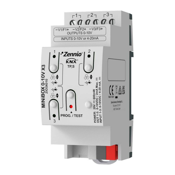
- Page 1 ➢ MINiBOX 0-10V X3/X2/X1 Multifunction Actuator with 3/2/1 fold 0-10V analog input/output ZIO3X010 / ZIO2X010 / ZIO1X010 Application program version: [1.2] User manual edition: [1.2]_a www.zennio.com...
-
Page 2: Table Of Contents
MINiBOX 0-10V X3/X2/X1 CONTENTS Contents ............................2 Document Updates ........................3 Introduction .......................... 4 1.1 MINiBOX 0-10V X3/X2/X1 ....................4 1.2 Installation ........................5 1.3 Start-Up and Power Loss ....................6 Configuration......................... 7 2.1 General ..........................7 2.2 Analog Input ........................9 2.3 Analog Voltage Output .................... -
Page 3: Document Updates
MINiBOX 0-10V X3/X2/X1 DOCUMENT UPDATES Version Changes Page(s) New devices: MINiBOX 0-10V X2 y MINiBOX 0-10V X1 Changes in the software library: • Analog inputs module is added. [1.2]_a • Optimisation of the analog output, heartbeat and fan coil. https://www.zennio.com Technical Support: https://support.zennio.com... -
Page 4: Introduction
1 INTRODUCTION 1.1 MINiBOX 0-10V X3/X2/X1 MINiBOX 0-10V from Zennio is a KNX actuator that aims at fulfilling the climate control needs of KNX environments with integrated fan coil units consisting of two or four pipes, where the valves in the pipes and the fan are controlled through analog 0-10 VDC signals. -
Page 5: Installation
To get detailed information about the technical features of this device, as well as on the installation and security procedures, please refer to the corresponding Datasheet, bundled with the original package of the device and also available at www.zennio.com. https://www.zennio.com Technical Support: https://support.zennio.com... -
Page 6: Start-Up And Power Loss
MINiBOX 0-10V X3/X2/X1 1.3 START-UP AND POWER LOSS Depending on the configuration, some specific actions will be performed during the start- up. For example, the integrator can set whether the output channels should switch to a particular state and whether the device should send certain objects to the bus after the power recovery. -
Page 7: Configuration
The only parameterisable screen that is always available is “General”. From this screen it is possible to activate/deactivate all the required functionality. The following image corresponds to the MINiBOX 0-10V X3. The reduced versions only show the number of channels corresponding to each device. - Page 8 MINiBOX 0-10V X3/X2/X1 Thermostats [disabled/enabled]: enables or disables the “Thermostats” tab on the left menu. See section 2.5 for more details. Logic Functions [disabled/enabled]: enables or disables the “Logic Functions” tab on the left menu. See section 2.6 for more details.
-
Page 9: Analog Input
MINiBOX 0-10V X3/X2/X1 2.2 ANALOG INPUT The MINiBOX 0-10V X3/X2/X1 devices incorporate three/two/one analog inputs which can be used to connect different sensors with different voltage (0-10V, 0-1V y 1-10V) or current (0-20mA y 4-20mA) measurement ranges. Please refer to the specific user manual “Analog Inputs”, available in the MINiBOX 0- 10V product sections, at the Zennio website (www.zennio.com) for detailed information... -
Page 10: Analog Voltage Output
Please refer to the specific user manual “Analog Voltage Output”, available in the MINiBOX 0-10V product sections, at the Zennio website (www.zennio.com) for detailed information about the functionality and the configuration of the related parameters. 2.3.1 OPERATING TIME COUNTER When an analog output is enabled, it is possible to configure the operating time counter, a function that offers the possibility to record the time the output is on or off. - Page 11 MINiBOX 0-10V X3/X2/X1 Seconds [disabled/enabled]: enables or disables the object “[AOx] Operating Time (s)”, corresponding to the counter record (in seconds) of the time that the output remains switched on/off. The maximum value is 235926000 (when the maximum limit is reached, this value is maintained).
-
Page 12: Fan Coil
MINiBOX 0-10V X3/X2/X1 2.4 FAN COIL The MINiBOX 0-10V X3/X2/X1 devices incorporate three/two/one modules to control the fan and valves of a 2 or 4 pipes fan coil unit. Please refer to the specific user manual “Fan Coil ‘Analog’”, available in the MINiBOX 0-10V product sections, at the Zennio website (www.zennio.com) for detailed information... -
Page 13: Thermostats
The MINiBOX 0-10V X3/X2/X1 incorporate three/two/one Zennio thermostats that can be enabled and configured independently. Please refer to the specific “Zennio Thermostat” user manual (available in the MINiBOX 0-10V product sections at the Zennio website, www.zennio.com) for detailed information about the functionality and the configuration of the related parameters. -
Page 14: Logic Functions
Please refer to the specific “Logic Functions” user manual (available in the MINiBOX 0-10V product sections at the Zennio homepage, www.zennio.com) for detailed information about the functionality and the configuration of the related parameters. -
Page 15: Manual Control
MINiBOX 0-10V X3/X2/X1 2.7 MANUAL CONTROL The MINiBOX 0-10V devices, include manual control of its outputs through the respective pushbuttons on the top of the device. Therefore, a specific pushbutton is available per output. Manual operation can be done in two different ways, named as Test On Mode (for testing purposes during the configuration of the device) and Test Off Mode (for a normal use, anytime). - Page 16 MINiBOX 0-10V X3/X2/X1 When the button is pressed, the device will act over the output according to the duration of the button press and to the current output state: ➢ Short press: action equivalent to a 0% or 100% control command in the output control object.
- Page 17 MINiBOX 0-10V X3/X2/X1 ETS PARAMETERISATION The Manual Control (enable by default as explained in section 2.1) is configured from the “Configuration” sub tab itself under “Manual Control”. Figure 6. Manual control. Manual Control [Disabled / Only Test Off Mode / Only Test On Mode /...
-
Page 18: Annex I. Communication Objects
MINiBOX 0-10V X3/X2/X1 ANNEX I. COMMUNICATION OBJECTS “Functional range” shows the values that, regardless of any other values permitted by the bus, given the object size, may be of useful or have a particular meaning because of the specifications or restrictions from the KNX standard or the application program itself. - Page 19 MINiBOX 0-10V X3/X2/X1 2 Bytes C - W - - DPT_Value_2_Ucount 0 - 65535 [AIx] Upper Threshold Value (2-Byte) Unsigned 2 Bytes C - W - - DPT_Value_2_Count -32768 - 32767 [AIx] Upper Threshold Value (2-Byte) Signed 2 Bytes C - W - - 9.xxx...
- Page 20 MINiBOX 0-10V X3/X2/X1 73, 106, 139 1 Bit C - W T U DPT_Heat_Cool [FCx] Mode 0 = Cool; 1 = Heat 74, 107, 140 1 Bit C R - T - DPT_Heat_Cool [FCx] Mode (Status) 0 = Cool; 1 = Heat...
- Page 21 MINiBOX 0-10V X3/X2/X1 91, 124, 157 1 Bit C - W T U DPT_Step [FCx] Manual Fan: Step Control 0 = Down; 1 = Up 92, 125, 158 1 Bit C - W T U DPT_Switch [FCx] Manual Fan: Speed 0 0 = Off;...
- Page 22 MINiBOX 0-10V X3/X2/X1 1 Byte C - W - - DPT_SceneControl 0-63; 128-191 [Thermostat] Scene Input Scene Value 171, 209, 247 2 Bytes C - W T U DPT_Value_Temp -273.00º - 670433.28º [Tx] Temperature Source 1 External Sensor Temperature 172, 210, 248...
- Page 23 MINiBOX 0-10V X3/X2/X1 194, 232, 270 1 Bit C R W - - DPT_Switch [Tx] Main System (Heat) 0 = System 1; 1 = System 2 [Tx] Enable/Disable Secondary 195, 233, 271 1 Bit C - W - - DPT_Enable 0 = Disable;...
- Page 24 MINiBOX 0-10V X3/X2/X1 4 Bytes C R - T - DPT_Value_4_Count -2147483648 - 2147483647 [LF] Function x - Result (4-Byte) Signed 1 Byte C R - T - DPT_Scaling 0% - 100% [LF] Function x - Result (1-Byte) Percentage 2 Bytes...
- Page 25 Join and send us your inquiries about Zennio devices: https://support.zennio.com Zennio Avance y Tecnología S.L. C/ Río Jarama, 132. Nave P-8.11 45007 Toledo (Spain). Tel. +34 925 232 002. www.zennio.com info@zennio.com...