Advertisement
Quick Links
INSTALLATION AND MAINTENANCE INSTRUCTIONS
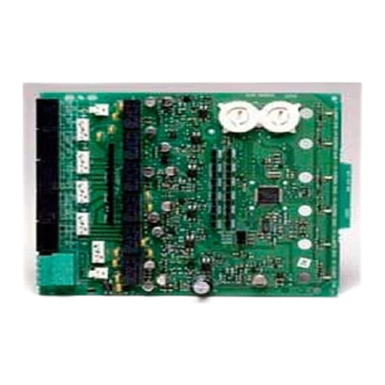
SK-Control-6
Six Circuit Supervised Control Module
SPECIFICATIONS
Normal Operating Voltage:
Stand-By Current:
Alarm Current:
Temperature Range:
Humidity:
Dimensions:
Accessories:
Wire Gauge:
Max. NAC Circuit
Line Loss:
Power Rating Per Circuit:
Max. NAC Current Ratings:
BEFORE INSTALLING
If the modules will be installed in an existing operational system, inform the
operator and local authority that the system will be temporarily out of service.
Disconnect the power to the control panel before installing the modules. This
system contains static sensitive components. Always ground yourself with a
proper wrist strap before handling any circuits so that static charges are re-
moved from the body. The housing cabinet should be metallic and suitably
grounded.
NOTICE: This manual should be left with the owner/user of this equipment.
GENERAL DESCRIPTION
The SK-Control-6 Six Circuit Supervised Control Module is intended for use
in an intelligent alarm system. Each module is intended for switching ap-
plications involving AC, or DC which require wiring supervision. A common
SLC input is used for all modules. Each module has its own address. A pair
of rotary code switches is used to set the address of the first module from 01
to 154. The remaining modules are automatically assigned to the next five
higher addresses. Provisions are included for disabling a maximum of three
unused modules to release the addresses to be used elsewhere. Each module
also has panel controlled green LED indicators. The panel can cause the LEDs
to blink, latch on, or latch off. In order to synchronize strobes, horn/strobes,
and speaker/strobes, a SYNC-1 accessory card (sold separately) must be used
with the SK-Control-6. See the SYNC-1 installation manual for details on how
to install.
Each module has terminals for connection to an external supply circuit for
powering devices on its NAC. Each supply must be power limited and its volt-
age/current limits must be at or below those specified. There is a short circuit
protection monitor for each module. This is provided to protect the external
power supply against short circuit conditions on the NAC.
SK-460-006
15-32 VDC
2.25 mA
35 mA (assumes all six relays have been switched and all six LEDs solid on)
32°F to 120°F (0°C to 49°C)–10°C to 55°C
10 to 85% Non-condensing
6.8˝ H x 5.8˝ W x 1.25˝ D
IDP-ACB Cabinet and chassis
12-18 AWG
4 VDC
63 W @ 70.7 VAC; 50 W @ 25 VAC
For class B wiring systems, 3A
For class A wiring systems, 2A
firealarmresources.com
ShIPPED ON BOARD:
(1) Small shunt in A/B select position (Shipped in Class B position, remove
shunt for Class A)
(6) Large shunts on Enable Power Supply Monitors
(6) Large shunts on Disable Short Circuit Protection
(3) Large shunts on Sync Generator
INCLUDED:
(7) 1 x 4 Terminal Blocks
(2) 1
(4) Machine Screws
(5) Short Power
Suppy Jumpers
(2) Nuts
(1) Long Power Supply Jumper
1
12 Clintonville Road, Northford, CT 06472
203.484.7161; Fax: 203.484.7118
www.silentknight.com
1
/
˝ (32mm)
(15) Large Shunts
4
Stand offs
(2) Small Shunts
(6) 47k Ohm End
of Line Resistors
(2) EOL Relay Connector
Assmeblies
I56-3437-002
Advertisement

Related Manuals for Honeywell SILENT KNIGHT SK-Control-6


Summary of Contents for Honeywell SILENT KNIGHT SK-Control-6
- Page 1 INSTALLATION AND MAINTENANCE INSTRUCTIONS SK-Control-6 12 Clintonville Road, Northford, CT 06472 203.484.7161; Fax: 203.484.7118 Six Circuit Supervised Control Module www.silentknight.com SPECIFICATIONS Normal Operating Voltage: 15-32 VDC Stand-By Current: 2.25 mA Alarm Current: 35 mA (assumes all six relays have been switched and all six LEDs solid on) Temperature Range: 32°F to 120°F (0°C to 49°C)–10°C to 55°C Humidity:...
-
Page 2: Compatibility Requirements
TABLE 1: ShORT CIRCUIT PROTECTION - UL 864 9Th EDITION REqUIREMENTS NOTICE TO USERS, INSTALLERS, AUTHORITIES HAVING JURISDICTION, AND OTHER INVOLVED PARTIES This product incorporates field-programmable software. In order for the product to comply with requirements in the Standard for Control Units and Accessories for Fire Alarm Systems, UL 864, certain programming features or options must be limited to specific values or not used at all as indicated below. - Page 3 Step 1: Insert the bottom edge of the SK-Control-6 module down into a rear enable short circuit protection for an address, remove the corresponding slot of the chassis. shunts on the “Disable Short Protection” area. When enabled, this option will isolate a short occurring on any active circuit allowing the remaining Step 2: Carefully swing the upper edge of the board towards the back of the circuits to continue normal operation.
-
Page 4: Jumper Location
POwER SUPPLY wIRING AND SUPERVISION TABLE 4 Table 3 gives an overview of how the power connectors, T0–T5 and T10–T15, JUMPER LOCATION NAC PAIR SHARING SUPPLY are interconnected by the circuit board (PCB). The external supply connection T11* +0 and +1 points, at T0–T5, are marked by PS–... - Page 5 FIGURE 7: ExAMPLE OF CLASS B, STYLE Y NAC CONFIGURATION wITh A SINGLE SUPPLY ShARED BY 2 NACS. EXTERNAL POWER (–) (–) – SUPPLY BASE ADDRESS – 6 7 8 9 (–) (–) – – – EOLR-1 A/B SELECT DISABLE 1 DISABLE 2 DISABLE 3 POWER-LIMITED...
- Page 6 – Increase the separation between the equipment and receiver. – Connect the equipment into an outlet on a circuit different from that to which the receiver is connected. – Consult the dealer or an experienced radio/TV technician for help. SK-460-006 I56-3437-002 ©2009 Honeywell International Inc. firealarmresources.com...