Advertisement
Quick Links
Advertisement

Related Manuals for HIKVISION DS-2781 Series


Summary of Contents for HIKVISION DS-2781 Series
- Page 1 Explosion-Proof Terminal Box Installation Guide UD08260B-A 01000120180920...
- Page 2 Any and all information, including, among others, wordings, pictures, graphs are the properties of Hangzhou Hikvision Digital Technology Co., Ltd. or its subsidiaries (hereinafter referred to be “Hikvision”). This user manual (hereinafter referred to be “the Manual”) cannot be reproduced, changed, translated, or distributed, partially or wholly, by any means, without the prior written permission of Hikvision.
- Page 3 LOSS OF BUSINESS PROFITS, BUSINESS INTERRUPTION, OR LOSS OF DATA OR DOCUMENTATION, IN CONNECTION WITH THE USE OF THIS PRODUCT, EVEN IF HIKVISION HAS BEEN ADVISED OF THE POSSIBILITY OF SUCH DAMAGES. REGARDING TO THE PRODUCT WITH INTERNET ACCESS, THE USE OF PRODUCT SHALL BE WHOLLY AT YOUR OWN RISKS.
- Page 4 Terminal Box·Installation Guide IN THE EVENT OF ANY CONFLICTS BETWEEN THIS MANUAL AND THE APPLICABLE LAW, THE LATER PREVAILS. Regulatory Information Intended Use of the Terminal Box and the Supplied Cable Gland with Elastomeric Sealing Rings ATEX: II 2 G D Ex db IIC T6 Gb/Ex tb IIIC T80℃ Db IP68 IECEx: Ex db IIC T6 Gb/Ex tb IIIC T80℃...
- Page 5 Terminal Box·Installation Guide Explosion-Proof Terminal Box WARNING: DO NOT OPEN WHEN EXPLOSIVE ATMOSPHERE IS PRESENT AFTER DE-ENERGIZING, DELAY 5 MINUTES BEFORE OPENING The terminal box can be used in hazardous areas Zone 1, Zone 2, Zone 21, and Zone 22 where ignitable concentrations of flammable gases, vapors or liquids (with T1 to T6 classification) or combustible dust or ignitable fibers/flyings ARE LIKELY TO...
- Page 6 Terminal Box·Installation Guide selection and erection, beside of the manufacturer’s operation instruction or its National equivalent. 3. Repair and overhaul shall comply with IEC 60079-19: latest version or its National equivalent. Safety Instruction These instructions are intended to ensure that user can use the product correctly to avoid danger or property loss.
- Page 7 Terminal Box·Installation Guide Ground wire cross-sectional area of not less than the phase connector cross-sectional area level, at least 4 mm ● All the electrical operation should be strictly compliance with the electrical safety regulations, fire prevention regulations and other related regulations of the nation and region. ●...
- Page 8 Terminal Box·Installation Guide ● Regular part replacement: a few parts of the equipment shall be replaced regularly according to their average enduring time. The average time varies because of differences between operating environment and using history, so regular checking is recommended for all the users.
-
Page 9: Table Of Contents
Terminal Box·Installation Guide Table of Contents 1 Introduction ..................9 1.1 Overview ................. 9 1.2 Model Description............9 2 Appearance ................... 11 3 Installation ..................13 3.1 DS-2781 and DS-2783 Series Installation ....... 13 3.2 DS-2780 and DS-2782 Series Installation ....... 19... -
Page 10: Introduction
Terminal Box·Installation Guide 1 Introduction Overview Explosion-proof terminal box is specially designed for camera wiring in explosive environment. Explosion-proof terminal box adopts stainless steel enclosures, receiving an IP68 rating for ingress protection. Application Scenarios: oil industry, chemical industry, port, grain processing industry, etc. - Page 11 With /316L: stainless steel 316L Without /316L: stainless steel 304 Feature: explosion-proof Product type: accessory Product series Power adapter included: 1 and 3 NO power adapter: 0 and 2 Product type: terminal box Material: stainless steel Front-end product Hikvision product Model Explanation...
-
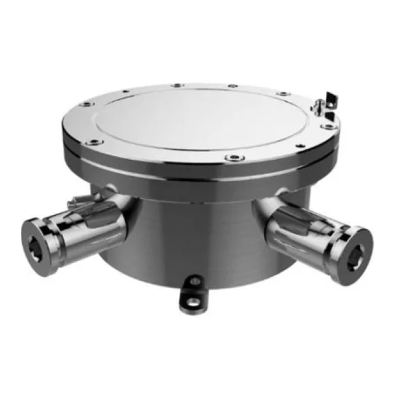
Page 12: Appearance
Terminal Box·Installation Guide 2 Appearance 96.8 Ø 182 4-Ø 8.5 Explosion-Proof Terminal Box Overview Figure 2-1... - Page 13 Terminal Box·Installation Guide Elastomeric Sealing Rings Overview Figure 2-2 Accessory Description Table 2-1 Description Elastomeric sealing rings (DS-2780 and DS-2782 series included) M25×1.5 to G3/4 adapter (DS-2780 and DS-2782 series included)
-
Page 14: Installation
Terminal Box·Installation Guide 3 Installation Before you start: ● Make sure the device in the package is in good condition and all the assembly parts are included. ● Make sure all the related equipment is power-off during the installation. ● Check the specification of the products for the installation environment. - Page 15 Terminal Box·Installation Guide Steps: Drill four screw holes (Ø8 mm) according to the dimension of the terminal box (see Figure 2-1), and insert four M8 × 80 expansion bolts. Secure the terminal box on mounting place. Spring Washer Flat Washer Secure Terminal box Figure 3-1 Disassemble the terminal box.
- Page 16 Terminal Box·Installation Guide Plug Gasket Sealing Ring Cover Safety Rope Disassemble Terminal Box (1) Figure 3-2 Loosen the plugs at “Camera” end and its opposite end, and take out the gaskets and the sealing rings. Note: Normally, two ends are enough for cable routing. The others are reserved for unexpected conditions.
- Page 17 Terminal Box·Installation Guide Disassemble Terminal Box (2) Figure 3-3 Route cables and wiring. Install the camera cable to cable gland (sealed with setting compound). Refer to installation guide of the cable gland for detailed steps. Secure the cable gland together with the cable gland sealing ring (a component of cable gland) to the “Camera”...
- Page 18 Terminal Box·Installation Guide Cable Gland Cable Gland Sealing Ring Install Camera Cable Figure 3-4 Connect wires to corresponding terminals. Install a RJ45 head to network cables and plug it to RJ45①. Repeat above steps to route source cables through the opposite “Camera”...
- Page 19 Terminal Box·Installation Guide To Camera RJ45① RJ45② To Source Wiring Figure 3-5 Screw the cover back to terminal box.
-
Page 20: Ds-2780 And Ds-2782 Series Installation
Terminal Box·Installation Guide Check to ensure the O-shape ring stays in terminal box. Align the locating hole of the cover with the locating pin on box, and gently lower the cover back to the box. Note: When lowering the cover, prevent the explosion suppression surfaces from bump or scratch. - Page 21 Terminal Box·Installation Guide Secure Terminal box Figure 3-7 Disassemble the terminal box. Plug Gasket Sealing Ring Cover Safety Rope Disassemble Terminal Box (1) Figure 3-8...
- Page 22 Terminal Box·Installation Guide Loosen the gland nuts at the “Camera” end and the opposite “Camera” end, and take out the gaskets and the sealing rings. Note: Normally, two ends are enough for cable routing. The others are reserved for unexpected conditions. Keep the unused ends firmed sealed (torque 50 Nm).
- Page 23 Terminal Box·Installation Guide Thread the camera cable through supplied adapter, gasket, and supplied sealing ring. Note: Select a suitable sealing ring according to the diameter of your cable. Four kinds of sealing rings are supplied (Ø12mm, Ø9mm, Ø7mm, and Ø5mm). Secure the gland nut to the “Camera”...
- Page 24 Terminal Box·Installation Guide Remove Cap on Supplied Adapter Figure 3-11 Thread the camera cable through sealing ring (together with flexible conduit) and the adapter, and secure the adapter to the conduit. Install Adapter to Conduit Figure 3-12 Thread the camera cable through the adapter, gasket, supplied sealing ring, and the box outlet.
- Page 25 Terminal Box·Installation Guide Adapter Torque 50 Nm Gasket Sealing Ring Secure the Adapter to Terminal Box Figure 3-13 Connect wires to corresponding terminals. Note This terminal box transmits power without making any change to...
- Page 26 Terminal Box·Installation Guide To Camera RJ45① RJ45② To Source Wiring Figure 3-14 Install a RJ45 head to network cables and plug it to RJ45①.
- Page 27 Terminal Box·Installation Guide Repeat above steps to route source cables through the opposite “Camera” end, connect wires, install a RJ45 head and plug it to RJ45②. Screw the cover back to terminal box. Check to ensure the O-shape ring stays in terminal box. Align the locating hole of the cover with the locating pin on box, and gently lower the cover back to the box.