Table of Contents
Advertisement
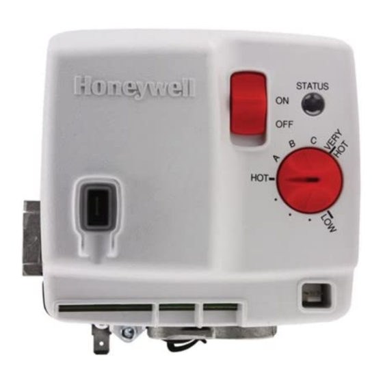
WV4262B Powered Damper
Water Heater Controls
APPLICATION
The WV4262B Water Heater Control System is
designed for power damper water heater applications.
The WV4262B provides these features:
• Gas regulation and manual valve features
• Intermittent spark-to-pilot ignition
• Flame supervision using flame rectification
sensing through the spark rod. This flame sense
circuit uses patented technology to create a
robust sensing signal that is independent of AC
line polarity and appliance earth grounding.
• Water temperature sensing using solid state
sensors potted in a submersion well assembly
• Manually resettable High Temperature Cutout
(TCO)
• Damper motor control with position sensing
• Variable resistance flammable vapor sensor with
a sensing and control algorithm to provide
automatic shutdown when hydrocarbon vapors
such as gasoline are detected
• Retains up to 10 fault code histories in non-
volatile memory (available through the
EnviraCOM™ communication port)
• Solid state setpoint adjustment over a factory
preset temperature range using a linear
potentiometer to provide high resolution
adjustment
Special control features are available to address
items such as stacking. See a Honeywell Product
Specialist for more information.
The specific application of the WV4262B System is
the responsibility of the appliance manufacturer. See
the Specifications below for temperature ranges and
regulator types. The WV4262B system refers to the
combination of the valve and the electronic control
module.
INSTALLATION INSTRUCTIONS
SPECIFICATIONS
IMPORTANT
WV4262B Controls provide direct replace-
ment only; do not substitute other models.
Body Pattern: 90 degree with 1/2 in. inlet and 1/2 in.
inverted flare outlet.
Natural gas model has right-hand threaded
inverted outlet.
LP gas model has left-hand threaded inverted out-
let.
Mounting: Mounting in upright position only.
Electrical Tolerences:
Voltage Minimum: 18 VAC RMS, 60 Hz.
Voltage Maximum: 30 VAC RMS, 60 Hz.
Current in Running Mode: 0.3 Amps @ 24 VAC (plus
inducer motor draw)
Current in Idle Mode: 0.3 Amps Max @ 24 VAC
Damper Relay: 24 VAC RMS, 1 Amp Switching Cur-
rent. 75,000 Cycles Life @ max load.
Capacity: See Table 1.
Conversion: Use conversion factors in Table 2 to
convert capacities for other gases.
Regulation Range (Btuh);
With 1/2 in. NPT inlet and 1/2 in. Inverted Flare Out-
let:
Natural Gas:
Minimum: 30,000
Maximum: 100,000
LP Gas:
Minimum: 40,000.
Maximum: 100,000
Inlet Pressure Range:
See appliance rating plate for Inlet Pressure range
recommendation
1/2 PSI (14.0" w. c.) maximum inlet pressure allowed
for proper operation.
Operational Environment:
Operating Ambient Temperature Range:
32 °F to 150 °F (0 °C to 65 °C)*
Shipping and Storage Temperature Range
-20 °F to 120 °F (-29 °C to 49 °C)
* Gas valve regulation range is guaranteed from 32 °F
to 150 °F (0 °C to 66 °C)
69-2496-03
Advertisement
Table of Contents

Related Manuals for Honeywell WV4262B


Summary of Contents for Honeywell WV4262B
- Page 1 See a Honeywell Product Maximum: 100,000 Specialist for more information. Inlet Pressure Range: The specific application of the WV4262B System is See appliance rating plate for Inlet Pressure range the responsibility of the appliance manufacturer. See recommendation the Specifications below for temperature ranges and 1/2 PSI (14.0"...
- Page 2 0.64 specific gravity natural gas at 0.37 kPa pressure drop). Valves are guaranteed at only 77 percent of the rating. CAPACITY PRESSURE DROP M32315 Fig. 1. Typical capacity curve for WV4262B Family Water Heater Control System. Table 2. Gas Capacity. Gas Type Flow (kBTU/hr) Pressure Drop (in. w.c.) 1.43...
-
Page 3: Planning The Installation
Proper 5-5/16 (135) insulation or shielding should be provided by the appliance manufacturer. Verify proper air circulation is maintained when the appliance is installed. 7-13/64 (183) M32296 Fig. 2. WV4262B dimensions in inches (mm). 69-2496—03... -
Page 4: Installation
WV4262B POWERED DAMPER WATER HEATER CONTROLS INSTALLATION Location The WV4262B is mounted on the outside of the water heater tank. See Fig. 3. When Installing this Product… 1. Read these instructions carefully. Failure to Install Control to Water Tank follow them could damage the product or cause a hazardous condition. -
Page 5: Connect Gas Supply
WV4262B POWERED DAMPER WATER HEATER CONTROLS Connect Gas Supply DROP PIPED HORIZONTAL WARNING SUPPLY Fire or Explosion Hazard. Can cause severe injury, death, or property damage. Check for gas leaks with soap and water solution any time work is done on a gas system. -
Page 6: Turn On Main Burner
WV4262B POWERED DAMPER WATER HEATER CONTROLS 5. Connect the Pilot Assembly lead to the Spark ON/OFF connector. SWITCH HONEYWELL WV4262B APPLY WRENCH HERE WHEN SPARK CONNECTOR CONNECTING (TO PILOT ASSEMBLY Q3451A) SUPPLY LINE 24 VAC COMMON 3 2 1 24 VAC... - Page 7 WV4262B POWERED DAMPER WATER HEATER CONTROLS Gas Leak Test a. Meter Clocking: Convert flow rate to Btuh as described in form 70-2602, Gas Controls 1. Paint pipe connections upstream of the water Handbook, and compare to Btuh input rating heater control with rich soap and water solution.
-
Page 8: Maintenance
WV4262B POWERED DAMPER WATER HEATER CONTROLS MAINTENANCE SERVICE WARNING WARNING Fire or Explosion Hazard Fire or Explosion Hazard Can cause severe injury, death, or property Can cause severe injury, death, or property damage. damage. Do not attempt to take the control apart or Do not disassemble the water heater control;... -
Page 9: Troubleshooting
WV4262B POWERED DAMPER WATER HEATER CONTROLS Sequence Mode Description Energize main gas valve The main valve is energized (when flame is proved above the “RUN” level). Wait 3 seconds to stabilize flame Flame and Pressure Switch signals are ignored for 3 seconds after the main valve is energized (Flame Stabilization Period). - Page 10 WV4262B POWERED DAMPER WATER HEATER CONTROLS Green LED Status Indicates Check/Repair Six-One Soft Lockout - Failed Trial For • Check gas supply. Flash, three Ignition • Verify air is purged from gas lines if appliance has not run for second pause an extended period of time.
- Page 11 WV4262B POWERED DAMPER WATER HEATER CONTROLS CHECK: SLIDE SWITCH TO THE ON POSITION, TANK TEMPERATURE IS AT OR CLOSE TO HOT SET POINT TURN THE SET KNOB TO HOT; WIRING OF LINE VOLTAGE SUPPLY DAMPER SHOULD OPEN TEMPERATURE SENSOR AND FLAMMABLE VAPOR...
-
Page 12: Instructions To The Homeowner
WV4262B POWERED DAMPER WATER HEATER CONTROLS INSTRUCTIONS TO THE STOP: READ THE HOMEOWNER WARNINGS. TURNING ON THE WARNING Fire or Explosion Hazard. APPLIANCE Can cause severe injury, death, or property damage. If the appliance does not turn on when the setpoint...