Table of Contents
Advertisement
SHARP SERVICE MANUAL
PARTS IDENTIFICATION AND SPECIFIC INFORMATION ......................................................
EXTERNAL DIMENSION .........................................................................................................
CAUTIONS FOR USE ..............................................................................................................
HOW TO USE ...........................................................................................................................
WIRING DIAGRAM ...................................................................................................................
INSTALLATION ADVICE ..........................................................................................................
SHOWER SET ...........................................................................................................................
REPLACING METHOD FOR MAIN PARTS ..............................................................................
TROUBLESHOOTING ..............................................................................................................
CIRCUIT DIAGRAM (PCB CONTROL ASS'Y) .........................................................................
SERVICE PARTS LIST ...............................................................................................................
ELECTRIC WATER HEATER
In the interests of user-safety (Required by safety
regulations in some countries) the set should be restore
to its original condition and only parts identical to those
specified should be used.
TABLE OF CONTENTS
SHARP CORPORATION
MODELS
WH-A55
WH-A57
WH-A58P
WH-HOT HOT
Page
2
3
3
4
5
5-9
9
10-14
15
16
17-21
Advertisement
Table of Contents

Related Manuals for Sharp WH-A55


Summary of Contents for Sharp WH-A55
-
Page 1: Table Of Contents
SHARP SERVICE MANUAL ELECTRIC WATER HEATER MODELS WH-A55 WH-A57 WH-A58P WH-HOT HOT In the interests of user-safety (Required by safety regulations in some countries) the set should be restore to its original condition and only parts identical to those specified should be used. -
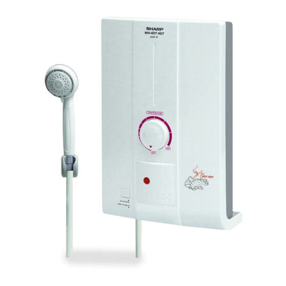
Page 2: Parts Identification And Specific Information
Heater lamp ELB checker button Breaker angle support Water volume knob (WH-A57, WH-A58P only) Main water valve Shower hose SPECIFIC INFORMATION Model WH-A55 WH-A57 WH-A58P WH-HOT HOT Rated voltage (V) Rated frequency (Hz) Power consumption (W) 3,500 4,500 Water supply system... -
Page 3: External Dimension
(to avoid water automatically flowing when you are not in the bathroom after tap water flow resumes). 10. While we using a product if that is stop working immediately as we do not know the cause, please inform the SHARP service center for proceed to repair. -
Page 4: How To Use
HOW TO USE BEFORE USE The installation work is to be done by the Authorized “SHARP” Dealer. The electric home shower unit must earthed. Special skill is required. Never try to repair the unit by yourself. 1. Open the main water valve from the home main water pipe. -
Page 5: Wiring Diagram
WIRING DIAGRAM INSTALLATION ADVICE 1. Before installation. 1.1 Please check water pressure before operating this unit. Minimum water pressure : 0.02 MPa (0.21 Bar). Maximum water pressure : 0.34 MPa (3.39 Bar). Please follow the picture below to check water pressure. Water shall overflow at the end of the tube within 2.3 meters above the faucet. - Page 6 2.2 Removing the unit cover. Turn the temperature knob to “OFF” position and remove the screw underneath the unit. Open the cover by lifting from the bottom. Screw Fig. 8 2.3 Mounting the unit to the wall. Drill two 6 millimeters holes in the wall with approximately 25 millimeters in depth. Install wall anchors into the holes.
- Page 7 2.5 The shower assembly. The joint and shower hose counterclockwise with the shower head. Notification in connecting the shower hose. Connect to the shower head. Shower head Joint Connect to the unit. Shower hose Fig. 12 2.6 Installation the shower stand. Ensure that the shower stand located in the level that the top part of the shower head is not higher than the top part of the unit when hanging the shower head.
- Page 8 4. Electric wire connections. 4.1 Before connection the wires, please make sure the main breaker is off to cut off power. Use dual insulated wire with at least 4 square millimeters cross-section. Connect electric wire to the unit from the main breaker board through the main breaker which is located the bathroom.
-
Page 9: Shower Set
4.3 The ground wire must be connected to grounding point on the unit. Grounding process. Ground rod installation, select the area where moisture stored in the soil and away from flood area with no sand or limestone. The diameter of ground rod is not less than 16 millimeters and the length is not less than 240 centimeters. -
Page 10: Replacing Method For Main Parts
REPLACING METHOD FOR MAIN PARTS REMOVE OF SHOWER HOSE 1. Turn out the joint body between the body with the shower hose manually. Never use other tools to avoid breaking plastic parts. Body Shower hose Fig. 20 REMOVE OF BODY 1. - Page 11 REMOVE OF TRIAC 1. Remove the body in accordance with “REMOVE OF BODY”. 2. Disconnect 3 lead wires from the triac. 3. Remove 2 screws holding the triac to the heater tank ass’y. 4. Now the triac is free. Brown lead wire Triac lead wire White lead wire Breaker lead wire...
- Page 12 REMOVE OF BODY VALVE ASS’Y AND WATER OUTLET 1. Remove the body in accordance with “REMOVE OF BODY”. 2. Remove the reed SW. in accordance with “REMOVE OF REED SWITCH”. 3. Detach 2 clamping springs holding the body valve ass’y and the water outlet to the heater tank ass’y. 4.
- Page 13 REMOVE OF PCB CONTROL ASS’Y 1. Remove the body in accordance with “REMOVE OF BODY”. 2. Disconnect reed SW. lead wire from PCB control ass’y. Volume SW. lead wire 3. Remove the screw holding the PCB control ass’y. Screw 4. Cut off the volume SW. lead wire at the PCB control ass’y. PCB control ass’y 5.
- Page 14 Note : For disassembly Cut off the lead wire from PCB control ass’y. Volume SW. White lead wire Orange lead wire Orange lead wire Blue lead wire Fig. 28 REMOVE OF BREAKER 1. Remove the body in accordance with “REMOVE OF BODY”. 2.
-
Page 15: Troubleshooting
REMOVE OF NEON LAMP ASS’Y 1. Remove the body in accordance with “REMOVE OF BODY”. 2. Remove the screw holding the neon lamp ass’y to the back cover. 3. Cut neon lamp lead wire to PCB control ass’y. 4. Now the neon lamp ass’y is free. Screw Black lead wire Neon lamp ass’y... -
Page 16: Circuit Diagram (Pcb Control Ass'y)
CIRCUIT DIAGRAM (PCB CONTROL ASS’Y) -
Page 17: Service Parts List
SERVICE PARTS LIST Model WH-A55 PARTS CODE REF. NO DESCRIPTION Q’TY PRICE (FEC) PRINTING & PACKAGING MATERIAL 71T107 INSTRUCTION BOOK 71T100 SET PACKING CASE 71T101 CARTON BOX 71T102 NAME PLATE 71B1051 LOWER PAD 71B1061 UPPER PAD MECHANICAL PARTS 71T200ASY BODY ASS’Y 7N7122 TEMP. - Page 18 Model WH-A57 PARTS CODE REF. NO DESCRIPTION Q’TY PRICE (FEC) PRINTING & PACKAGING MATERIAL 71T107 INSTRUCTION BOOK 71U100 SET PACKING CASE 71U101 CARTON BOX 71U102 NAME PLATE 71B1051 LOWER PAD 71B1061 UPPER PAD MECHANICAL PARTS 71U200ASY BODY ASS’Y 7N7122 TEMP. CONTROL KNOB 7N706 SPLIT PIN 7N6182...
- Page 19 Model WH-A58P PARTS CODE REF. NO DESCRIPTION Q’TY PRICE (FEC) PRINTING & PACKAGING MATERIAL 71T107 INSTRUCTION BOOK 71U120 SET PACKING CASE 71U121 CARTON BOX 71U122 NAME PLATE 71B1051 LOWER PAD 71B1061 UPPER PAD MECHANICAL PARTS 71U230ASY BODY ASS’Y 7N7123 TEMP. CONTROL KNOB 7N706 SPLIT PIN 7N6182...
- Page 20 Model WH- HOT HOT PARTS CODE REF. NO DESCRIPTION Q’TY PRICE (FEC) PRINTING & PACKAGING MATERIAL 71X107 INSTRUCTION BOOK 71X100 SET PACKING CASE 71X101 CARTON BOX 71X102 NAME PLATE 71B1051 LOWER PAD 71B1061 UPPER PAD MECHANICAL PARTS 71X200ASY BODY ASS’Y 7N7122 TEMP.