Advertisement
SHARP SERVICE MANUAL
PARTS IDENTIFICATION AND SPECIFIC INFORMATION ..............................................
EXTERNAL DIMENSION ...................................................................................................
CAUTION FOR USE ..........................................................................................................
HOW TO USE ....................................................................................................................
WIRING DIAGRAM ............................................................................................................
INSTALLATION ADVICE ....................................................................................................
POWER SUPPLY INSTALLATION .....................................................................................
SHOWER SET ...................................................................................................................
REPLACING METHOD FOR MAIN PARTS ......................................................................
TROUBLESHOOTING .......................................................................................................
CIRCUIT DIAGRAM (PCB-1) .............................................................................................
SERVICE PARTS LIST ......................................................................................................
ELECTRIC WATER HEATER
In the interests of user-safety (Required by safety
regulations in some countries) the set should be restore
to its original condition and only parts identical to those
specifi ed should be used.
TABLE OF CONTENTS
SHARP CORPORATION
MODELS
WH-236E
WH-239EP
WH-246E
Page
2
3
3
4
5
5-8
8-10
10
11-15
16
17
18-24
Advertisement
Table of Contents

Related Manuals for Sharp WH-236E


Summary of Contents for Sharp WH-236E
-
Page 1: Table Of Contents
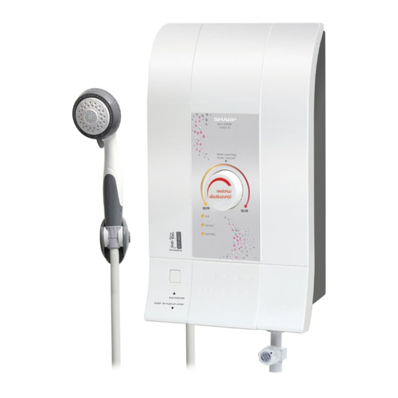
SHARP SERVICE MANUAL ELECTRIC WATER HEATER MODELS WH-236E WH-239EP WH-246E In the interests of user-safety (Required by safety regulations in some countries) the set should be restore to its original condition and only parts identical to those specifi ed should be used. - Page 2 ELB lamp Power lamp ELB button Heater lamp Power SW. button Water volume knob Shower hose Main water valve Breaker angle support SPECIFIC INFORMATION WH-236E WH-239EP WH-246E Model Rated voltage Rated frequency Power consumptions 3,500 4,500 Single point Water supply system...
-
Page 3: External Dimension
However, if ELB light (green) still off, turn off this appliance by press the Power SW. button then contact your SHARP service facility or SHARP dealer. 9. Close supervision is necessary in order to check on the water temperature when used by children, elderly, patients and disabled person. -
Page 4: How To Use
HOW TO USE BEFORE USE The installation work is to be done by the Authorized “SHARP” Dealer. The electric home shower unit must earthed. Special skill is required. Never try to repair the unit by yourself. 1. Open the main water valve from the home main water pipe. -
Page 5: Wiring Diagram
WIRING DIAGRAM INSTALLATION ADVICE 1. BEFORE INSTALLATION Please check water pressure before operating this unit. Minimum water pressure : 0.02 MPa (0.21 Bar). Maximum water pressure : 0.34 MPa (3.39 Bar). Please follow the picture below to check water pressure. Water shall overfl ow at the end of the tube within 2.3 meters above the faucet. - Page 6 2.2. Removing the unit cover. Remove the screw underneath the unit. Open the cover by lifting from the bottom. Screw Fig. 8 2.3. Mounting the unit to the wall. Drill two 6 millimeters holes in the wall with approximately 25 millimeters in depth. Install wall anchors into the holes.
- Page 7 2.5. The shower assembly. The joint the shower hose counterclockwise with the shower. Notifi cation in connecting the shower hose. Connect to the shower head. Shower head Connect to the unit. Joint Shower hose Fig. 12 2.6. Installation the shower stand. Ensure that the shower stand located in the level that the top part of the shower head is not higher than the top part of the unit when hanging the shower head.
- Page 8 1. Be sure to cut off the main power supply switch every time before starting any electrical work Use dual insulated wire with at least 4 square meters cross-section (WH-236E, WH-239EP). Use dual insulated wire with at least 6 square meters cross-section (WH-246E).
-
Page 9: Shower Set
3. The ground wire must be connected to grounding point on the unit. Grounding process. Ground rod installation, select the area where moisture stored in the soil and away from fl ood area with no sand or limestone. The diameter of ground rod is not less than 16 millimeters and the length is not less than 240 centimeters. -
Page 10: Replacing Method For Main Parts
REPLACING METHOD FOR MAIN PARTS REMOVE OF SHOWER HOSE 1. Turn out the joint body between the body with the shower hose manually. Never use other tools to avoid breaking plastic parts. Body Shower hose Fig. 20 REMOVE OF BODY 1. - Page 11 REMOVE OF POWER SWITCH BUTTON 1. Remove the body in accordance with “REMOVE OF BODY”. 2. Push the claws of the guide pin by fl at screwdriver and remove the guide pin from the body. 3. Now the power SW. button is free. Body Guide pin Remove the guide pin...
- Page 12 REMOVE OF TRIAC 1. Remove the body in accordance with “REMOVE OF BODY”. 2. Disconnect 3 lead wires from the triac. 3. Remove 2 screws holding to the heater tank ass’y. 4. Now the triac is free. White lead wire Breaker lead wire Brown lead wire Triac lead wire...
- Page 13 REMOVE OF PCB-A 1. Remove the body in accordance with “REMOVE OF BODY”. 2. Pull out all the lead wires from the PCB-A. 3. Remove 3 screws holding the PCB-A. 4. Now the PCB-A is free. Screw PCB-A Back cover Fig.
- Page 14 REMOVE OF BODY VALVE ASS’Y AND WATER OUTLET 1. Remove the body in accordance with “REMOVE OF BODY”. 2. Remove the reed SW. in accordance with “REMOVE OF REED SWITCH”. 3. Remove the push SW. set in accordance with “REMOVE OF PUSH SWITCH SET”. 4.
- Page 15 REMOVE OF BREAKER 1. Remove the body in accordance with “REMOVE OF BODY”. 2. Remove split pin holding the breaker angle support to the breaker. 3. Remove 2 screws holding 2 breaker lead wires to the breaker. 4. Remove 2 screws holding the breaker to the back cover. 5.
-
Page 16: Troubleshooting
TROUBLESHOOTING Problem Possible cause Corrective action Water is not hot. Power switch button is defected. Check or replace mechanical parts in - ELB lamp is not lights up. Power switch button. - Power lamp is not lights up. Check electrical leakage point from ELB breaker is cut off or defected. -
Page 17: Circuit Diagram (Pcb-1)
CIRCUIT DIAGRAM (PCB-A) -
Page 18: Service Parts List
SERVICE PARTS LIST Model WH-26E PARTS CODE REF. NO DESCRIPTION Q’TY PRICE (FEC) PRINTING & PACKAGING MATERIAL 71M107 INSTRUCTION BOOK 71M100 SET PACKING CASE 71M101 CARTON BOX 71M102 NAME PLATE 71M104 WIRING DIAGRAM STICKER 71J105 LOWER PAD 71J106 UPPER PAD MECHANICAL PARTS 71M200SET BODY SET... - Page 19 PARTS CODE REF. NO DESCRIPTION Q’TY PRICE (FEC) ELECTRIC PARTS 7A605 BREAKER 220V, 30A 71M402 PCB - A 71M409 LEAD WIRE FOR PCB - A CN2 71M403 PCB - B 71M411 BREAKER LEAD WIRE BLACK 7D2101 MICRO SWITCH 7R405 REED SWITCH ASS’Y 71M408 LEAD WIRE FOR PCB - A CN1 71J407...
- Page 20 Model WH-239EP PARTS CODE REF. NO DESCRIPTION Q’TY PRICE (FEC) PRINTING & PACKAGING MATERIAL 71M107 INSTRUCTION BOOK 71M120 SET PACKING CASE 71M121 CARTON BOX 71M122 NAME PLATE 71M104 WIRING DIAGRAM STICKER 71J105 LOWER PAD 71J106 UPPER PAD MECHANICAL PARTS 71M230SET BODY SET 71M231 TEMP.
- Page 21 PARTS CODE REF. NO DESCRIPTION Q’TY PRICE (FEC) ELECTRIC PARTS 7A605 BREAKER 220V, 30A 71M402 PCB - A 71M409 LEAD WIRE FOR PCB - A CN2 71M403 PCB - B 71M411 BREAKER LEAD WIRE BLACK 7D2101 MICRO SWITCH 7R405 REED SWITCH ASS’Y 71M408 LEAD WIRE FOR PCB - A CN1 71J407...
- Page 22 Model WH-246E PARTS CODE REF. NO DESCRIPTION Q’TY PRICE (FEC) PRINTING & PACKAGING MATERIAL 71M107 INSTRUCTION BOOK 71N100 SET PACKING CASE 71N101 CARTON BOX 71N102 NAME PLATE 71M104 WIRING DIAGRAM STICKER 71J105 LOWER PAD 71J106 UPPER PAD MECHANICAL PARTS 71N200SET BODY SET 71M211 TEMP.
- Page 23 PARTS CODE REF. NO DESCRIPTION Q’TY PRICE (FEC) ELECTRIC PARTS 7A605 BREAKER 220V, 30A 71N402 PCB - A 71M409 LEAD WIRE FOR PCB - A CN2 71M403 PCB - B 71N411 BREAKER LEAD WIRE BLACK 7D2101 MICRO SWITCH 7R405 REED SWITCH ASS’Y 71N408 LEAD WIRE FOR PCB - A CN1 71K407...