Table of Contents
Advertisement
Quick Links
Advertisement
Table of Contents
Troubleshooting

Related Manuals for Cisco Catalyst PON Series


Summary of Contents for Cisco Catalyst PON Series
- Page 1 Cisco Catalyst PON Series Switches Hardware Installation Guide First Published: 2020-11-08 Last Modified: 2021-09-26 Americas Headquarters Cisco Systems, Inc. 170 West Tasman Drive San Jose, CA 95134-1706 http://www.cisco.com Tel: 408 526-4000 800 553-NETS (6387) Fax: 408 527-0883...
-
Page 2: Table Of Contents
Cisco Catalyst PON Series ONT Models Front Panel Rear Panel Side Panel Top Panel Ports LEDs Lock Slot Cisco Catalyst PON Manager Overview C H A P T E R 2 Installation Cisco Catalyst PON Series Switches Hardware Installation Guide... - Page 3 C H A P T E R 3 Remove and Replace Field-Replaceable Units Removing and Replacing a Fan Module Installation Guidelines Removing the Fan Module Installing a Fan Module Removing and Replacing the Power Supply Module Installation Guidelines Cisco Catalyst PON Series Switches Hardware Installation Guide...
- Page 4 Cisco Catalyst PON Series ONT Technical Specifications Physical Specifications Environmental Specifications Power Requirements A P P E N D I X B Connector and Cable Specifications Connector Specifications 10/100/1000 Ports (Including PoE) Cisco Catalyst PON Series Switches Hardware Installation Guide...
- Page 5 Contents SFP Module Connectors Cables and Adapters Transceiver Module Network Cables Cable Pinouts Console Port Adapter Pinouts Cisco Catalyst PON Series Switches Hardware Installation Guide...
- Page 6 Contents Cisco Catalyst PON Series Switches Hardware Installation Guide...
-
Page 7: Preface
Preface This preface describes the conventions of this document and information on how to obtain other documentation. It also provides information on what's new in Cisco product documentation. Note The documentation set for this product strives to use bias-free language. For purposes of this documentation set, bias-free is defined as language that does not imply discrimination based on age, disability, gender, racial identity, ethnic identity, sexual orientation, socioeconomic status, and intersectionality. - Page 8 Means reader be careful. In this situation, you might do something that could result in equipment damage or loss of data. Timesaver Means the described action saves time. You can save time by performing the action described in the paragraph. Cisco Catalyst PON Series Switches Hardware Installation Guide viii...
-
Page 9: Related Documentation
Obtaining Documentation and Submitting a Service Request For information on obtaining documentation, submitting a service request, and gathering additional information, see the monthly What's New in Cisco Product Documentation, which also lists all new and revised Cisco technical documentation, at: http://www.cisco.com/c/en/us/td/docs/general/whatsnew/whatsnew.html... - Page 10 Preface Obtaining Documentation and Submitting a Service Request Cisco Catalyst PON Series Switches Hardware Installation Guide...
-
Page 11: Introduction To Passive Optical Network
2 to 128. From the optical splitter, a single-mode fiber strand is connected to each end user's devices. Data is broadcast in the downstream direction and transmitted in the TDMA mode based on timeslots in the upstream direction. Cisco Catalyst PON Series Switches Hardware Installation Guide... -
Page 12: Cisco Catalyst Pon Series Olt Overview
Cisco Catalyst PON Series ONTs located at an end user's premises and sends them to their destination over the internet. A Cisco Catalyst PON Series OLT can support up to 128 Cisco Catalyst PON Series ONTs per port. A Cisco Catalyst PON Series OLT provides 8/16xPON ports, 4xG combo ports and 2x10G small form-factor pluggable (SFP+) ports for uplink. -
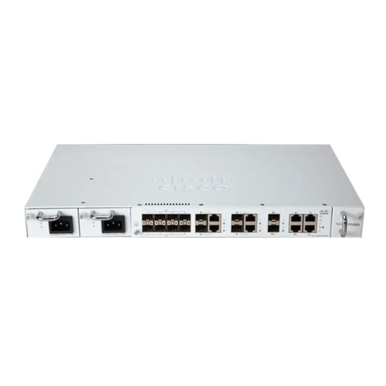
Page 13: Front Panel
Table 1: Cisco Catalyst PON Series OLT Models and Description Model Description CGP-OLT-8T Cisco Catalyst PON Series OLT with 8xPON port, 4x1 G combo port, and 2x10 G SFP+ module uplink slot. CGP-OLT-16T Cisco Catalyst PON Series OLT with 16xPON port, 4x1 G combo port, and 2x10 G SFP+ module uplink slot. -
Page 14: Rear Panel
2.466 Gbps downstream and 1.244 Gbps upstream. Console Port The console port connects the Cisco Catalyst PON Series OLT to a PC running Microsoft Windows or to a terminal server and uses the RJ-45 crossover cable. The RJ-45 console port connection uses the supplied RJ-45-to-DB-9 female cable. -
Page 15: Power Supply
Note This functionality is currently disabled. Power Supply The Cisco Catalyst PON Series OLT chassis has redundant power supply slots that operate with one or two power supply modules. The chassis supports field-replaceable AC-input and DC-input power supply modules. Note Hybrid power supply plugs are not supported. -
Page 16: Leds
Output Power (Watts) -36 to -72VDC (with extended range upto -75VDC) Voltage differential between inputs is unlimited. LEDs You can use LEDs to monitor the activity and performance of Cisco Catalyst PON Series OLT. Table 2: System LEDs Color Indication... -
Page 17: Cisco Catalyst Pon Series Ont Overview
In the upstream direction, a Cisco Catalyst PON Series ONT is connected to the optical splitter through the PON port. The data, voice, and video signals from end user's devices are sent to the Cisco Catalyst PON Series ONT. Using the uplink ports on the Cisco Catalyst PON Series ONT, these signals are converted into electrical signals and transmitted over optical fibers to the Cisco Catalyst PON Series OLT. -
Page 18: Cisco Catalyst Pon Series Ont Models
Introduction to Passive Optical Network Cisco Catalyst PON Series ONT Models Cisco Catalyst PON Series ONT provides 1xPON port, 4x1 G 10/100/1000 PoE port, and 1xUSB Type A port with 2xForeign Exchange Station (FXS) port, and 1xcoaxial cable television (CATV) port, which is optional. - Page 19 PON port Not available on all ONT models Not available on all ONT models Figure 7: Front panel of CGP-ONT-4TVCW Power button 1 G ports DC power connector USB Type A port Cisco Catalyst PON Series Switches Hardware Installation Guide...
-
Page 20: Rear Panel
Introduction to Passive Optical Network Rear Panel FXS ports CATV port Rear Panel The section describes the rear-panel components of a Cisco Catalyst PON Series ONT. Figure 8: Rear panel of CGP-ONT-1P Lock slot Grounding connector AC power connector Figure 9: Rear Panel of CGP-ONT-4PVC... -
Page 21: Top Panel
Introduction to Passive Optical Network Top Panel Figure 10: Side Panel of CGP-ONT-4TVCW Light button Reset button WiFi button Top Panel This section describes the top-panel components of CGP-ONT-4TVCW. Cisco Catalyst PON Series Switches Hardware Installation Guide... -
Page 22: Power Led
Introduction to Passive Optical Network Top Panel Figure 11: Top panel of CGP-ONT-4TVCW Power LED CATV LED PON LED 2.4 GHz LED 1 G LED 5 GHz LED FXS LED Cisco Catalyst PON Series Switches Hardware Installation Guide... -
Page 23: Ports
A USB type A console port is provided for log and configuration file management. CATV Port The CATV port uses a coaxial cable. LEDs You can use the LEDs to monitor the activity and performance of Cisco Catalyst PON Series ONT. Table 5: LEDs on CGP-ONT-1P, CGP-ONT-4P, CGP-ONT-4PV, and CGP-ONT-4PVC Color Indication Green (solid) Normal power from power supply. - Page 24 Loss in optical signal power. PON module is not ready. Link is up but is not transmitting 1 G (1–4) Green (solid) data. Green (flashing) Link is up and transmitting data. Link is down. Cisco Catalyst PON Series Switches Hardware Installation Guide...
-
Page 25: Lock Slot
Lock Slot The Cisco Catalyst PON Series ONT has a lock slot on the rear panel. You can install an optional cable lock, such as the type that is used to secure a laptop computer, to secure the Cisco Catalyst PON Series ONT. - Page 26 Introduction to Passive Optical Network Cisco Catalyst PON Manager Overview Cisco Catalyst PON Series Switches Hardware Installation Guide...
-
Page 27: Installation
Read the wall-mounting instructions carefully before beginning installation. Failure to use the correct hardware or to follow the correct procedures could result in a hazardous situation to people and damage to the system. Statement 378 Cisco Catalyst PON Series Switches Hardware Installation Guide... -
Page 28: Safety Warnings
Contact the appropriate electrical inspection authority or an electrician if you are uncertain that suitable grounding is available. Statement 1024 Warning Only trained and qualified personnel should be allowed to install, replace, or service this equipment. Statement 1030 Cisco Catalyst PON Series Switches Hardware Installation Guide... - Page 29 Statement 1072 Warning No user-serviceable parts inside. Do not open. Statement 1073 Cisco Catalyst PON Series Switches Hardware Installation Guide...
-
Page 30: Box Contents
Statement 1076 Warning Hot surface. Statement 1079 Box Contents This section lists the contents of the shipping box. Cisco Catalyst PON Series OLT and Accessories Table 7: Cisco Catalyst PON Series OLT and Accessories Component Description Quantity Model CGP-OLT-8T... - Page 31 Mounting brackets to cabinet screws #10 Mounting brackets to cabinet screws #12 Pointer card Table 10: CGP-ONT-4TVCW and Accessories Component Description Quantity Model CGP-ONT-4TVCW Accessories RJ-45 to RJ-45 crossover cable Power adapter Pointer card Cisco Catalyst PON Series Switches Hardware Installation Guide...
-
Page 32: Installation Guidelines
• Humidity around the switch does not exceed 90 percent. • Altitude at the installation site is not greater than 5,000 feet (1524 meters). • For 10/100/1000 fixed ports, the cable length from the Cisco Catalyst PON Series ONT to a connected device cannot exceed 328 feet (100 meters). -
Page 33: Attaching The Rack-Mounting Bracket And Mounting A Olt On A Rack
Use the Phillips head screwdriver and attach the 19-inch rack-mounting bracket to an OLT using the mounting-bracket screws. Follow the same steps to attach the second bracket to the other side. Figure 12: Attaching Rack-Mounting Brackets on a CGP-OLT-8T 6xMounting-bracket screw Front-mounting position 2xRack-mounting bracket Cisco Catalyst PON Series Switches Hardware Installation Guide... -
Page 34: Installing Sfp Or Sfp+ Modules
Installing SFP or SFP+ Modules Each Cisco module has an internal serial electrically erasable programmable read-only memory (EEPROM) that is encoded with security information. This encoding provides a way for Cisco to identify and validate that the module meets the requirements for the switch. -
Page 35: Removing An Sfp Or Sfp+ Module
The system ground provides additional grounding for EMI shielding requirements and grounding for the low voltage supplies (DC-DC converters) on the modules. You must observe the following system grounding guidelines for your chassis: Cisco Catalyst PON Series Switches Hardware Installation Guide... -
Page 36: Required Tools And Equipment
Procedure Step 1 Secure the grounding lug to the OLT with an M4 screw. Ensure that the grounding lug and the grounding wire do not interfere with other hardware or rack equipment. Cisco Catalyst PON Series Switches Hardware Installation Guide... - Page 37 Figure 15: Connecting the System Ground for CGP-OLT-16T 1xM4 screw Grounding wire with grounding lug Step 2 Prepare the other end of the grounding wire with a ring lug, and secure it to the rack with a screw. Cisco Catalyst PON Series Switches Hardware Installation Guide...
-
Page 38: Connecting To The Power Source
Prior to connecting the power supply to a power source, ensure that the chassis is properly grounded. Procedure Step 1 Plug the power cable into the power connector on the power supply unit of the OLT. Figure 16: Connecting an AC Power Cable to CGP-OLT-8T Cisco Catalyst PON Series Switches Hardware Installation Guide... -
Page 39: Connecting To A Dc Power Source
Turn off the power at the circuit breakers for the portions of the DC grid power that you are connecting to, and verify that all the LEDs on the DC grid power supplies are off. Cisco Catalyst PON Series Switches Hardware Installation Guide... -
Page 40: Setting Up The Olt
On the console of the connected device, enter the following default credentials and press Enter: • username: admin • password: 123456 Installing an ONT The following sections provide information about the various tasks that comprise the process of installing an ONT. Cisco Catalyst PON Series Switches Hardware Installation Guide... -
Page 41: Placing The Ont On A Table Or Shelf
Place the mounting bracket with the side containing the text This side is close to the chassis to the base of the ONT. b) Use the Phillips head screwdriver and attach the mounting bracket to the ONT using the mounting bracket screws. Cisco Catalyst PON Series Switches Hardware Installation Guide... - Page 42 CGP-ONT-1P 4xMounting-bracket screw Mounting bracket Step 5 Place the bottom of the ONT over the screws on the wall and slide the ONT down until the screws fit snugly into the slots. Cisco Catalyst PON Series Switches Hardware Installation Guide...
-
Page 43: Attaching The Rack-Mounting Bracket And Mounting An Ont On A Rack
Insert the ONT into the rack and align the bracket in the rack. Use the rack-mounting screws to secure the ONT in the rack. To prevent airflow restriction, allow clearance around the ventilation openings to be at least: 3 in. Warning (7.6 cm). Statement 1076 Cisco Catalyst PON Series Switches Hardware Installation Guide... -
Page 44: Connecting To An Ac Power Source
Verify that the power supply is receiving power by checking whether the PWR LED is green. If the LED does not turn on, check the power connections on the power supply and the power source. Note Cisco Catalyst PON Series Switches Hardware Installation Guide... -
Page 45: Setting Up An Ont
• username: cisco • password: cisco Installing Cisco Catalyst PON Manager Before you begin To avoid software conflicts during the installation of Cisco Catalyst PON Manager, turn off all the antivirus applications on your device. Procedure Step 1 Obtain the network management software installation package from Cisco. - Page 46 Click Next to begin the installation. The License Agreement page is displayed. Step 4 Click Yes to accept the end user license agreement and continue with the installation. Click Print to print the agreement. Cisco Catalyst PON Series Switches Hardware Installation Guide...
- Page 47 Installation Installing Cisco Catalyst PON Manager The Choose the folder to install page is displayed. Step 5 Click Browse to change the folder location. Click Next to continue with the installation. Cisco Catalyst PON Series Switches Hardware Installation Guide...
- Page 48 Installation Installing Cisco Catalyst PON Manager The Select Features page is displayed. Step 6 Click Next to start the installation. If the installation is successful, the installation complete page is displayed. Cisco Catalyst PON Series Switches Hardware Installation Guide...
- Page 49 Installation Installing Cisco Catalyst PON Manager Step 7 Click Finish to complete the installation. The server and client shortcut icons are created on the desktop. Cisco Catalyst PON Series Switches Hardware Installation Guide...
-
Page 50: Setting Up Cisco Catalyst Pon Manager
Setting Up Cisco Catalyst PON Manager Setting Up Cisco Catalyst PON Manager To set up Cisco Catalyst PON Manager, you need to start the PON Manager Server and then create a new user name and password in the PON Manager Client. -
Page 51: Creating A New User In Pon Manager Client
Step 1 Double-click on the PON Manager Client icon, if installed on the desktop or click the Windows Start button and navigate to Cisco Catalyst PON Manager > PON Manager Client. The login page is displayed. Cisco Catalyst PON Series Switches Hardware Installation Guide... - Page 52 Installation Creating a New User in PON Manager Client Step 2 In the Password field, enter the default password as cisco. Step 3 Click Login. A pop-up message is displayed asking you to change the user name and password. Cisco Catalyst PON Series Switches Hardware Installation Guide...
- Page 53 Installation Creating a New User in PON Manager Client Step 4 Click OK to continue. The Change Default User dialog box is displayed. Cisco Catalyst PON Series Switches Hardware Installation Guide...
- Page 54 Step 7 In the Confirm Password field, reenter the new password. Step 8 To save the changes, click Apply. A confirmation message is displayed. Step 9 Click OK. The login page is displayed. Cisco Catalyst PON Series Switches Hardware Installation Guide...
-
Page 55: Remove And Replace Field-Replaceable Units
Only trained and qualified personnel should be allowed to install, replace, or service this equipment. Statement 1030 Removing the Fan Module Before you begin • See Installation Guidelines. • Ensure that you have the following tools and accessories available: • Phillips head screwdriver • Antistatic mat Cisco Catalyst PON Series Switches Hardware Installation Guide... - Page 56 OLT. Step 3 Place your other hand underneath to support the bottom of the fan module and then remove the fan module completely. Figure 22: Removing the Fan Module from the CGP-OLT-8T Cisco Catalyst PON Series Switches Hardware Installation Guide...
-
Page 57: Installing A Fan Module
Removing and Replacing the Power Supply Module The location of the power supply module depends on the type of the Cisco Catalyst PON OLT: • Front panel of CGP-OLT-8T • Rear panel of CGP-OLT-16T Installation Guidelines •... -
Page 58: Removing And Installing Power Supply Blank Cover
Use the Phillips head screwdriver and loosen the installation screws on the power supply module blank cover. Step 2 Use both hands to remove the power supply module blank cover. Step 3 Store the power supply module blank cover in a safe location for future use. Cisco Catalyst PON Series Switches Hardware Installation Guide... -
Page 59: Installing A Power Supply Blank Cover
• For the DC-input power supply, loosen and unscrew the two nuts that connect the positive (+) DC power cable lug to the RTN terminal, and the negative (–) DC power cable lug to the NEG terminal. Remove the power cables from the power supply module. Cisco Catalyst PON Series Switches Hardware Installation Guide... - Page 60 Power supply module handle on the power supply module Figure 24: Removing the AC Power Cable from CGP-OLT-16T Captive installation screw on the power Power cable supply module Power supply module handle on the power supply module Cisco Catalyst PON Series Switches Hardware Installation Guide...
- Page 61 OLT. Step 5 Place your other hand underneath to support the bottom of the power supply module and then remove the module completely. Figure 25: Removing the Power Supply Module from CGP-OLT-8T Cisco Catalyst PON Series Switches Hardware Installation Guide...
-
Page 62: Inserting The Power Supply Module In An Olt
Figure 26: Removing the Power Supply Module from CGP-OLT-16T Caution If you intend to operate the Cisco Catalyst PON Series OLT without installing another power supply in the empty slot, you must reinstall the blank cover over the empty power supply slot to ensure proper airflow in the system and for safety reasons. - Page 63 You can proceed with either of the following actions: • Connect an AC power source, see Connecting to an AC Power Source. • Connect a DC power source, see Connecting to a DC Power Source. Cisco Catalyst PON Series Switches Hardware Installation Guide...
- Page 64 Remove and Replace Field-Replaceable Units Inserting the Power Supply Module in an OLT Cisco Catalyst PON Series Switches Hardware Installation Guide...
-
Page 65: Troubleshoot
• Cisco Catalyst PON Series ONT Troubleshooting, on page 58 Troubleshooting Common Issues The following section provide information about how to troubleshoot common issues in the Cisco Catalyst PON Series Switches. Bad or Damaged Cable Always examine the cable for marginal damage or failure. A cable might appear physically good, but it could corrupt packets as a result of subtle damage to the wiring or connectors. -
Page 66: Link Status
The following sections describe how to troubleshoot issues relating to the Cisco Catalyst PON Series OLT. SFP and SFP+ Module Use only Cisco SFP or SFP+ modules. Each Cisco module has an internal serial EEPROM that is encoded with security information. This encoding provides a way for Cisco to identify and validate that the module meets the requirements for the switch. -
Page 67: Fan Module
An alarm notification sent through the Cisco Catalyst PON Manager when a pluggable fan module is faulty. Make sure you replace the fan module within the following time period: • Replace the fan module within one week if one alarm notifications occur in the Cisco Catalyst PON Manager. -
Page 68: Cisco Catalyst Pon Series Ont Troubleshooting
Cisco Catalyst PON Series ONT Troubleshooting Finding the Cisco Catalyst PON ONT Serial Number If you contact Cisco Technical Assistance, you must know the Cisco Catalyst PON ONT serial number. Figure 28: Serial Number Location Cisco Catalyst PON Series Switches Hardware Installation Guide... -
Page 69: Appendix A Technical Specifications
Cisco Catalyst PON Series OLT Technical Specifications, on page 59 • Cisco Catalyst PON Series ONT Technical Specifications, on page 60 Cisco Catalyst PON Series OLT Technical Specifications The following sections provide information about the Cisco Catalyst PON Series OLT. Physical Specifications CGP-OLT-8T Physical Dimensions Weight 9.92 lbs (4.5 kg) -
Page 70: Power Requirements
Power rating 55 W full load (CGP-OLT-8T) 70 W full load (CGP-OLT-16T) Cisco Catalyst PON Series ONT Technical Specifications The following sections provide information about the Cisco Catalyst PON Series ONT. Physical Specifications CGP-ONT-1P Physical Dimensions 0.8 lbs (0.36 kg) -
Page 71: Environmental Specifications
Minimum ambient temperature for cold start is 32°F (0°C) Power Requirements Power Requirements 110 to 220 VAC, 1.1 A AC input voltage Power rating 36W (CGP-ONT-1P) 72 W (CGP-ONT-4P, CGP-ONT-4PV, and CGP-ONT-4PVC) 18W (CGP-ONT-4TVCW) Cisco Catalyst PON Series Switches Hardware Installation Guide... - Page 72 Technical Specifications Power Requirements Cisco Catalyst PON Series Switches Hardware Installation Guide...
-
Page 73: Appendix B Connector And Cable Specifications
The following sections provide information about the various connectors. 10/100/1000 Ports (Including PoE) All 10/100/1000 ports use standard RJ-45 connectors and Ethernet pinouts. Figure 29: 10/100/1000 Port Pinouts SFP Module Connectors Figure 30: Duplex LC Cable Connector Cisco Catalyst PON Series Switches Hardware Installation Guide... -
Page 74: Cables And Adapters
Each port must match the wavelength specifications on the other end of the cable, and the cable must not exceed the stipulated length. Copper 1000BASE-T SFP module transceivers use standard four twisted-pair, Category 5 cable of lengths up to 328 feet (100 meters). Cisco Catalyst PON Series Switches Hardware Installation Guide... -
Page 75: Cable Pinouts
The wire connected to the pin on the outside of the left plug should be a different color from the wire that is connected to the pin on the inside of the right plug. Cisco Catalyst PON Series Switches Hardware Installation Guide... -
Page 76: Console Port Adapter Pinouts
Switch Console Port (DTE) RJ-45-to-DB-9 Terminal Adapter Console Device Signal DB-9 Pin Signal Table 12: Console Port Signaling with a DB-25 Adapter Switch Console Port (DTE) RJ-45-to-DB-25 Terminal Adapter Console Device Signal DB-25 Pin Signal Cisco Catalyst PON Series Switches Hardware Installation Guide... - Page 77 Connector and Cable Specifications Connector and Cable Specifications Switch Console Port (DTE) RJ-45-to-DB-25 Terminal Adapter Console Device Signal DB-25 Pin Signal Cisco Catalyst PON Series Switches Hardware Installation Guide...
- Page 78 Connector and Cable Specifications Connector and Cable Specifications Cisco Catalyst PON Series Switches Hardware Installation Guide...
- Page 79 Cisco has more than 200 offices worldwide. Addresses and phone numbers are listed on the Cisco website at www.cisco.com/go/offices. Cisco and the Cisco logo are trademarks or registered trademarks of Cisco and/or its affiliates in the U.S. and other countries. To view a list of Cisco trademarks, go to this URL: https://www.cisco.com/c/en/us/about/legal/trademarks.html.