Advertisement
Quick Links
715 Peachtree Street NE
Atlanta, GA 30308
www.honeywell.com
3/30/2018
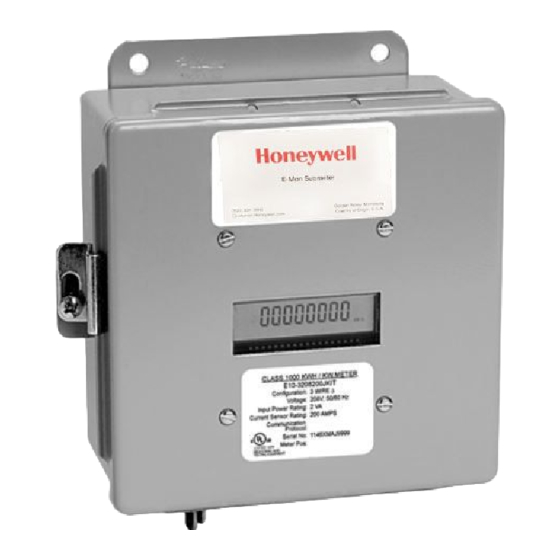
Honeywell E-Mon Class 1000 and or 2000 Meter Connections to IDR
E-Mon Class 1000 & 2000 meters include two modular jacks located at the top of the main circuit board.
The jack on the left (RJ-45, 8-pin) is used to connect the meter to the IDR ports 1 – 8 or 1 – 16 (500 feet
maximum cable length.) The jack on the right is for factory use only.
IDR is available in two RJ configurations IDR-8 and IDR-16
Connecting the Class 1000 and 2000 Meter to the IDR
NEVER USE THE JACKS LABELED "PORT 0" OR "PORT 2 or ETHERNET" TO CONNECT A METER TO
THE IDR. Connect Class 1000 and 2000 meter's to the IDR meter input jacks #1-8 using 8 conductor RJ-
45 patch cables (500 foot maximum length.)
IDR-16 - If the IDR is an IDR-16, connect the additional meters to the IDR jacks #9- 16 on the circuit board
using 8-conductor RJ-45 patch cable (500 foot maximum length.) Wiring for all E-Mon cables must be
straight through. See Appendix A for correct cable configuration.
Advertisement

Related Manuals for Honeywell E-Mon Class 1000


Summary of Contents for Honeywell E-Mon Class 1000
- Page 1 Honeywell E-Mon Class 1000 and or 2000 Meter Connections to IDR E-Mon Class 1000 & 2000 meters include two modular jacks located at the top of the main circuit board. The jack on the left (RJ-45, 8-pin) is used to connect the meter to the IDR ports 1 – 8 or 1 – 16 (500 feet maximum cable length.) The jack on the right is for factory use only.
- Page 2 RS-485 Serial Connections: Method 1: Modular Plug Method This method requires using 4 stranded conductors inside a cable that is fitted with an RJ-11 type plug for 4- conductor modular systems at each end of the cable. 1. Plug the 4-wire RJ-11 cable/plug assembly into either PORT 0 or PORT 2 of the IDR. 2.
- Page 3 RS-485 Serial Connections: Method 2: Terminal Block Method IDRs may also be daisy-chained using a 3-conductor cable. Instead of using the two modular jacks for the RS-485 daisy chain, you can use Port 1, between the RJ11 jacks. 1. Daisy-chain the IDRs by connecting: - All HI (+) terminals together** - All LO (-) terminals together** - The SH terminals are not used as the third wire ground is a floating ground.
- Page 4 Setting the EZ7 ID The IDR’s EZ7 ID code’s, 1A, 1E, 1I, and etcetera, must be set by the installer with the menu and select buttons. Duplicate EZ7 addresses for example two 1A EZ7 ID’s will not communicate on the same RS485 network.
-
Page 5: Appendix A - Cable Configurations
Appendix A - Cable Configurations Four-conductor cables for the IDR RS-485 communication (4,000 foot maximum.) RJ11 Plug Pinout Pin 1 Not Used Pin 2 Black Pin 3 Red (Ground) Pin 4 Green (+ High) Pin 5 Yellow (- Low) Pin 6 Not Used... - Page 6 RJ-45 eight-conductor patch cables for Class 1000 and 2000 meter to IDR inputs 1 through 16 (500 foot maximum.) NOTE: All cables are wired pin-to-pin (straight through) as shown above. Example supplier of RJ-45 patch cables: http://www.staples.com/Belkin-10-Cat6-RJ45-RJ45-Patch-Network-Cable-Black/product_IM1QZ4626 See the IDR installation manual for complete instructions.