
Related Manuals for Motorola V.3600


Summary of Contents for Motorola V.3600
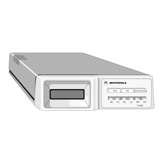
- Page 1 V.3600 Modem User’s Guide TALK/DATA V.3600 Motorola ISG Part No. T0097, B 20 Cabot Boulevard Model V.3600 Mansfield, Massachusetts 02048 February, 1999 © 1998 Motorola...
- Page 2 Updates Check Motorola Web sites as listed under “Service and Support” at the end of this User’s Guide for the latest updates to our products. V.3600...
-
Page 3: Regulatory Information
If your equipment continues to disrupt the network the telephone company may temporarily disconnect service. If this occurs you will be informed of your right to file a complaint with the FCC. V.3600... - Page 4 FCC Part 15 Declaration Of Conformity FOR HOME OR OFFICE USE Model Name: V.3600, 115 VAC version only Caution This equipment uses, generates, and can radiate radio frequency energy interfering with radio communications if not installed and used according to the instruction manual.
- Page 5 To comply with FCC regulations it is necessary to use shielded computer cables with your installation. FOR OFFICE USE ONLY Model Name: V.3600, all other versions Caution This equipment uses, generates, and can radiate radio frequency energy interfering with radio communications if not installed and used according to the instruction manual.
- Page 6 For their own protection users should ensure that the electrical ground connections of the power utility, telephone lines and internal metallic water pipe system, if present, are connected together. This precaution may be particularly important in rural areas. V.3600...
- Page 7 Ringer Equivalence Numbers of all the devices does not exceed five (5). CANADIAN EMISSION REQUIREMENTS (V.3600, 115 Vac) This Class B digital apparatus meets all requirements of the Canadian Interference-Causing Equipment Regulations.
-
Page 9: Table Of Contents
DC Power Connection ..............DTE Connection..................Telephone Line Connection ..............Dial Mode: PSTN Connection (DIAL jack) ........Leased Line Connection (TELSET/LEASED LINE Jack)....Shelf-Mount RM16M V.3600 Installation ........... Chapter 3. Getting Started Option Selection ................... Power-Up ....................Placing a Call .................. - Page 10 Serial Port Ring Indicator (Pin 22) — \R ........5-21 Request to Send / Clear to Send — &R .......... 5-21 DTE Controlled Fallback Rate (Pin 23) — *FB ......5-22 General Commands ................5-22 Changing from Data Mode to Command Mode — +++....5-22 V.3600...
- Page 11 Powerup Option Set — &Y ............5-38 Load Factory Options — &Fn ............5-39 Reset to Stored Configuration — Z ..........5-39 View Configuration Profiles/Received Signal Options &V .... 5-40 Storing a Telephone Command Line — &Zx=n, *CNx,n, *ND ..5-40 V.3600...
- Page 12 Remote Digital Loopback with Self Test — &T7 ......Test Pattern — %T ................Bilateral Digital Test Enable / Disable — *DG ....... DTE Controlled Remote Digital Loopback (Pin 21) — *RD ..DTE Controlled Local Analog Loopback (Pin 18) *LA ....V.3600...
- Page 13 Display User Status — $S? .............. 8-11 Verify User Information — $In, $IBn ..........8-11 Request Superuser Privilege — $S=pw .......... 8-11 Local Logon Command — $n=pw ..........8-11 Local Logoff Command — $$ ............8-11 Remote Logon Procedure — $n=pw ..........8-12 V.3600 xiii...
- Page 14 Pause Interval for Comma — S8 ............ 10-6 Carrier Detect Time — S9 .............. 10-6 Lost Carrier Detect Time — S10 ............ 10-6 DTMF Tone Duration — S11 ............10-6 Escape Sequence Pause — S12 ............10-7 S13....................10-7 Bit Mapped — S14 ................10-8 V.3600...
- Page 15 Link Speed Status — S67 ............... 10-20 S68 ....................10-20 DCE Independent Speed — S69 ............. 10-21 Operating Mode — S70 ..............10-22 Operating Mode Status — S71 ............10-22 Bit Mapped — S72 ................10-23 Password Timeout — S73 ............... 10-23 V.3600...
- Page 16 Request List of Version — RLV ............. 11-11 Modem Options Command — PRO xxx;yy;0;0......11-11 Save Current Settings — PRK ............11-13 Restore Factory Settings — PRP n ..........11-13 Request List of Stored Options — RLO xxx; yy ......11-14 Options ....................11-15 V.3600...
- Page 17 Appendix C. Hardware Options Jumper Option Selection ..............Removing the Cover ................Ground Option Jumper ..............Replacing the Cover ................Appendix D. Fault Isolation Procedure Fault Isolation Procedure ..............Telephone Interface ................. Standard Phone................. Modem and Telephone Line Check ............V.3600 xvii...
- Page 18 E-31 Appendix F. ASCII and EBCDIC Characters Appendix G. Abbreviations and Acronyms Appendix H. Flash Upgrade What You Need ..................Steps For Downloading ................ Troubleshooting ..................Appendix I. Country-Specific Parameters Service and Support Motorola Limited Hardware Warranty Index V.3600 xviii...
-
Page 19: Chapter 1. Introduction
Shelf-Mount Units This User’s Guide supports the desktop and shelf-mount versions of the V.3600. Operation and function are generally the same for both, but when there is a difference, the information primarily supports the desktop unit. Installation for each version is described in Chapter 2. -
Page 20: Features
Introduction Features The V.3600 is a flexible telecommunications tool that offers the following standard features. Data Mode • Full-duplex operation on two-wire public connections or two-wire or four-wire private telephone connections with two-wire public automatic or manual backup • 300, 1200, 2400, 4800, 7200, 9600, 12000, 14400, 16800, 19200, 21600, 24000, 26400, 28800, 31200, 33600 bps DCE data rates •... -
Page 21: Fax Mode
V.17 • Autoanswer under software control • Automatic fax/data detection Software Software operates the features of the V.3600. Communications Software You must have communications software to transfer data. After installing the modem, consult your communications software user's manual for information on the software, commands, and features. -
Page 22: Description
LCD, the AT command set, or the V.25 bis command set. The 230.4 kbps DTE speed is available, but the V.3600 will not autobaud to 230.4 kbps. With the modem set for 115.2 kbps, enter AT\J2 to enable the speed and enter AT\J3 to disable it. - Page 23 Introduction The V.3600 rear panel has an EIA-232 DTE connector, an 8-pin TELSET/LEASED LINE jack, an 8-pin DIAL jack, the power switch, fuse, and cord (Figure 1-2). 3/16 TELSET AMP S.B. LEASED LINE DIAL 115 VAC 60 HZ 1/4 AMP Figure 1-2.
-
Page 24: Rm16M Unit
The shelf-mount RM16M unit (Figure 1-3) has edge connectors that insert into the shelf backplane. The shelf backplane performs the same functions as the standalone rear panel. Refer to the “Shelf-Mount RM16M V.3600 Installation” section on page 2-9. V.3600 Figure 1-3. RM16M Version of the V.3600... -
Page 25: Chapter 2. Installation
If the modem is equipped for 12-60 VDC power input, connect the power to the terminal block attached to the modem back panel. A chassis ground connection is also supplied on the terminal block. V.3600... -
Page 26: Dte Connection
DTE Connection The DTE connector is a 25-pin D-series type conforming to EIA-232 specifications. You must use a shielded DTE cable to comply with EMC requirements. Pin signals are shown in Figure 2-2 and are described in Table 2-1. V.3600... - Page 27 Installation Figure 2-2. Digital Interface Signals V.3600...
- Page 28 -12 Volts -12 voltage reference * Modem options may force these signals on or cause them to be ignored. ** Refer to Appendix C, Hardware Options. † This function can be disabled or its logic sense reversed by hardware straps. V.3600...
- Page 29 Test Mode Indicates the modem is in a test mode. * Modem options may force these signals on or cause them to be ignored. ** Refer to Appendix C, Hardware Options. † This function can be disabled or its logic sense reversed by hardware straps. V.3600...
-
Page 30: Telephone Line Connection
The public switched telephone network (PSTN) is a two-wire dial network. Modems are registered with the Federal Communications Commission (FCC) for direct connection to the PSTN. The label on the chassis bottom gives the FCC registration number and other information required for network operation. V.3600... -
Page 31: Leased Line Connection (Telset/Leased Line Jack)
Figure 2-3. Dial-up Connection (115 Vac Model) Leased Line Connection (TELSET/LEASED LINE Jack) Private or leased lines use four-wire or two-wire lines. In this mode, the user configures the unit for four-wire or two-wire operation, depending on the private line service used. V.3600... - Page 32 Tx and Rx data. For a 4-wire Leased-line connection, Pins 1 and 2 are used for Tx, and Pins 7 and 8 are used for Rx. 5. For connector pin-outs, refer to Appendix B. Figure 2-4. Leased Line Connection (115 Vac Model) V.3600...
-
Page 33: Shelf-Mount Rm16M V.3600 Installation
Installation Shelf-Mount RM16M V.3600 Installation Go to Appendix C, Hardware Options to check the board options before installation. Shelf-mount RM16M V.3600s should be installed or replaced by personnel familiar with shelf-mount installation. The unit has an edge connector that inserts into a receptacle located on the backplane and power bus. -
Page 35: Chapter 3. Getting Started
A power-up procedure is not required. Turn on the modem using the ON/ OFF power switch on the rear panel. The modem is factory configured to operate in most public switched telephone applications. If you have stored a desired option set it will be automatically be restored at power-up. V.3600... -
Page 36: Placing A Call
Enter, or enter ATDSn where n equals one of the stored telephone number locations 1-9. The modem dials the number--either pulse or tone, whichever is currently in effect--and takes the role of the originate modem. Refer to the “Dial Commands” section on page 5-13 for additional dialing commands. V.3600... -
Page 37: Answering A Call
1) Press the TALK/DATA pushbutton. DO YOU WANT TO DISCONNECT will be displayed. 2) Answer YES. Ending a Call from a Terminal with the AT Command 1) Enter +++ and the modem will enter command mode. 2) Enter ATH and the modem will terminate the call. V.3600... -
Page 38: Reasons For Call Termination
A connection occurred at a rate less than minimum. Security Password Maximum password entry attempts exceeded. Failure Security Callback Security callback is enabled and a new remote connection is established. The modem disconnects and places a call to the programmed number. V.3600... - Page 39 Description Condition Signal Quality Leased line operation with dial backup enabled; extended loss of carrier or 4 unsuccessful retrains in 3 minutes causes dial backup. Test Mode entered Certain test modes require call termination. Modem power is turned off. V.3600...
-
Page 41: Chapter 4. Front Panel Operation
LCD, through the use of the front panel remote configuration feature. LED Descriptions The V.3600 LED indicator functions are as follows: • TR (Terminal Ready). TR lights when the DTE asserts Data Terminal Ready. This signal is input on pin 20 (CCITT V.24/108.2). -
Page 42: Lcd Menus
Front Panel Operation LCD Menus The V.3600 has seven main LCD menus that support modem operations. Table 4-1 lists them, in the following sequence: • MODEM STATUS • DIAL STORED NUMBER • DISPLAY STATUS • SELECT TEST • MODIFY CONFIGURATION •... - Page 43 INITIATE, &T8 LOOP WITH TP EXIT (Online test) LOCAL DIGITAL INITIATE, &T3 LOOP † EXIT When modem is not online, the display flashes and shows the status from the last connection. † Modem must be online with protocols disabled. V.3600...
- Page 44 %B14 21600 %B13 19200 %B12 16800 %B11 %B10 14400 12000 7200 9600 9600U ** 4800 2400 1200 DTE SPEED Lease line only. ** 9600U is only valid for V.32 bis modulation. † Modem must be online with protocols disabled. V.3600...
- Page 45 V.32 FAST TRAIN ENABLE *FT1 DISABLE AUTO RETRAIN ENABLE DISABLE SQ AUTO RATE HIGH BER MED BER LOW BER DISABLED TRANSMIT INTERNAL &X CLOCK EXTERNAL &X1 SELECT RECEIVE &X2 Lease line only. ** 9600U is only valid for V.32 bis modulation. V.3600...
- Page 46 \N, \N1, \N2, \N3 ENABLE \N2, \N3, PROTOCOL \N6, \N7 DISABLE \N, \N1, \N4, \N5 PROTOCOL ENABLE \N3, \N5, FALLBACK \N6, \N7 DISABLE \N, \N1, \N2, \N4 DATA COM- DISABLE PRESSION NORM Lease line only. † Dial line only. V.3600...
- Page 47 3, 4, 5, 6 ASYNC &M DTE RATE 300, (Async) 600,1200, 2400, 4800, 7200, 9600, 12000, 14400, 16800, 19200, 21600, 24000, 26400, 28800, 31200 33600 38400 57600, 115200 CHAR SIZE 7 BIT (Async) 8 BIT PARITY (Async) NO, EVEN, V.3600...
- Page 48 &S1 FORCED &S HIGH OFF 5 SEC &S2 DISCON- NECT FOLLOWS &S3 DCD STATE NORMAL &C1 FORCED &C HIGH OFF 5 SEC &C2 DISCON- NECT FOLLOWS &C3 REMOTE CTS STATE NORMAL &R FORCED &R1 HIGH &R2 FOLLOWS CTS=RTS &R9 V.3600...
- Page 49 PAUSE DELAY 1, 2, 3, 4, 8, 16, 32 SEC CALL TIMEOUT 15, 30, 45, 60, 75, 90, 105, 120 ANSWER RING 1, 2, 4, 8, 16 --- AUTOCALLBACK ENABLE, DISABLE CHANGE VOLUME L1, L2 SPEAKER CONTROL HIGH OPERATION? V.3600...
- Page 50 PASSWORD? PASS- FEA- WORD TURES? ENTER REMOTE ENTER CONFIGURA- REM CFG TION PASS- WORD EXIT REMOTE EXIT &T CONFIGURA- TION CHANGE FRONT ENTER PANEL PASS- PASS- WORD WORD * ACTIVATE SECURITY Password of 0000 disables front panel security. 4-10 V.3600...
-
Page 51: Front Panel Security
YES makes the modem accept the displayed password. • Pressing TALK/DATA while the cursor is on the first password character aborts password entry. When the cursor is on any other character, this button makes the cursor move to the first character. V.3600 4-11... -
Page 53: Chapter 5. At Commands
• Test (Chapter 7) • Security (Chapter 8) • Fax (Chapter 9) • S-registers (Chapter 10) Operation Modes In asynchronous operation, the modem functions in one of these modes: • Offline Command Mode • Online Command Mode • Data Mode V.3600... -
Page 54: Sending Commands To The Modem
Each command statement is made up of characters, numbers, and keyboard symbols such as the & and % signs. Commands must be written in a specific form so the modem recognizes and follows the instruction. V.3600... -
Page 55: Creating A Command Statement - At
• The command buffer can hold 80 characters. • Use the backspace or delete key to erase the last character. Even though the initial AT code must be all upper or lower case, characters that follow can be any mix of upper and lower case. V.3600... -
Page 56: Monitor Display
It automatically reexecutes the command without retyping. The return key does not need to be pressed. Example: The ATD5551212 command has been executed, and the phone is busy. To repeat the instruction type A/. Do not use AT before this command: AT empties the buffer. V.3600... -
Page 57: Numbered Commands
Bold text indicates command parameter defaults. Response Commands The modem communicates with the operator through response messages. These appear on the monitor or a computer printout to show the result of the command or action executed. Response messages can appear as words or numbers. V.3600... -
Page 58: Digit / Word Selection - V
DTE rate. Command Operation Disables negotiation displays Enables negotiation displays Displays DCE link rate only Connect Message Codes — \V The V.3600 AT\V command provides the following connect message options Command Operation AT\V CONNECT DTE rate AT\V1... -
Page 59: Call Progress / Connect Speed Messages X
If a dial tone is not detected within 5 seconds, the modem sends a NO DIALTONE message and hangs up. The modem does not detect a busy situation in this mode. V.3600... -
Page 60: Number Code Application - *Rc
This option selects either of two commonly used number code sets. Command Code Set Number Operation Standard 4800 bps 9600 bps *RC1 Alternate 4800 bps 9600 bps Note Asterisks in AT commands are part of the command and do not indicate footnotes. V.3600... -
Page 61: Response Number Codes / Messages
DTE rate 14400 bps CONNECT 16800 DTE rate 16800 bps CONNECT 19200 DTE rate 19200 bps CONNECT 21600 DTE rate 21600 bps CONNECT 24000 DTE rate 24000 bps CONNECT 26400 DTE rate 26400 bps CONNECT 28800 DTE rate 28800 bps V.3600... - Page 62 V.42 bis 21600 bps connection V42bis CONNECT 24000/ V.42 bis 24000 bps connection V42bis CONNECT 26400/ V.42 bis 26400 bps connection V42bis CONNECT 28800/ V.42 bis 28800 bps connection V42bis CONNECT 31200/ V.42 bis 31200 bps connection V42bis 5-10 V.3600...
- Page 63 V.42 26400 bps connection CONNECT 28800/V42 V.42 28800 bps connection CONNECT 31200/V42 V.42 31200 bps connection CONNECT 32000/V42 V.42 32000 bps connection CONNECT 33600/V42 V.42 33600 bps connection CONNECT 38400/V42 V.42 38400 bps connection CONNECT 57600/V42 V.42 57600 bps connection V.3600 5-11...
- Page 64 MNP5 230400 bps connection MNP5 CONNECT 300/MNP MNP 300 bps connection CONNECT 600/MNP MNP 600 bps connection CONNECT 1200/MNP MNP 12000 bps connection CONNECT 2400/MNP MNP 24000 bps connection CONNECT 4800/MNP MNP 4800 bps connection CONNECT 7200/MNP MNP 7200 bps connection 5-12 V.3600...
-
Page 65: Dial Commands
To dial a number, for example 555-1212, insert the D command in the dialing sequence. AT D 555-1212 The modem dials the number, either pulse or tone, whichever is in effect, and takes the role of the originate modem. V.3600 5-13... -
Page 66: Tone Dialing - T
2 second delay (or the value in register S8). AT D P 9, 1-800-554-1000 Here the modem pulse dials a 9, pauses for the telephone system to switch to an outside line, then dials the phone number. Comma pauses may be inserted consecutively if desired. 5-14 V.3600... -
Page 67: Wait For Second Dial Tone - W
The modem will dial the telephone number entered but will not attempt to train when the remote service answers the call. This is used to retain control so that further dialing tones may be entered with the following: AT DTn; where n= additional tones to be sent. V.3600 5-15... -
Page 68: Wait For 5 Seconds Of Silence
AT D (number); The ; modifier recalls the command mode and prevents the modem from training. The remote site must be answered by the telephone for the voice call to be successful. 5-16 V.3600... -
Page 69: Switching From Voice To Data
If the modem is set to respond to DTR the DTR signal must be on for autoanswer to work. Caller ID — *ID If the telephone company is providing Caller ID services to the local phone line, the V.3600 can report Caller ID to the DTE. V.3600 5-17... -
Page 70: Distinctive Ring - *Dr
Distinctive Ring — *DR If the telephone company is providing distinctive ring service to the local phone line, the V.3600 can report the type of ring to the DTE. data communications software package must allow distinctive ring. Caller ID and Distinctive Ring are compatible only with USA standards. -
Page 71: Terminal Interface Commands
&C2 DCD on except for 5 seconds after disconnect &C3 DCD follows RTS on remote modem (simulated switched carrier V.13). Note AT&C3 is used to simulate switched carrier operation. V.3600 5-19... -
Page 72: Data Set Ready - &S
DTR goes from on to off. In dial line mode the modem disconnects; in leased line, the modem retrains. Note If DTR controls dialer is selected, selecting DTR active will cause an autodial after an off-to-on transition of DTR. 5-20 V.3600... -
Page 73: Serial Port Ring Indicator (Pin 22) - \R
Note RTS/CTS delay is not valid in buffered mode or with error control enabled. Note With &R2 selected, XON/XOFF is the only valid method of flow control and &C and &C1 are the only valid carrier detect options. V.3600 5-21... -
Page 74: Dte Controlled Fallback Rate (Pin 23) - *Fb
Type AT without a carriage return. If the screen shows AT character, echo is correct. Proceed with other commands as desired. If the screen shows AATT, enter the E command to correct the double characters or disable character echo by the modem. 5-22 V.3600... -
Page 75: Online Character Echo - F
If H3 (the fast command) is entered, the H command will hang up much more rapidly at those speeds. Command Operation The modem hangs up. Forces modem off hook Sets H command to normal hangup procedure (long space, cleardown, protocol) Sets H command to fast hang up V.3600 5-23... -
Page 76: Eprom Check - I
(CRC) in hexadecimal form. Enter the I3 command to request the product version. Command Operation Request product code Request EPROM checksum value Request product version Returns Motorola V.3600 Last disconnect reason Speaker Volume L The L commands offer three volume levels. Command Operation L, L1, L2... -
Page 77: Return Online - O
Command Operation &G No guard tone &G1 550 Hz guard tone &G2 1800 Hz guard tone Asynchronous / Synchronous Mode Selection — &M The &M commands select synchronous or asynchronous operation and synchronous dial method. V.3600 5-25... -
Page 78: Make / Break Dial Pulse Ratio - &P
Use the &P command for the dial pulse to be on for 39% and off for 61% of one cycle. Use the &P1 command for the dial pulse to be on for 33% and off for 67% of one cycle. Command Operation &P 39% : 61% US and Canada &P1 33% : 67% 5-26 V.3600... -
Page 79: Synchronous Transmit Clock Source - &X
The *MM command sets the current modulation type to use when attempting to make a connection. Using this command automatically selects the maximum DCE speed (%B) for the selected modulation. Command Operation Automode (typically used on dial line) *MM1 V.21 *MM2 B103 *MM3 Reserved *MM4 B212A V.3600 5-27... -
Page 80: Maximum Dce Speed - %B
300 bps 1200 bps 2400 bps 4800 bps 9600 uncoded bps * 9600 bps 7200 bps 12000 bps 14400 bps %B10 600 bps %B11 16800 bps %B12 19200 bps %B13 21600 bps %B14 24000 bps %B15 26400 bps 5-28 V.3600... -
Page 81: Minimum Dce Speed - %L
7200 bps 12000bps 14400 bps %L10 600 bps %L11 16800 bps %L12 19200 bps %L13 21600 bps %L14 24000 bps %L15 26400 bps %L16 28800 bps %L17 31200 bps %L18 33600 bps Valid for V.32 bis modulation only V.3600 5-29... -
Page 82: Auto Retrain - %E
12 to 14 seconds from the last occurrence of a rate adaption. • After the modem drops data rate because of poor signal quality, the line must improve by approximately 2.5 dB before an increase in rate can occur. 5-30 V.3600... -
Page 83: Manual Rate Adaption - *Rr
Rate adaption to 21600 *RR9 Rate adaption to 24000 *RR10 Rate adaption to 26400 *RR11 Rate adaption to 28800 *RR12 Rate adaption to 31200 *RR13 Rate adaption to 33600 Product Revision Level %V The %V command displays the product revision level. V.3600 5-31... -
Page 84: Online Quick Reference - $H
Dial line operation only. The modem can be configured to disconnect upon loss or interruption of telephone line current. Command Operation Line current disconnect off *LC1 Line current disconnect short (8 ms) *LC2 Line current disconnect long (90 ms) 5-32 V.3600... -
Page 85: Disable At Command Set - *Nt
TELSET/LEASED LINE jack on the modem rear panel. Dialing is not necessary. When connected via leased line the modems will train and begin communicating with each other. The DIAL jack can be used to connect a 2-wire dial-up line for dial backup. V.3600 5-33... -
Page 86: 2-Wire Operation
AT Commands Note The V.3229, V.3227, V.3225, and V.3257 modems use V.33 as the modulation type. The V.3600 must be set up to V.33 to connect to these modems. 2-Wire Operation In 2-wire operation, the modem is a full-duplex modem able to operate over 2-wire leased or PSTN lines. -
Page 87: Dial Backup
When the LCD displays ON LINE again the dial line is disconnected. Note A diagnostic test initiated during dial backup mode terminates when the modem performs a leased line lookback. V.3600 5-35... -
Page 88: Dial / Leased Line - &L
Force originate *OR1 Force answer Leased Line Transmit Level — *TLn Command Operation *TLn Sets leased line TX level to n where n is a number 0 through 30 corresponding to a TX level of 0 to -30 5-36 V.3600... -
Page 89: Configuration Commands
The factory configurations are stored in ROM and cannot be changed by the user; they can be transferred to the active profile and then modified to fit a specific application if needed. The &F command recalls one of the nine factory configurations. V.3600 5-37... -
Page 90: Storing A Configuration - &W
Powerup Option Set — &Y The &Y command determines which user option set is loaded during powerup and reset. Command Operation &Y Powerup with user option set 1 &Y1 Powerup with user option set 2 &Y? Displays currently selected powerup option set 5-38 V.3600... -
Page 91: Load Factory Options - &Fn
1 or 2 as the current configuration. This command saves time once a proven configuration is established. Command Operation Resets the modem and immediately loads user option set 1 Resets the modem and immediately loads user option set 2 V.3600 5-39... -
Page 92: View Configuration Profiles/Received Signal Options &V
(0-9, up to 31 digits). • *CNx,n - Stores telephone number n, including dial modifiers, at location x (0-9, up to 31 digits). • *CNx,- Clears telephone number location x • *ND - Displays the stored numbers (1-9). 5-40 V.3600... -
Page 93: Retaining / Restoring Options - *Ro
Remote Configuration This mode of operation allows viewing or modifying the options of a remote modem that supports Motorola or Motorola UDS remote configuration. Remote configuration is performed using the front panel LCD or, more commonly, AT commands from the local terminal. -
Page 94: Remote Configuration Security
0 to any combination up to 99999999 using the %P=(desired code) command. Example: If the remote modem security code is 12345, the local modem must include this code in the initialization string before the remote modem responds. 5-42 V.3600... -
Page 95: Entering Remote Configuration - %T=, &T
%T (password) after the dial digits (the equal sign is left off). For example, ATD 555-1212%T01234 Enabling/Disabling Remote Configuration — *RA The *RA commands enable and disable remote configuration. Command Operation Disable remote configuration *RA1 Enable remote configuration V.3600 5-43... -
Page 96: Remote Configuration Dte Speed - *Rb
7 data bits, even parity, 1 stop bit *RF4 8 data bits, mark parity, 1 stop bit *RF5 8 data bits, no parity, 1 stop bit *RF6 8 data bits, odd parity, 1 stop bit *RF7 8 data bits, even parity, 1 stop bit 5-44 V.3600... -
Page 97: Remote Configuration Saving Or Discarding Options - *Rq
AT Commands Remote Configuration Saving or Discarding Options — This option allows the opportunity to discard an undesirable option. Command Operation Save remote configuration option selection and exit *RQ1 Discard remote configuration option selection and exit V.3600 5-45... -
Page 99: Chapter 6. Protocols
Both LAPM and MNP control data errors by retransmitting any block of data that was corrupted in transit. LAPM is assigned highest priority, and, if not supported, then an MNP connection is attempted. V.3600... -
Page 100: Auto-Reliable Mode
V.42 bis by having extra buffer and more processor time with the %C2 and %C3 data compression commands. Normal Mode No error control, with or without constant speed DTE interface. Data is buffered. V.3600... -
Page 101: Direct Mode
(RTS/CTS) or in-band flow control (XON/XOFF). Protocol Commands These commands enable or control the various data compression, flow control, and error correction options of the modem. Table 6-1 lists the features associated with each mode. Note Bold text indicates command parameter defaults. V.3600... -
Page 102: Disconnect Buffer Delay - Q%D
Disconnect buffer delay value (n = 1-255 seconds) Serial Port (DTE) Constant Speed — \J The \J command allows DCE and DTE to operate at different speeds. The \J1 command forces serial port (DTE) speed to follow data link speed in any mode. V.3600... -
Page 103: V.42 Optional Detection Phase - \M
LAPM or MNP protocol operation is referred to as MNP-only mode, and the auto-reliable modes allow protocol fallback. V.3600... -
Page 104: Auto-Reliable Fallback Character - %An
Enter the %An command to set the auto-reliable fallback character (n=1-27 decimal representing an ASCII character). Command Operation Disable auto-reliable fallback character Sets ASCII character to be recognized as the auto-reliable fallback character Note The modem must be set for auto-reliable mode (AT\N3, \N5, \N6, \N7). V.3600... -
Page 105: Serial Port Flow Control - \Q
Disable bilateral flow control Enable bilateral XON/XOFF flow control Enable DTE CTS flow control, disable DCE flow control Enable CTS/RTS bilateral flow control Disable DCE flow control Enable DCE XON/XOFF flow control Enable DCE RTS flow control Enable DCE RTS flow control V.3600... -
Page 106: Xon/Xoff Pass Through - \X
Disable data link flow control Enable data link flow control Note The V.3600 will transmit the XON/XOFF characters to start/ stop data transmission from the remote modem. The V.3600 will not respond to the XON/XOFF characters. This activity ensures that a false XON/XOFF is not detected resulting in data loss. -
Page 107: Break Control - \Kn
(no protocol, data not buffered). Command Operation Immediately send break to the remote modem and enter \K, \K2, \K4 command mode when break is through \K1, \K3, \K5 Immediately send break to the remote modem V.3600... -
Page 108: Inactivity Timer - \T
\A command. Command Operation Maximum transmit block size = 64 characters Maximum transmit block size = 128 characters Maximum transmit block size = 192 characters Maximum transmit block size = 256 characters 6-10 V.3600... -
Page 109: Transmit Break / Set Break Length - \B
V.42bis Data Compression — %C The %C command determines application of data compression while running LAPM protocol. Command Operation Data compression disabled Enabled on transmit and receive data Enabled on transmit data only (enhanced compression) Enabled on receive data only (enhanced compression) V.3600 6-11... -
Page 111: Test Categories
Local Digital Loopback (LDL) Remote Digital Loopback (RDL) Remote Digital Loopback with Self Test (RDL/TP) Test Pattern (TP) Note These tests do not apply to fax mode and should only be performed when the modem is configured for data operation. V.3600... -
Page 112: Terminating A Test In Progress - Q&T
Loading S18 with 0 disables the auto timeout feature and the test will run continuously until manually terminated. For example, to run the self test analog loopback test for 30 seconds, enter ATS18=30&T8 The modem should respond with 000 after 30 seconds. V.3600... -
Page 113: Testing The Local Modem
Test the local DTE and cable by entering the &T1 command. Enter a test message and verify it is echoed on the screen. If it is not returned exactly as entered, the terminal equipment or data cable is at fault. V.3600... -
Page 114: Local Analog Loopback With Self Test - &T8
Use LDL, RDL, and RDL/TP in the online data mode to test the remote modem and phone line. Enter the escape sequence after making a connection to return to command mode. The appropriate test command, &T3, &T6, or &T7, can then be entered to initiate an online test. V.3600... -
Page 115: Local Digital Loopback - &T3
Grant/Deny RDL Request — &T4, &T5 Local operators can deny a request from the remote modem for remote digital loopback. To allow your modem to be placed in RDL by a remote operator, enter AT&T4 To prevent your modem from entering RDL, enter AT&T5 V.3600... -
Page 116: Remote Digital Loopback - &T6
Once in RDL/TP, the local modem transmits a test pattern and automatically verifies that the remote modem is looping the pattern back (Figure 7-5). Enter &T to exit RDL/TP and return to command mode. Enter the O command to return online in data mode. V.3600... -
Page 117: Test Pattern - %T
V.52 compatible test pattern. When the modem transmits the test pattern, it expects to receive the same pattern. Bilateral Digital Test Enable / Disable — *DG Enable or disable bilateral test functions. Command Operation Bilateral digital loop disabled Bilateral digital loop enabled *DG1 V.3600... -
Page 118: Dte Controlled Remote Digital Loopback (Pin 21) - *Rd
If the test timeout option is enabled and pin 18 remains high, the modem returns to idle mode at the end of the test timeout period and does not re-enter the test mode until an off-to-on transition of pin 18 has been detected. V.3600... -
Page 119: Chapter 8. Security
Chapter 8 Security The V.3600 series of modems provides three features to assure secure operation of the modem. These features are front panel password protection, autocallback, and secure mode of operation. Front panel password protection is discussed in Chapter 4. -
Page 120: Low Security Operation
The originating modem must transmit the correct security code before the secure modem will allow data transfer. If accessing a secure remote modem, the local modem prompts the user with PLEASE ENTER YOUR PASSWORD ? To respond to the password prompt, enter followed by the password. V.3600... -
Page 121: Local Operation
LCD appears as if the security does not exist. If enabled, Main Menu #1 consists of the following display: SECURE 33600 XXXX Restrictions in Security Operation If the caller gives the wrong password, while security is enabled, the modem will disconnect. V.3600... -
Page 122: Low Security Commands
Compatibility An originating modem does not require security capabilities to connect with a secured V.3600. Access to the V.3600 host is gained by following the appropriate logon procedure as described in following text. All security operations are controlled by the secured V.3600. -
Page 123: Capacity
For optimum security operation a reliable connection should be used. Security Levels The V.3600 provides three levels of security to prevent unauthorized access by a remote user. Level 1: Password Only This is the lowest level of dial-up security. The user dialing in is prompted for an ID and password;... -
Page 124: Superuser
Incorrect attempts to gain superuser privilege are logged in the user’s status information field in nonvolatile memory. After seven invalid attempts, the user is suspended from access to the V.3600 until cleared by the superuser. To reinstate a suspended user, logon as a different regular user, then request superuser privilege in order to clear the illegal attempts count. -
Page 125: Default Passwords
Passwords, security levels, and callback numbers can now be entered or modified. When superuser activities are completed, return to regular user status by entering AT$$. In regular user status, AT$$ is the final local logoff command. V.3600... -
Page 126: Disabling High Security - $D
Support. Refer to the “Calling Technical Support” section on page 12-2. Set Security Levels — $Ln=m The System Administrator (superuser) assigns each user with a security level by entering the $Ln=m command where n is the user number and m is the security level. V.3600... -
Page 127: Set User Callback Number - $Cn=M
These commands inform the superuser of any illegal attempts to gain superuser status and the users current status. The status will either be "normal," indicating the user is still able to logon to the secure V.3600, or "suspended," indicating that the user made more than seven illegal attempts to gain superuser status and has been automatically suspended. -
Page 128: Factory Reset - $F=Pw$Pw
Security When the superuser logs on, the secure V.3600 automatically displays any illegal attempts since the last superuser logon. If it is not reset, the illegal attempt count will remain and the superuser will not be reminded unless more illegal attempts occur. To manually request this same... -
Page 129: Display User Status - $S
When the correct password has been entered, the V.3600 responds with SUPERUSER STATUS Local Logon Command — $n=pw Enter the $n=pw command to logon locally to the secure V.3600 where n is the user number and pw is the password. Local Logoff Command — $$... -
Page 130: Remote Logon Procedure - $N=Pw
While a remote caller is initiating a call to the secure V.3600, all status messages and control leads which would notify the local DTE of the incoming call are suppressed. -
Page 131: Chapter 9. Fax Operation
EIA-578, which defines a standard interface between a PC with fax software and the DCE as a fax modem. When used with a Class 1 fax software package, V.3600 is CCITT Group 3 compatible and can send and receive documents at 2400, 4800, 7200, 9600, 12,000, or 14,400 bps with any Group 3 fax machine or PC with a fax modem. -
Page 132: Modem Initialization
You must check the software manual for the particular requirements and refer to Chapter 4 for manual/autoanswer and TALK/DATA selection. Select the necessary options for fax operation. V.3600... -
Page 133: Fax Associated Options
Class 1 software package, but this section briefly summarizes some of them. As a Service Class 1 facsimile DCE, the V.3600 provides the basic services required to support Group 3 facsimile operation. Support from a Class 1 facsimile DTE is required to implement the CCITT T.30... -
Page 134: Class 1 Commands
The NO CARRIER result code indicates that a connection could not be established (no carrier detected) within the number of seconds specified in status register S7, or the dial command has been aborted due to a character sent from the DTE. V.3600... -
Page 135: Answer Command - A
“Fax Transmit and Receive Modes” section on page 9-7. To allow proper interaction with a manually originated fax call (in accordance with T.30), the modem does not require detection of CNG before generating CED or entering HDLC transmit mode. V.3600... -
Page 136: On Hook - H
Service Class Capabilities — +FCLASS=? The available Service Classes can be revealed by the +FCLASS=? command. The modem responds with the information text 0, 1 (preceded and followed by <CR><LF>), indicating that the modem supports both data communication and Class 1 fax operation. V.3600... -
Page 137: Transmit Silence - +Fts=(Time)
Transmit HDLC data with (MOD) carrier +FTH=(MOD) Receive HDLC data with (MOD) carrier +FRH=(MOD) The modem accepts one of the values listed in Table 9-1. Table 9-1. Values for Fax Modulation Value Modulation Speed V.21 channel 2 300 bps with short train V.3600... -
Page 138: Facsimile Transmit - +Ftm=(Mod)
V.17 14400 bps* with short train The V.3600 returns an ERROR result code if any of the above commands are issued while the modem is on hook. Facsimile Transmit — +FTM=(Mod) +FTM=(Mod) causes the modem to transmit data using the modulation and speed selected with the (Mod) parameter. -
Page 139: Hdlc Transmit - +Fth=(Mod)
M or H. For the commands +FTS=? or +FRS=? the modem returns the information text 0-255, indicating an allowed time interval from 0 to 2.55 seconds. The appropriate information text is always preceded and followed by <CR><LF> and followed by an appropriate result code response. V.3600... -
Page 140: Class 1 Result Code - +Fcerror
T.30 error correction mode (with HDLC framing up to 9600 bps), fax mode can also be used for BFT if supported by the Class 1 software package. The Binary File Transfer is an option in the fax software package, not a separate mode of operation. 9-10 V.3600... -
Page 141: Chapter 10. Status Registers
Some S-registers cannot be altered by the ATS command series. These are called “read only” S-registers. In addition to the definitions in this chapter, Appendix E contains a quick list of S-registers and indicates if they are read only or read and write. V.3600 10-1... - Page 142 The decimal value counts all eight bits as a single group. Hexadecimal values split the bits into two groups of four each. Writing to an S-register changes the total value. Figure 10-2 shows the difference between decimal calculation and hexadecimal calculation. Figure 10-1. Changing S-Register Values 10-2 V.3600...
-
Page 143: S-Register Operation - Sn?, Sn
“Individual Bit Command — Sn . # =v” section on page 10-4. To change a register value, enter ATSn=v where n = register number and v = decimal value, or enter ATSn=^v where ^v = hexadecimal value. V.3600 10-3... -
Page 144: Individual Bit Command - Sn . # =V
Individual bit method: ATS27.2=0 selects dial-up operation (sets S27 bit 2 to 0) ATS27.2=1 selects leased line operation (sets S27 bit 2 to 1) Note This way of selecting options can be used on all S-registers except read only registers. 10-4 V.3600... -
Page 145: Autoanswer - S0
Pause Before Dialing — S6 When dial tone detection is disabled (command X, X1, or X3 in effect), the modem waits the number of seconds (0-255) stored in this register before dialing. The default value is 2 (seconds). V.3600 10-5... -
Page 146: Pause For Ringback And Carrier Detection / Wait For 2Nd Dial Tone - S7
DTMF Tone Duration — S11 S11 determines the length of DTMF tones. The period of silence is equal to the duration of the tone. The value of this register must be entered in multiples of 10. Default value is 80 (80 ms). 10-6 V.3600... -
Page 147: Escape Sequence Pause - S12
To disable the escape command, set S2 to a value greater than 127 instead of changing S12. Values between 15 and 255 may be used for S12. Not used V.3600 10-7... -
Page 148: S15
Local character echo on Response messages on Response messages off Response messages as digit codes Response messages as words Ignore Response messages in originate mode only Tone dial Pulse dial Allow cleardown Disallow cleardown Forced answer *OR1 Normal originate Reserved 10-8 V.3600... -
Page 149: System Tests - S16
Test timeout is the amount of time, in 1 second increments, that a diagnostic test will run and is determined by the value assigned to S18 (0-255). A value of 0 disables the timer allowing a test to run indefinitely. The default value is 0. S19, 20 Not used V.3600 10-9... -
Page 150: Bit Mapped - S21
CONNECT / appropriate code for rate, waits for dial tone, no busy detect CONNECT / appropriate code for rate, blind dials, reports BUSY CONNECT / appropriate code for rate, waits for dial tone, reports BUSY 10-10 V.3600... -
Page 151: Bit Mapped - S23
The default value is 5 (0.05 second). RTS/CTS Delay — S26 The S26 register specifies the amount of time (0-255) in 0.01 second (10 ms) increments between the RTS signal and the CTS signal. The default value is 0. V.3600 10-11... -
Page 152: Bit Mapped - S27
Time in 1 minute increments (0=disabled) Bit Mapped — S29 Description Value Command Enable AT command set *NT1 Disable AT command set Options retained at disconnect Options restored at disconnect *RO1 Disable V.32 fast train Enable V.32 fast train *FT1 10-12 V.3600... -
Page 153: Bit Mapped - S30
Bit Mapped — S30 Value Command Description Reserved V.25 ASCII V.25 EBCDIC V.25 VAL enabled V.25 VAL disabled Reserved NRZ V.25 NRZI V.25 V.25 disabled &M V.25 bisync enabled &M4 V.25 SDLC enabled &M5 V.25 Async enabled &M6 Reserved V.3600 10-13... -
Page 154: Bit Mapped - S32
Select the number to automatically dial (1-9 of stored numbers) for the modem to dial in DTR dialing or autodial backup. S36-S40 Reserved Remote Configuration Escape Character — S41 Select the remote configuration escape character (1-255). The default is ASCII 61 (=). 10-14 V.3600... -
Page 155: Remote Configuration Guard Time - S42
The S51 register selects dial line transmit level from -9 to -30 dBm in 1 dBm increments. The default value is 10. Value Command Description Transmit level in dBm (-9 through -30 dBm) 4-0 0 to *TDn (n=9 to 30) 7-5 -- Reserved V.3600 10-15... -
Page 156: Leased Line Transmit Level - S52
Enable DTE XON/XOFF flow control Enable CTS flow control to the DTE Enable bilateral CTS/RTS flow control Reserved Disable modem port flow control Enable modem port XON/XOFF flow control No XON/XOFF characters to remote Pass XON/XOFF characters to remote 10-16 V.3600... -
Page 157: S55
— 18 - 9600 bps *RC1 Alternate number codes — 11 - 4800 bps — 12 - 9600 bps 4-1 -- Reserved Busy out disabled Busy out enabled during LAL test mode (for private PBX use only) Reserved V.3600 10-17... -
Page 158: Inactivity Timer - S58
Break option 5 7-3 -- Reserved Bit Mapped — S60 Value Command Description Disable auto retrain Enable auto retrain MNP compression disabled MNP compression enabled Disable auto-reliable data buffer Buffer data for 4 seconds or 200 characters Reserved 10-18 V.3600... -
Page 159: Dte Options - S61
Maximum Transmit Block Size — S63 The S63 register sets the maximum transmit block size. Value Command Description Maximum block size = 64 7-0 63 Maximum block size = 128 Maximum block size = 192 Maximum block size = 256 V.3600 10-19... -
Page 160: Auto-Reliable Fallback Character - S64
9600 bps trellis 01000 12000 bps 01001 14400 bps 01010 16800 bps 01011 19200 bps 01100 21600 bps 01101 24000 bps 01110 26400 bps 01111 28800 bps 10000 31200 bps 10001 33600 bps 10010 7-5 -- Reserved Reserved 10-20 V.3600... -
Page 161: Dce Independent Speed - S69
14,400 bps 01010 Reserved 00010 %B10 16,800 bps 01011 %B11 19,200 bps 01100 %B12 21,600 bps 01101 %B13 24,000 bps 01110 %B14 26,400 bps 01111 %B15 28,800 bps 10000 %B16 31,200 bps 10001 %B17 33,600 bps 10010 %B18 Reserved V.3600 10-21... - Page 162 Value Command Description Protocol not active 2-0 000 Protocol negotiation in progress MNP level 2 active MNP level 3 active MNP level 4 active MNP level 5 active LAPM active LAPM with data compression active 7-3 -- Reserved 10-22 V.3600...
-
Page 163: Callback Delay - S74
Reserved Disable autocallback Enable autocallback Password Timeout — S73 S73 sets the length of time the remote user has to enter a password before the secure V.3600 drops the call. The default is 0. Value Command Description 7-0 0-255 -- Time in seconds (0 = disable) Callback Delay —... -
Page 164: Callback Retry Delay - S76
The S79 register sets the length of the break sent to the DTE when a break signal is received. The range is from 1-255 in 20 ms increments. The default is 35 (700 ms). Value Command Description 7-0 0-255 \B Send break Set break length (n=1-255) 10-24 V.3600... -
Page 165: Serial Port Or Dte Speed - S80
12,000 bps 01000 14,400 bps 01001 16,800 bps 01010 19,200 bps 01011 21,600 bps 01100 24,000 bps 01101 26,400 bps 01110 28,800 bps 01111 31,200 bps 10000 33,600 bps 10001 38,400 bps 10010 57,600 bps 10011 11,5200 bps 10100 V.3600 10-25... -
Page 166: Minimum Dce Speed - S81
Reserved Disable negotiation status 3-2 00 Enable negotiation status No negotiation status; indicates DCE link rates 7-4 -- Reserved Reserved Bit Mapped — S84 Value Command Description Enable any key abort Disable any key abort 7-1 -- Reserved 10-26 V.3600... -
Page 167: S85-S87
V.21 0001 B103 0010 Reserved 0011 B212A 0100 V.22 bis 0101 V.27 (lease line only) 0110 Reserved 0111 V.29 (lease line only) 1000 Reserved 1001 V.33 (lease line only) 1010 V.32 bis 1011 V.34 1100 7-4 -- Reserved V.3600 10-27... -
Page 168: S92 - S94
Disable TX power control Enable TX power control Bit Mapped — S97 Value Command Description V.34 rate threshold low (10 BER) 1-0 00 Medium V.34 threshold (10 BER) *TH1 High V.34 threshold (10 BER) *TH2 7-2 -- Reserved S98- S100 Reserved 10-28 V.3600... -
Page 169: Chapter 11. V.25 Bis Autodialer
5) Select one of V.25 BISYNC DIALER, V.25 SDLC DIALER, or V.25 ASYNC DIALER, and then select either ASCII or EBCDIC character format. Note The modem must be configured as V.25 SDLC ASCII NRZ for use with an AS400 IBM computer. V.3600 11-1... -
Page 170: Autodialer Command Strings And Parameters
For example, a dial command with intermediate call progress enabled (BISYNC mode ASCII/EBCDIC character set) is: From computer To computer <sy><sy><stx>CRN<sp>(205)555-0124<etx> <sy><sy><stx>VAL<etb> • V.25 bis commands can be in one of these data formats: ASYNC BISYNC SDLC NRZ SDLC NRZI in ASCII or EBCDIC 11-2 V.3600... -
Page 171: Invalid Responses
Except when stated otherwise, the following explanations for invalid INV responses apply: INVCU Any transmission error (parity, framing, etc.). INVMS This message has one of three possible meanings: 1) Receiving too many characters for any command. 2) Any command followed by a semicolon ; V.3600 11-3... -
Page 172: Dial Parameters
Wait for 2nd type of dial tone Pause for 1 second > Pause for 3 seconds Pause for programmed delay time < Pulse dialing Tone dialing Flash (go on hook) for ½ second & PARM separator Space, dash, Parameters inserted for readability parenthesis, period 11-4 V.3600... -
Page 173: V.25 Bis Commands And Responses
CFIET Call failure - reorder or busy. CFIRT Call failure - timeout occurred. CFINT Call failure - no answer back tone. CFIDT Call failure - no dial tone. CFIAB Call failure - ABT detected but no carrier. Incoming ring detected. V.3600 11-5... -
Page 174: Program Number Command - Prn A;Nn
If the number is linked with other numbers via a PRL command, failure responses are returned as {sep}a;{call progress messages} . . . where a is the address dialed, followed by the separator field and call progress messages (CFI, etc.). 11-6 V.3600... -
Page 175: Request List Of Stored Numbers - Rln
Valid command received. Transmitted on receiving an error- free command with no transmission error such as a parity error. This confirmation is sent before the command is executed. INVCU Invalid command - command unknown. Example: TIC INVMS Invalid command - message syntax error. Example: SIC; V.3600 11-7... -
Page 176: Connect Incoming Call - Cic
If all these fail to connect, the autodialer will not back-link to address 1 unless circular linking is used. Numbers may be linked as 4 to 5 to 3; however, if address 3 is dialed, back-linking to 5 is not allowed. 11-8 V.3600... -
Page 177: Request List Of Delayed Numbers - Rld
PRL 1;45 where addresses 01-09 are defined CFILD Call failure - no connection from link list. Request List of Delayed Numbers — RLD This command instructs the modem to send a list of delayed numbers to the DTE. V.3600 11-9... -
Page 178: If There Is No Response To The Rld Command, There Are No Numbers On The Delayed Call List
The last LSL string ends with <etx> per V.25 bis. For synchronous bit oriented operation, each LSL string is treated as an individual message per V.25 bis. All linked numbers are sent to the DTE as LSLa;l{sep}a;l where a = stored address and l = link address. 11-10 V.3600... -
Page 179: Request List Of Version - Rlv
Responses: Valid command received. Transmitted on receiving an error- free command with no transmission error such as a parity error. This confirmation is sent before the command is executed. INVCU Invalid command - command unknown. Example: TRO 0;1;1 V.3600 11-11... - Page 180 13. The modem would then detect that the value is undefined or out-of-range for that option, stop execution of the command, and return an message INVPV013 Options 10 through 12 would still be changed as commanded; options 13 and 14 would be unchanged. 11-12 V.3600...
-
Page 181: Save Current Settings - Prk
This confirmation is sent before the command is executed. INVCU Invalid command - command unknown. Example: TRP INVMS Invalid command - message syntax error. Examples:PRP;1 PRP Q V.3600 11-13... -
Page 182: Request List Of Stored Options - Rlo Xxx; Yy
Example: TLO 0;1 INVMS Invalid command - message syntax error. Examples:RLO;0;1 RLO Q;1 INVPS Invalid command - parameter syntax error. Examples:RLO 0;1; RLO 0;1;4 RLO 0;001 INVPV Invalid command - parameter value error. Examples:RLO 0;Q RLO 0;0 RLO999;45 11-14 V.3600... -
Page 183: Options
Table 11-2. V.25 Autodialer Options Option Definition Settings Default 002: Intermediate call progress messages 0 - Disable 1 - Enable 003: Blind dial 0 - Disable 1 - Enable 007: Long space disconnect 0 - Disable 1 - Enable V.3600 11-15... - Page 184 5 (50 ms) DTR must turn off for this length of increments time to be recognized. 089: Pause in dial string 0 - Invalid 1 to 255 seconds 090: Carriage return character ASCII or EBCDIC 13 dec character range 11-16 V.3600...
- Page 185 000: Automode 001: V.21 002: B103 005: V.22 006: V.22 bis 007: V.27 ter 009: V.29 012: V.32 bis 013: V.34 V.34 Select Threshold 000: Low 001: Medium 002: High V.34 Asymmetric bit rates 000: Disabled 001: Enabled V.3600 11-17...
- Page 186 1 - Enable 905: Computer commanded local 0 - Disable analog loopback 1 - Enable 906: Remote commanded test 0 - Disable 1 - Enable 907: Test timer 0 - Until DTR drops TTT - 1 to 255 sec 11-18 V.3600...
-
Page 187: Chapter 12. Maintenance
Maintenance The modem provides maintenance-free service. Periodically it is advisable to remove dust that has collected on internal components. If attempting to clean the modem, remove dust with a soft bristle brush and low pressure air or vacuum. V.3600 12-1... -
Page 188: Calling Technical Support
• Type and version of other software running at the same time Note Do not return the modem to the manufacturer without prior authorization. If the unit appears faulty, contact Motorola Technical Support at 1-800-544-0062 (USA) for service and assistance. 12-2 V.3600... -
Page 189: Appendix A Specifications
• 230 VAC ±10%; 50−60 Ηz • 12 to 60 VDC Power consumption: 14 watts Telephone Line Balanced 600 ohm type 3002 or equivalent 16 dB nominal loss, frequency translation up to ±10 Hz Digital Interface Conforms to EIA-232D and CCITT V.24 V.3600... -
Page 190: Modem Data Rates
Internal Transmit Clock Frequency Selected bit rate ± 0.01% External Transmit Clock Frequency Selected bit rate ± 0.01% Transmit Output Level 0 to -30 dBm, selectable. Operation 4-wire, full-duplex, leased (private) line 2-wire, full-duplex, leased (private) line or PSTN V.3600... -
Page 191: Carrier Detect Level
From 0 ± 2 ms to 90 ± 2 ms, user selectable in 10 ms increments (The default is 0 ms.) Link Layer Protocols V.42/V.42 bis error correction and compression protocol MNP levels 2-5 error correction and compression protocol V.3600... -
Page 193: Appendix B Phone Jack Descriptions
Pin functions are as follows: Function 1, 2 Transmit pair - 4-wire leased line or Tx and Rx for 2-wire leased line 4, 5 Ring and tip (respectively) of telephone line for a telephone 7, 8 Receive pair - 4-wire leased line V.3600... -
Page 195: Appendix C Hardware Options
Figure C-1. DO NOT PUSH the screwdriver, but pry the lock open by applying pressure toward the unit. 3) Assist removal by pushing the cover from the base. 4) Repeat this procedure with the remaining three slots. V.3600... - Page 196 Hardware Options Bottom of the modem Slots - Open the two slots on one side of the modem first. Then open the two on the other side. Figure C-1. Cover Removal V.3600...
- Page 197 Hardware Options Figure C-2 shows the jumper location. Figure C-2. Jumper Location for Ground Option V.3600...
-
Page 198: Ground Option Jumper
Replacing the Cover To replace the cover, align the lock clips, rear guide grooves, and front lock tabs. Press the cover in place until the lock clips engage the lock prongs. V.3600... -
Page 199: Appendix D. Fault Isolation Procedure
1) Configure the modem to V.34 33600 IDLE mode by pressing the TALK/ DATA button, and then lift the receiver. No dial tone is heard. Press the TALK/DATA button to display V.34 IDLE and wait for dial tone. 2) Dial out; the phone should operate normally. V.3600... -
Page 200: Modem And Telephone Line Check
TD and RD indicators should come on. All other indicators should remain the same. 8) If the indicators are correct, the modem is probably operating correctly. 9) If the preceding tests were not successful, call Technical Services. Refer to the “Calling Technical Support” section on page 12-2. V.3600... - Page 201 Note If the bilateral digital loop is enabled at the local modem, the DTE interface is looped to itself and permits the DTE to check the interface circuitry as well as itself. V.3600...
-
Page 203: Appendix E. Command Index And Defaults
Switch to answer mode after dialing Return to command mode after dialing 5-16 Wait for 5 seconds of silence Dial stored command line 5-22 Local character echo off Local character echo on cannot be executed from remote configuration mode † V.3600... - Page 204 † Set H command to fast † 5-24 Request product code Request EPROM CRC value Request product version Returns Motorola V.3600 Disconnect reason L, L1, L2 5-24 Speaker volume low Speaker volume high 5-24 Speaker off Speaker off when carrier is present...
- Page 205 Restore factory configuration 7 &F7 † Restore factory configuration 8 &F8 † Restore factory configuration 9 &F9 † 5-25 No guard tone &G 550 Hz tone &G1 1800 Hz tone &G2 cannot be executed from remote configuration mode † V.3600...
- Page 206 DSR on when ready to accept data &S1 DSR off for 5 seconds after disconnect &S2 DSR follows off hook (OH) &S3 Terminate current test &T † Initiate analog loopback &T1 † Initiate digital loopback &T3 † cannot be executed from remote configuration mode † V.3600...
- Page 207 2400 bps max 4800 bps max 9600 bps uncoded max 9600 bps max 7200 bps max 12000 bps max 14400 bps max 600 bps %B10 16800 bps max %B11 19200 bps max %B12 cannot be executed from remote configuration mode † V.3600...
- Page 208 26400 bps min %L15 28800 bps min %L16 31200 bps min %L17 33600 bps min %L18 5-41 Set software download password %P1=pw Disable software download %P1=D Display software download password %P1? cannot be executed from remote configuration mode † V.3600...
- Page 209 AT\J2 to enable the speed, and reset the DTE for 230.4 kbps. When the modem is set for 230.4 kbps, enter AT\J3 to disable it if needed. Reset the DTE for 115.2 kbps. cannot be executed from remote configuration mode † V.3600...
- Page 210 Ring indicate, blinks for ring and remains on for duration of call Ring indicate, blinks for ring and turns off when call is answered 6-10 Disable inactivity timer Set inactivity timer to n (n = 1-255 minutes) cannot be executed from remote configuration mode † V.3600...
- Page 211 Return to leased line from dial backup † 5-32 Line current disconnect disabled Short (8 ms) line current disconnect *LC1 Long (90 ms) line current disconnect *LC2 5-36 Manual dial backup cannot be executed from remote configuration mode † V.3600...
- Page 212 Rate negotiate to 24000 *RR9 † Rate negotiate to 26400 *RR10 † Rate negotiate to 28800 *RR11 † Rate negotiate to 31200 *RR12 † 5-31 Rate negotiate to 33600 *RR13 † cannot be executed from remote configuration mode † E-10 V.3600...
- Page 213 0 and 30 corresponding to 0 to -30 db † 5-32 Online quick reference Online quick reference for string string Display product serial number 5-41 Enable soft download flash cannot be executed from remote configuration mode † V.3600 E-11...
-
Page 214: Caller Id Commands
Receive data with (MOD) carrier * +FRM=(MOD) Waits for silence (10 ms intervals, 0-255) * +FRS=(Time) Transmit data with (MOD) carrier * +FTM=(MOD) Stop transmission and pause +FTS=(Time) (10 ms intervals, 0-255) * cannot be executed from remote configuration E-12 V.3600... - Page 215 M, S, or H. If x is M or H, the modem returns 3, 24, +FRx=? 48, 72, 73, 96, 97, 98, 121, 122, 145, 146. If x is S, the modem returns 0-255. Carrier different from specified in +FRM or +FRH +FCERROR V.3600 E-13...
-
Page 216: Security Commands
Set user password; n = user number and new $Pn= password (n = 0 for superuser pw = password) pw$pw 8-10 Remove a user (n = user number) 8-11 Display current user status (superuser / user) cannot be executed from remote configuration mode † E-14 V.3600... - Page 217 Display user changes remote superuser option status 8-11 Local logoff 8-11 Local logon (n = user number and pw = password) $n=pw 8-12 8-11 Request to enter superuser status (pw = password) $S=pw cannot be executed from remote configuration mode † V.3600 E-15...
-
Page 218: Remote Configuration Commands
8 data bits, no parity, 1 stop bit *RF5 8 data bits, odd parity, 1 stop bit *RF6 8 data bits, even parity, 1 stop bit *RF7 5-45 Exit remote configuration, save new configuration Exit remote configuration, discard new configuration *RQ1 E-16 V.3600... -
Page 219: Status Registers
10-11 DTR recognition time 5 (0.5 sec) RTS/CTS delay Bit mapped Lookback timer 15 min 10-12 Bit mapped V.25 mode selection 10-14 Bit mapped 06 hex Bit mapped 60 hex Default dial number RO=Read only RW=Read or write V.3600 E-17... - Page 220 Password timeout security Callback delay Callback retry 10-24 Callback retry delay Lockout threshold Autocallback timer Break length 10-25 Serial port speed 10-26 Minimum DCE rate Bit mapped 0 hex 10-26 Negotiation status Modulation type RO=Read only RW=Read or write E-18 V.3600...
- Page 221 Command Index and Defaults Default S-Reg Page Function Factory Set 10-27 Current modulation V.34 settings f3 hex 10-28 V.34 settings a0 hex Bit mapped 06 hex RO=Read only RW=Read or write V.3600 E-19...
-
Page 222: V.25 Bis Dialer Commands
(country-specific) 11-10 Request list of linked numbers command 11-7 Request list of stored numbers command 11-14 Request list of stored options command (xxx = RLOxxx;yy register address, yy = option count) 11-11 Request list of version information command E-20 V.3600... -
Page 223: V.25 Response Messages
Intermediate call progress - connection made at 7200 CNX @ 4800 bps Intermediate call progress - connection made at 4800 CNX @ 2400 bps Intermediate call progress - connection made at 2400 CNX @ 1200 bps Intermediate call progress - connection made at 1200 V.3600 E-21... - Page 224 Delayed call - call attempt to number is delayed for xxx minutes Incoming ring detected INVCU Invalid command - command unknown INVMS Invalid command - message syntax error INVPS Invalid command - parameter syntax error INVPV Invalid command - parameter value error Valid command received E-22 V.3600...
-
Page 225: Factory Option Sets
DCE flow control CTS DSR forced high XON/XOFF pass through disabled DCD normal Inactivity timer off CTS forced high Break control 5 DTE fallback disabled V.42 fast detect enabled Options retained at disconnect SPEAKER OPTIONS Volume low On until carrier detect V.3600 E-23... -
Page 226: Factory Option Set # 2
Inactivity timer off DCD normal Break control 0 * CTS forced high V.42 fast detect disabled * DTE fallback disabled Options retained at disconnect SPEAKER OPTIONS Volume low On until carrier detect Indicates variation from factory option set #1 E-24 V.3600... -
Page 227: Factory Option Set #3
CTS follows RTS * Break control 0 * RTS/CTS delay 0 ms * V.42 fast detect disabled * DTE fallback disabled Options retained at disconnect SPEAKER OPTIONS Volume low On until carrier detect Indicates variation from factory option set #1 V.3600 E-25... -
Page 228: Factory Option Set # 4
DTE fallback disabled XON/XOFF pass through disabled Options retained at disconnect Inactivity timer off Break control 0 * V.42 fast detect disabled * SPEAKER OPTIONS Volume low On until carrier detect Indicates variation from factory option set #1 E-26 V.3600... -
Page 229: Factory Option Set #5
DCE flow control CTS DTE fallback disabled XON/XOFF pass through disabled Options retained at disconnect Inactivity timer off Break control 5 V.42 fast detect enabled SPEAKER OPTIONS Volume low On until carrier detect Indicates variation from factory option set #1 V.3600 E-27... -
Page 230: Factory Option Set # 6
XON/XOFF pass through disabled DTE fallback disabled Inactivity timer off Options retained at disconnect Break control 0 * V.42 fast detect disabled * SPEAKER OPTIONS Volume low On until carrier detect Indicates variation from factory option set #1 E-28 V.3600... -
Page 231: Factory Option Set # 7
XON/XOFF pass through disabled DTE fallback disabled Inactivity timer off Options retained at disconnect Break control 0 * V.42 fast detect disabled * SPEAKER OPTIONS Volume low On until carrier detect Indicates variation from factory option set #1 V.3600 E-29... -
Page 232: Factory Option Set # 8
XON/XOFF pass through disabled DTE fallback disabled Inactivity timer off Options retained at disconnect Break control 0 * V.42 fast detect disabled * SPEAKER OPTIONS Volume low On until carrier detect Indicates variation from factory option set #1 E-30 V.3600... -
Page 233: Factory Option Set #9
DCD normal * V.42 fast detect disabled * CTS follows RTS * RTS/CTS delay 0 ms * DTE fallback disabled SPEAKER OPTIONS Options retained at disconnect Volume low On until carrier detect Indicates variation from factory option set #1 V.3600 E-31... -
Page 235: Appendix F. Ascii And Ebcdic Characters
Hexadecimal equivalents of binary and decimal numbers are as follows. Binary Decimal Hexadecimal 0000 0001 0010 0011 0100 0101 0110 0111 1000 1001 1010 1011 1100 1101 1110 1111 Hexadecimal Examples: 0101 1011 =5B hex 1001 1101 =9D hex 1110 0010 =E2 hex V.3600... - Page 236 NL (new line) (SYN) BS (back space) (ETB) IL (light) (CAN) CN (cancel) (EM) EM (end of message) (SUB) (ESC) C1 (CU1) (FS) FS (form separator) (GS) GS (group separator) (RS) RS (record separator) (US) US (unit separator) (SP) V.3600...
- Page 237 LF (line feed) & EB (end of block) ’ EC (escape) C2 (CU2) EQ (enquiry) AK (acknowledgment) BL (bell) SY (sync) UC (uppercase) ET (end of transmission) C3 (CU3) < D4 (device control 4) NK (no acknowledgment) > SB (substitute) space V.3600...
- Page 238 ASCII and EBCDIC Characters ASCII Decimal EBCDIC Symbol ¢ (cent) . (period) < (less than) ( (open parenthesis) + (plus) & (ampersand) (leading pad) ! (exclamation) $ (dollar sign) * (asterisk) ) (close parenthesis) ; (semicolon) ^ (caret or ¬) / (ACK1) V.3600...
- Page 239 ASCII and EBCDIC Characters ASCII Decimal EBCDIC Symbol > ACK0 ‘ (single quote) : (colon) # (pound) @ (at) ’ (apostrophe) = (equal) " (double quote) ≤ (less than or equal) V.3600...
- Page 240 ASCII and EBCDIC Characters ASCII Decimal EBCDIC Symbol Decimal EBCDIC ± Î È Š • S0 (SM0) S1 (SM1) V.3600...
- Page 241 ASCII and EBCDIC Characters Decimal EBCDIC S2 (SM2) S3 (SM3) S4 (SM4) S5 (SM5) S6 (SM6) S7 (SM7) S9 (SM9) ° ] (close bracket) ≠ (not equal) { (open brace) (unprintable character) (unprintable character) } (close bracket) V.3600...
- Page 242 ASCII and EBCDIC Characters Decimal EBCDIC \ (back slash) (unprintable character) (trailing pad) V.3600...
-
Page 243: Appendix G. Abbreviations And Acronyms
EIA-232C,Interface between DTE CFINT Call Failure Indication - No EIA-232Dand Data Interchange Answer Back Tone Communication Equipment CFIRT Call Failure Indication - employing serial binary data Ringback Detected Enabled Ch Gnd Chassis Ground Enquiry Connect Incoming Call End of Address V.3600... - Page 244 INVMS Invalid Command - Network Termination Message Syntax Error INVPS Invalid Command - Parameter Syntax Error Off Hook INVPV Invalid Command - Out-of-Service Parameter Value Error Input / Output International Standard Private Branch Exchange Personal Computer Printed circuit (board) V.3600...
- Page 245 RMT LB Remote Loopback terminal equipment and data Ringback Detection circuit-terminating equipment (and provisional Receive Only amendments, May 1977) Read Only Memory Volts Alternating Current Remote Terminal Valid RTS, RS Request to Send Volts Direct Current Receive Send Data V.3600...
- Page 246 Abbreviations and Acronyms CCITT Recommendation Designation XMIT Transmit XOFF Transmitter Off Transmitter On V.3600...
-
Page 247: Appendix H Flash Upgrade
Appendix H Flash Upgrade Update your V.3600 modem easily using this flash upgrade procedure. What You Need • A data communications software package that supports a 57.6 kbps DTE rate and “X modem CRC” protocol • Flash upgrade file Look for modem software upgrades on the Web at this address: http://www.mot.com/MIMS/ISG/Service_Support/software.html... -
Page 248: Troubleshooting
1) You did not choose the correct download protocol. Response: Repeat the process. 2) The upgrade flash file is corrupted. Response: Get a clean file and redo the steps. 3) If all else fails: Response: See the “Calling Technical Support” section on page 12-2 V.3600... -
Page 249: Appendix I. Country-Specific Parameters
Modems are pre-configured for a country or region of operation. These default options vary by country. The tables that follow show, for countries or regions with changes, the default parameter option, the available options, and any other country-specific information. V.3600... - Page 250 (Tx) Level ATS8 Pause Delay 4 - 12 AT&P Pulse Dial Cycle 0, 1 AT\T or Terminal Inactivity Timer 0 - 255 ATS58 Other country-specific restrictions: (None) The characters AT or at precede all commands except: +++, #####, and A/ V.3600...
- Page 251 Pulse Dial Cycle 0, 1 AT\T or Terminal Inactivity Timer 0 - 255 ATS58 Other country-specific restrictions: The following dial modifiers are not permitted: , = < > The characters AT or at precede all commands except: +++, #####, and A/ V.3600...
- Page 252 (Tx) Level ATS8 Pause Delay 0 - 255 AT&P Pulse Dial Cycle 0, 1 AT\T or Terminal Inactivity Timer 0 - 255 ATS58 Other country-specific restrictions: (None) The characters AT or at precede all commands except: +++, #####, and A/ V.3600...
- Page 253 (Tx) Level ATS8 Pause Delay 0 - 255 AT&P Pulse Dial Cycle 0, 1 AT\T or Terminal Inactivity Timer 0 - 255 ATS58 Other country-specific restrictions: (None) The characters AT or at precede all commands except: +++, #####, and A/ V.3600...
- Page 254 (Tx) Level ATS8 Pause Delay 0 - 255 AT&P Pulse Dial Cycle 0, 1 AT\T or Terminal Inactivity Timer 0 - 255 ATS58 Other country-specific restrictions: (None) The characters AT or at precede all commands except: +++, #####, and A/ V.3600...
-
Page 255: Service And Support
U.S.A. customers who have questions about Motorola Internet and Networking Group products or services should refer to the following sections. Non-U.S.A. customers should contact their local Motorola ING subsidiary office or distributor. Questions About Product Shipment or Technical Assistance Please call the nearest Motorola Internet and Networking Group representative, or Customer Administration at (800) 544-0062. -
Page 257: Motorola Limited Hardware Warranty
Motorola, Inc. warrants this product against defects in hardware material and workmanship under normal use for two (2) years from the date of original retail purchase. Motorola, at its option, will, at no charge, either repair the product (with new or reconditioned parts), or replace it (with a new or reconditioned product), or refund the purchase price of the product during the warranty period. - Page 258 To take advantage of this warranty, you must do the following: If you are having trouble with your modem, contact Motorola using the appropriate number from the Service and Support section of the User’s Guide. If it is determined that your product requires service, you will be issued a Return Materials Authorization (“RMA”) number.
- Page 259 $D 8-8 $D=x 8-4 $D? 8-4 $DR 8-4 $E=x 8-4 $E? 8-4, 8-10 $EH=pw 8-7 $F=pw$pw 8-10 $IBn 8-11 $In 8-11 $Ln=m 8-8 $M 8-9 $n=pw 8-11 $Pn=pw$pw 8-8 $Rn 8-10 $S=pw 8-11 $S=x 8-4 $S? 8-11 $V 5-32 V.3600 Index-1...
- Page 260 *DB 5-36, 10-14 *DG 10-14 *FB 5-22, 10-13 *FT 5-32, 10-12 *IC 5-32 *LA 10-14 *LC 5-32, 10-14 *MM 5-27 *ND 5-40 *NT 5-33, 10-12 *OR 5-36, 10-8 *RC 5-8, 10-17 *RD 10-14 *RO 5-41, 10-12 *RR 5-31 *TDn 5-33 Index-2 V.3600...
- Page 261 Z 5-39 Attention code (AT) 5-3 Auto reliable data buffer s-register settings 10-18 Auto retrain s-register settings 10-18 Autobaud 5-3 Autocallback s-register settings 10-23 Autodial backup number to dial DTR number to dial 10-14 Autodialing from front panel 3-2 Index V.3600...
- Page 262 Configuration remote 5-41 resetting stored 5-39 Configuration profile 5-40 Connect messages s-register settings 10-10 Constant speed interface 6-2 Cover removal of C-1 s-register settings 10-10 CTS control Clear to send (CTS) 10-10 CTS flow control s-register settings 10-16 Index-4 V.3600...
- Page 263 Direct mode 6-3, 6-9 Disconnect buffer delay 6-4 fast 5-23 long space 5-25 Distinctive ring 5-18 Documentation comments about 1 s-register settings 10-10 DSR control Data set ready (DSR) control 10-10 connection of 2-2 serial port adjust 6-4 Index V.3600...
- Page 264 Fax mode features of 1-3 Fax Modulation 9-7 Fax modulation rates A-2 Fax operation 11-5, 11-6, 11-7, 11-8, 11-11, 11-13 Fax rates A-2 fax transmit/receive modes 9-7 Features 1-2 Flow control 6-3 data link 6-8 s-register settings 10-16 Index-6 V.3600...
- Page 265 Line equalization A-3 Line type s-register settings 10-12 Link layer protocols A-3 Linked Number List 11-10 Local analog loopback, DTE commanded s-register settings 10-14 Local character echo s-register settings 10-8 Logon Security 8-11 Long space disconnect 10-10 s-register settings 10-10 Index V.3600...
- Page 266 Password 8-3, 8-6 change 8-4 default 8-7 delete 8-4 set 8-4, 8-8 Pause 5-14, 10-6, 10-7 Phone Jack Descriptions B-1 Phone jack pin descriptions B-1 Power AC connection 2-1 DC connection 2-1 modem requirements A-1 POWERUP procedure 3-1 Index-8 V.3600...
- Page 267 RI LED -- ring indicator s-register settings 10-19 Ring indicator command description 5-21 RTS/CTS delay A-3 Save Current Settings 11-13 Security 8-1 disabling/enabling 8-4 display extended feature status 8-9 display status 8-10 display user status 8-11 enable/disable high 8-8 extended features 8-9 Index V.3600...
- Page 268 Sn? 10-3 Sn?^ 10-3 S-registers changing values 10-3 individual bit command 10-4 quick reference E-17 reading 10-3 S0 10-5 S1 10-5 S10 10-6 S11 10-6 S12 10-7 S16 10-9 S18 10-9 S2 10-5 S21 10-10 S22 10-10 S23 10-11 Index-10 V.3600...
- Page 269 S63 10-19 S64 10-20 S67 10-20 S69 10-21 S7 10-6 S70 10-22 S71 10-22 S72 10-23 S73 10-23 S74 10-23 S75 10-23 S76 10-24 S77 10-24 S78 10-24 S79 10-24 S8 10-6 S80 10-25 S81 10-26 S88 10-27 Index V.3600...
- Page 270 V.25 bis response messages E-21 V.25 bis auto dialer commands quick reference E-20 V.25 bis Autodialer 11-7, 11-8, 11-9, 11-10, 11-15 V.25 bis autodialer commands quick reference E-21 V.25 NRZ/NRZI s-register settings 10-13 V.25 protocol selection s-register settings 10-13 Index-12 V.3600...
- Page 271 10-12 V.42 optional detect phase 6-5 V.42 bis 6-1 version level 5-24 Web pages 1 Word length --7/8 bit s-register settings 10-19 XON/XOFF 6-7, 6-8, 9-4 XON/XOFF characters s-register settings 10-16 XON-XOFF characters from DTE s-register settings 10-15 Index V.3600...