Table of Contents
Advertisement
Quick Links
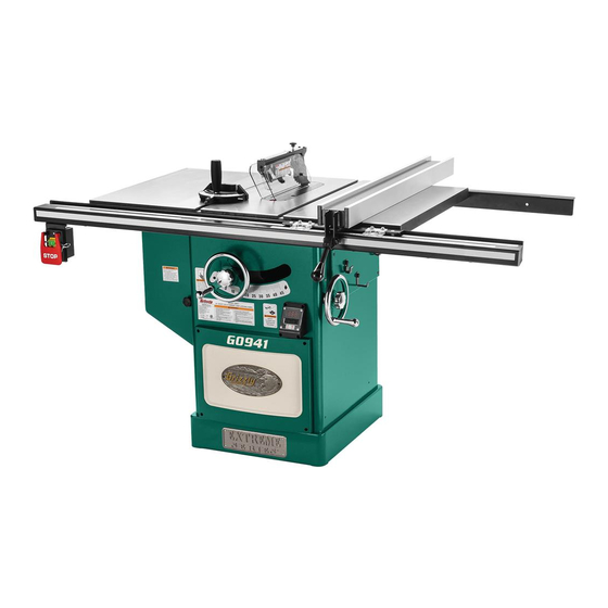
MODEL G0941
10" 3 HP 220V
CABINET TABLE SAW
MANUAL INSERT
The Model G0941 is the same machine as the Model G0651 except it does not have infeed/outfeed tables
and it has different wiring, capacitors, and blade guard. Except for the differences noted in this insert, all
other content in the Model G0651/G0652 owner's manual applies to this machine.
: To reduce the risk of serious injury, you MUST read and understand this insert—and
the entire Model G0651/G0652 manual—BEFORE assembling, installing, or operating this machine!
If you have any further questions about this manual insert or the differences between the Model G0941 and
the Model G0651, contact our Technical Support at (570) 546-9663 or email techsupport@grizzly.com.
COPYRIGHT © OCTOBER, 2020 BY GRIZZLY INDUSTRIAL, INC.
WARNING: NO PORTION OF THIS MANUAL MAY BE REPRODUCED IN ANY SHAPE
OR FORM WITHOUT THE WRITTEN APPROVAL OF GRIZZLY INDUSTRIAL, INC.
(FOR MODELS MANUFACTURED SINCE 09/20) #CS21356 PRINTED IN TAIWAN
Advertisement
Table of Contents

Related Manuals for Grizzly G0941


Summary of Contents for Grizzly G0941
- Page 1 CABINET TABLE SAW MANUAL INSERT The Model G0941 is the same machine as the Model G0651 except it does not have infeed/outfeed tables and it has different wiring, capacitors, and blade guard. Except for the differences noted in this insert, all other content in the Model G0651/G0652 owner's manual applies to this machine.
- Page 2 MACHINE DATA SHEET Customer Service #: (570) 546-9663 · To Order Call: (800) 523-4777 · Fax #: (800) 438-5901 MODEL G0941 10" 3 HP 220V CABINET TABLE SAW Product Dimensions: Weight................................474 lbs. Width (side-to-side) x Depth (front-to-back) x Height..............75 x 44 x 42-1/2 in.
- Page 3 The information contained herein is deemed accurate as of 1/12/2021 and represents our most recent product specifications. Model G0941 PAGE 2 OF 3 Due to our ongoing improvement efforts, this information may not accurately describe items previously purchased. Model G0941 (Mfd. Since 09/20)
- Page 4 • Open-End Wrenches 8 x 10, 11 x 13, 14 x 17mm ....1 Each • Hex Wrenches 3, 4, 5, 6mm ..... 1 Each • Phillips/Flat Combo Screwdriver ....1 Figure 1. Extension wing. Model G0941 (Mfd. Since 09/20)
- Page 5 Hex Bolts M8-1.25 x 12 (Guide Tube) ..7 Figure 4. Fence components. Fence Rail Box Contents (Figure 5) N. Fence Guide Tube ........1 O. Front Rail 75" ..........1 Rear Rail 62 ⁄ " ........... 1 Figure 5. Fence rail components. Model G0941 (Mfd. Since 09/20)
- Page 6 Shadows, glare, or strobe effects that may distract access restricted location. or impede the operator must be eliminated. Access Door Swing = Power Connection at 90º Dust Port 45" Min. 30" 75" Figure . Minimum working clearances. Model G0941 (Mfd. Since 09/20)
- Page 7 Figure 10. Finger tighten. Rear Rail Front Rail Lock Washers Screw Figure 8. Example of front rail installed. Flat Nuts Lock Washer Washer Flat Head Extension Screw Wing Figure 10. Extension wing attached to rails. Model G0941 (Mfd. Since 09/20)
- Page 8 Note: Riving knife is installed for shipping purposes. Two pins in mounting block insert into matching slots on riving knife, keeping it secured. Figure . Tape location for tilting down. Riving Knife Mounting Lock Block Knob Figure 15. Riving knife installed. Model G0941 (Mfd. Since 09/20)
- Page 9 20. Slide miter gauge into T-slot on left side of blade; or store it on storage brackets near blade angle handwheel. Refer to Page 29 of the G0651/G0652 manual for Dust Collection information then refer to Pages 31–32 to complete machine setup. Model G0941 (Mfd. Since 09/20)
- Page 10 The spreader is a metal plate that prevents the Figure 22. Location of table insert and lock knob newly cut kerf of the workpiece from pinching the (blade removed for clarity). backside of the blade, causing kickback. -10- Model G0941 (Mfd. Since 09/20)
- Page 11 Use your best judgment before removing the pawls, as they are provided for your safety. Straightedge Blade Figure 24. Spreader/riving knife alignment zone. -11- Model G0941 (Mfd. Since 09/20)
- Page 12 Figure 26. Pawl and pawl screw fasteners. Re-install blade guard on spreader, making sure front and back pins on blade guard slide all the way into spreader slots, then tighten top knob to secure guard. -12- Model G0941 (Mfd. Since 09/20)
- Page 13 Technical Support at (570) 546-9663. The photos and diagrams included in this section are best viewed in color. You can view these pages in color at www.grizzly.com. -13- Model G0941 (Mfd. Since 09/20)
- Page 14 Electrical Components Figure 30. Digital readout and angle sensor. Figure 27. Motor junction box. Figure 28. ON/OFF switch. Figure 31. Magnetic switch. Figure 29. Start and run capacitors. -14- Model G0941 (Mfd. Since 09/20)
- Page 15 T1 2 T2 4 T3 6 NO 14 WARNING! SHOCK HAZARD! Disconnect power before working on SDE RA-20 Digital Readout wiring. Angle Sensor Start Capacitor 300MFD 125VAC Capacitor 50uF 250VAC 220V Motor ON/OFF Switch -15- Model G0941 (Mfd. Since 09/20)
- Page 16 PARTS We do our best to stock replacement parts when possible, but we cannot guarantee that all parts shown are available for purchase. Call (800) 523-4777 or visit www.grizzly.com/parts to check for availability. Motor & Arbor 21-3 21-1 21-7 21-4...
- Page 17 SWITCH DISABLING LOCK 3/16" P0941052 LEADSCREW 157-2 P0941157-2 SWITCH DISABLING LOCK KEY P0941053 BUSHING P0941158 SUPPORT R P0941054 GASKET P0941165 CORD FIX PLATE BUY PARTS ONLINE AT GRIZZLY.COM! -17- Model G0941 (Mfd. Since 09/20) Scan QR code to visit our Parts Store.
- Page 18 Cabinet 106 16 83-3 83-4 83-2 83-11 83-1 83-9 83-6 83-5 83-10 83-8 83-7 BUY PARTS ONLINE AT GRIZZLY.COM! -18- Model G0941 (Mfd. Since 09/20) Scan QR code to visit our Parts Store.
- Page 19 FENDER WASHER 5MM P0941091 RUBBER BUMPER P0941164 HEX BOLT M3-5 X 6 P0941092 ALIGNMENT PIN 8 X 54 P0941182 PUSH STICK BUY PARTS ONLINE AT GRIZZLY.COM! -19- Model G0941 (Mfd. Since 09/20) Scan QR code to visit our Parts Store.
- Page 20 PHLP HD SCR M5-.8 X 6 P0941229 PAWL MOUNTING BRACKET P0941214 KNOB BOLT 3-LOBE, M6-1 X 35 P0941230 P0941215 BLADE GUARD BODY P0941231 SHAFT BUY PARTS ONLINE AT GRIZZLY.COM! -20- Model G0941 (Mfd. Since 09/20) Scan QR code to visit our Parts Store.
- Page 21 HEX BOLT M6-1 X 45 P0941311 FENCE HANDLE SHAFT P0941325 LOCK NUT M6-1 P0941312 P0941326 OVAL TAPERED KNOB P0941313 FLAT HD SCR M6-1 X 8 BUY PARTS ONLINE AT GRIZZLY.COM! -21- Model G0941 (Mfd. Since 09/20) Scan QR code to visit our Parts Store.
- Page 22 FLAT HD SCR M6-1 X 8 P0941407 HEX NUT 8-32 P0941416 O-RING 4.8 X 1.9 P5 P0941408 PHLP HD SCR 1/4-20 X 1/2 BUY PARTS ONLINE AT GRIZZLY.COM! -22- Model G0941 (Mfd. Since 09/20) Scan QR code to visit our Parts Store.
- Page 23 HEX NUT M8-1.25 P0941504 FRONT RAIL 75" P0941516 LEFT SCALE 18" P0941509 FLAT WASHER 8MM P0941517 RIGHT SCALE 36" P0941510 LOCK WASHER 8MM BUY PARTS ONLINE AT GRIZZLY.COM! -23- Model G0941 (Mfd. Since 09/20) Scan QR code to visit our Parts Store.
- Page 24 Safety labels help reduce the risk of serious injury caused by machine hazards. If any label comes off or becomes unreadable, the owner of this machine MUST replace it in the original location before resuming operations. For replacements, contact (800) 523-4777 or www.grizzly.com. BUY PARTS ONLINE AT GRIZZLY.COM! -24- Model G0941 (Mfd.
- Page 25 ***IMPORTANT UPDATE*** For Machines Mfd. Since 2/19 and Owner's Manual Revised 09/10 For questions or help with this product contact Tech Support at (570) 546-9663 or techsupport@grizzly.com The following change was recently made since the owner's manual was printed: •...
- Page 26 New Blade Guard Parts 200V3 200V3-2 200V3-1 200V3-5 200V3-3 200V3-4 200V3-6 200V3-7 200V3-14 200V3-32 200V3-20 200V3-13 200V3-15 200V3-8 200V3-16 200V3-6 200V3-17 200V3-7 200V3-7 200V3-3 200V3-8 200V3-11 200V3-5 200V3-13 200V3-12 200V3-4 200V3-9 200V3-10 200V3-3 200V3-3 200V3-7 200V3-8 200V3-23 200V3-5 200V3-24 200V3-21 200V3-25 200V3-22 200V3-26...
- Page 27 ***IMPORTANT UPDATE*** For Machines Mfd. Since 07/17 and Owner's Manual Revised 09/10 For questions or help with this product contact Tech Support at (570) 546-9663 or techsupport@grizzly.com The following changes were recently made since the owner's manual was printed: •...
- Page 28 For Machines Mfd. Since 5/17 and Owner's Manual Revised 9/10 For questions or help with this product contact Tech Support at (570) 546-9663 or techsupport@grizzly.com The following changes were recently made to this machine since the owner's manual was printed: •...
- Page 29 Updated G0651 Wiring Diagram 220V, 1-Ph (Replaces Page 84) 6-15 Plug (Included) Ground 220 VAC L1 1 L2 3 L3 5 NO 13 NC21 Magnetic Switch MA-18 Assembly MPE-18 Installation work and (Figure 150, Page 83) electrical wiring NC22 must be done by qualified electrician in accordance with T1 2...
- Page 30 Updated G0652 Wiring Diagram 220V, 3-Ph (Replaces Page 86) Power Junction Box Ground 3-PHASE 220VAC DISCONNECT SWITCH (as recommended ) PHASE CONVERTER Ground If connecting machine to a phase converter, the manufactured leg must be connected to terminal L3. L1 1 L2 3 L3 5 NO 13...
- Page 31 Updated G0652 Wiring Diagram 440V, 3-Ph (Replaces Page 87) Ground Power Junction Box 3-PHASE 440 VAC DISCONNECT SWITCH (as recommended ) MOTOR DIRECTION Ground If motor rotates in opposite direc- tion, swap any two power source wires at the power junction box. L1 1 L2 3 L3 5...
- Page 32 ***IMPORTANT UPDATE*** for machines mfd. since January, 2010 & owner's manual revised september, 2010 For questions or help with this product contact Tech Support at (570) 546-9663 or techsupport@grizzly.com We recently discovered the following mistake in the owner's manual: •...
- Page 33 g0651 Wiring diagram 220v, 1-ph 6-15 Plug (Included) Ground 220 VAC L1 1 L2 3 L3 5 NO 13 NC15 Magnetic Switch MA-18 Assembly MPE-18 Installation work and electrical wiring NC16 must be done by qualified electrician in accordance with T1 2 T2 4 T3 6...
- Page 34 TABLE SAW W/RIVING KNIFE OWNER'S MANuAL 175370 Copyright © marCh, 2008 By grizzly industrial, inC. revised septemBer, 2010 (Bl) WARNING: NO pORTION OF ThIS MANuAL MAy BE REpRODucED IN ANy ShApE OR FORM WIThOuT ThE WRITTEN AppROVAL OF GRIzzLy INDuSTRIAL, INc.
-
Page 36: Table Of Contents
Crosscut sled..........60 preventing Kickback ........13 SEcTION 6: AFTERMARKET AccESSORIES protecting yourself from Kickback ....13 FROM GRIzzLy ..........61 glossary of terms ........14 SEcTION 7: MAINTENANcE ......65 SEcTION 2: pOWER SuppLy ...... 15 schedule ............65 Correcting phase polarity (g0652) .... -
Page 37: Introduction
manner. -
Page 38: G0651 Machine Data Sheet
MACHINE DATA SHEET Customer Service #: (570) 546-9663 · To Order Call: (800) 523-4777 · Fax #: (800) 438-5901 MODEL G0651 10" HEAVY-DUTY CABINET TABLE SAW WITH RIVING KNIFE Product Dimensions: Weight................................430 lbs. Length/Width/Height......................... 91-1/2 x 75 x 40-5/8 in. Foot Print (Length/Width)........................ - Page 39 Motors: Main Type........................TEFC Capacitor Start Induction Horsepower..............................3 HP Voltage................................220V Phase................................ Single Amps................................13A Speed..............................3450 RPM Cycle................................60 Hz Number Of Speeds............................1 Power Transfer ........................... Belt Drive Bearings......................Sealed & Permanently Lubricated Main Specifications: Blade Information Maximum Blade Diameter.......................... 10 in. Riving Knife/Spreader Thickness....................0.09 in.
- Page 40 Construction Table Construction..........................Cast Iron Wings Construction..........................Cast Iron Cabinet Construction......................Pre-Formed Steel Trunnions Construction........................Cast Iron Base Construction........................Pre-Formed Steel Body Assembly Contruction....................Pre-Formed Steel Fence Assembly Construction..................Aluminum Extruded Body Rails Construction............................Steel Miter Guage Construction................Aluminum Body with Steel Body Guard Construction....................
-
Page 41: G0652 Machine Data Sheet
MACHINE DATA SHEET Customer Service #: (570) 546-9663 · To Order Call: (800) 523-4777 · Fax #: (800) 438-5901 MODEL G0652 10" 5 HP 3-PHASE HEAVY-DUTY CABINET TABLE SAW WITH RIVING KNIFE Product Dimensions: Weight................................430 lbs. Length/Width/Height......................... 91-1/2 x 75 x 40-5/8 in. Foot Print (Length/Width)........................ - Page 42 Motors: Main Type........................TEFC Capacitor Start Induction Horsepower..............................5 HP Voltage.............................. 220V/440V Prewired..............................220V Phase.................................Three Amps................................12/6A 12/6a Speed..............................3450 RPM Cycle................................60 Hz Number Of Speeds............................1 Power Transfer ........................... Belt Drive Bearings......................Sealed & Permanently Lubricated Main Specifications: Blade Information Maximum Blade Diameter.......................... 10 in. Riving Knife/Spreader Thickness....................0.09 in.
- Page 43 Miter Gauge Information Miter Gauge Slot Type..........................T-Slot Miter Gauge Slot Size Width........................3/4 in. Miter Gauge Slot Size Height........................3/8 in. Construction Table Construction....................Precision Ground Cast Iron Wings Construction..........................Cast Iron Cabinet Construction......................Pre-Formed Steel Trunnions Construction........................Cast Iron Base Construction........................Pre-Formed Steel Body Assembly Contruction....................Pre-Formed Steel Fence Assembly Construction..................Aluminum Extruded Body Rails Construction............................Steel...
-
Page 44: Identification
Identification Figure 1. g0651 identification. A. Front rail tube B. Front rail c. miter gauge For your Own Safety Read Instruction D. Blade guard and spreader Manual Before Operating Saw E. outfeed table Fence scale indicator a) Wear eye protection. G. -
Page 45: Section 1: Safety
SEcTION 1: SAFETy For Your Own Safety, Read Instruction Manual Before Operating this Machine The purpose of safety symbols is to attract your attention to possible hazardous conditions. This manual uses a series of symbols and signal words intended to convey the level of impor- tance of the safety messages. - Page 46 DISCONNECTING POWER SUPPLY. FORCING MACHINERY. GUARDS & COVERS. APPROVED OPERATION. NEVER STAND ON MACHINE. STABLE MACHINE. DANGEROUS ENVIRONMENTS. AWKWARD POSITIONS. ONLY USE AS INTENDED. USE RECOMMENDED ACCESSORIES. UNATTENDED OPERATION. CHILDREN & BYSTANDERS. MAINTAIN WITH CARE. REMOVE ADJUSTING TOOLS. CHECK DAMAGED PARTS. SECURING WORKPIECE.
-
Page 47: Additional Safety For Table Saws
Additional Safety for Table Saws HAND POSITIONING. FENCE. PUSH STICKS/BLOCKS. BLADE GUARD. CUT-OFF PIECES. BLADE ADJUSTMENTS. RIVING KNIFE. CHANGING BLADES. KICKBACK. DAMAGED SAW BLADES. FEEDING WORKPIECE. DADO AND RABBET OPERATIONS. CUTTING CORRECT MATERIAL. -12- model g0651/g0652 (mfg. since 1/10) -
Page 48: Preventing Kickback
preventing Kickback Statistics show that most common acci- dents among table saw users can be Take the precautions below to avoid the most linked to kickback. Kickback is typically common causes of kickback: defined as the high-speed expulsion of stock from the table saw toward its opera- •... -
Page 49: Glossary Of Terms
Become familiar with these terms for assembling, adjusting or operating this machine. your safety is VERy important to us at grizzly! ARBOR: a metal shaft extending from the drive... -
Page 50: Section 2: Power Supply
SEcTION 2: pOWER SuppLy circuit Information Availability For your own safety and protection of property, consult a qualified electrician if you are unsure about wiring practices or electrical codes in your area. Electrocution, fire, equipment damage may occur if machine is not Note: The circuit requirements listed in this man- correctly grounded and ual apply to a dedicated circuit—where only one... - Page 51 G0652 circuit Requirements Serious injury could occur if you connect the machine to power before completing the setup process. DO NOT connect to power Nominal Voltage ......220V/240V until instructed later in this manual. cycle ............60 hz phase ............ 3-phase G0651 connection Device circuit Rating ........
- Page 52 Extension cords (G0651 Only) G0652 connection Device Minimum Gauge Size ......12 AWG Maximum Length (Shorter is Better)..50 ft. Figure 3. typical hardwire setup with a locking disconnect switch. Volts Total Length of Cord in Feet Ampere Rating 120V 240V More Than More Than...
-
Page 53: Correcting Phase Polarity (G0652)
(570) source if hardwired. 546-9663. remove the junction box cover (Figure 33... -
Page 54: Section 3: Setup
SEcTION 3: SETup Setup Safety Items Needed for Setup the following items are needed to complete the This machine presents setup process, but are not included with the serious injury hazards machine: to untrained users. Read through this entire manu- Description al to become familiar with •... -
Page 55: Inventory
Inventory Fasteners (and where used): • Flat Washer 8mm (miter gauge) ....1 • hex Bolts m8-1.25 x 12 (Fence Brackets) .. 2 • Flat Washers 8mm (Fence Brackets) ..2 the following is a description of the main compo- •... - Page 56 Extension Table Outfeed Table Box contents: (Figure 9) Box contents: (Figure 10) A. extension table .......... 1 A. outfeed table ..........1 B. lower shelf ..........1 B. lower shelf ..........1 c. shelf end plate ........... 1 c. shelf end plate ........... 1 D.
-
Page 57: Hardware Recognition Chart
hardware Recognition chart -22- model g0651/g0652 (mfg. since 1/10) -
Page 58: Cleanup
cleanup Gasoline and petroleum products have low flash points and can explode or cause fire if used to clean machinery. Avo i d u sing t h e s e p r o du c t s to cl e a n m ac hin e r y. Many cleaning solvents toxic inhaled. -
Page 59: Site Considerations
Site considerations Weight Load Physical Environment Machine Data Sheet Space Allocation Electrical Installation See below for required space allocation. Lighting Children or untrained people may be seriously injured by this machine. Only install in an access restricted location. Figure 12. minimum working clearances. -24- model g0651/g0652 (mfg. -
Page 60: Assembly
Assembly secure the metal plates to the table with m8-1.25 x 25 flat head screws on the right side of the table saw cabinet, as shown in Figure 15, then thread two m8-1.25 x 12 hex To assemble the extension table and outfeed bolts with 8mm flat washers into the metal tables: plates. - Page 61 Fasten the 79" rear rail to the extension table with three m8-1.25 x 25 cap screws, three support leg 8mm lock washers, six 8mm flat washers, and three m8-1.25 hex nuts, as shown in Figure 17. Finger tighten for now. hex nut Foot Figure 19.
- Page 62 11. Fasten the shelf end plate to the legs with 15. repeat Steps 8-11 to install the feet, sup- four m6-1 x 12 phillips head screws and 6mm port legs, and shelf end plate on the outfeed flat washers, as shown in Figure 21. table.
- Page 63 21. Fasten the on/oFF switch to the left end riving Knife of the front rail with two m8-1.25 x 12 hex bolts, 8mm flat washers and 8mm lock wash- mounting ers, then insert the switch disabling lock, as Block shown in Figure 25. lock Knob switch...
-
Page 64: Dust Collection
Dust collection 28. mount the fence on the front rail to the right of the blade. 29. install the fence resting brackets (Figure 30) onto the back of the cabinet with the two m8-1.25 x 12 hex bolts and 8mm flat wash- ers. -
Page 65: Power Connection
power connection Before the machine can be connected to the power source, an electrical circuit must be made available that meets the minimum specifications strain relief given in "Circuit requirements for 220v" on page 15. if a power circuit has not been prepared for the machine, do that now. -
Page 66: Test Run
Test Run insert the switch disabling lock through the green on button, as shown in Figure 35. test run your machine to make sure it runs prop- erly and is ready for regular operation. the test run consists of verifying the following: lock 1) the motor powers up and runs correctly, 2) the safety disabling mechanism on the switch... -
Page 67: Final Setup
Final Setup Recommended Adjustments the remaining tasks required for assembling the saw include the following steps: installing the For your convenience, the adjustments listed table insert and cutting a slot for the blade, check- below have been performed at the factory and no ing fence parallelism, installing the blade guard, further setup is required to operate this machine. -
Page 68: Section 4: Operations
Regardless of the content in this section, Grizzly Industrial will not be held liable for Figure 37. Basic table saw controls. accidents caused by lack of training. Blade Tilt Lock: locks blade tilt angle. -
Page 69: Operation Overview
Operation Overview Disabling & Locking Switch the purpose of this overview is to provide the novice machine operator with a basic understand- ing of how the machine is used during a typical operation, so the controls/components discussed Figure later in this manual are easier to understand. due to the generic nature of this overview, it is not intended to be an instructional guide. -
Page 70: Non-Through & Through Cuts
Non-Through & Stock Inspection Through cuts some workpieces are not safe to cut or may require modification before they are safe to cut. Non-Through cuts Before cutting, inspect all workpieces for the following: Material Type: Figure Foreign Objects: Figure 40. example of a non-through cut. Large/Loose Knots: "... -
Page 71: Blade Requirements
Blade Requirements Crosscut blade features: the spreader/riving knife included with this machine is 0.09" (2.3mm) thick and is only designed for 10" diameter blades. When choosing a main blade, make sure the blade size meets the requirements listed below. the thickness of the blade body and teeth can be measured with calipers or any precision measur- ing device. -
Page 72: Blade Installation
Blade Installation Laminate blade features: To install a new blade: disConneCt saW From poWer! put on heavy leather gloves and raise the arbor all the way up. remove the table insert and blade guard/riv- ing knife, depending on what is installed. use the arbor wrenches to loosen and remove the arbor nut, flange, and blade. -
Page 73: Blade Guard Assembly
Blade Guard Assembly In order to work properly, the spreader cannot be bent or misaligned with the blade. If the spreader gets accidentally bent, take the time to straighten it or just replace it. the term "blade guard" refers to the assembly using a bent or misaligned spreader will that consists of the clear polycarbonate shield, the increase the risk of kickback! - Page 74 lift the blade guard cover just enough to slide — if the spreader/riving knife is not inside the table insert into the table slot over the the alignment zone and not parallel with blade, then secure the insert with the knob on the blade, then it needs to be adjusted.
- Page 75 Re-installing Pawls loosen the knob on top of the spreader, then remove the blade guard. We do not recommend removing the pawls during normal operations unless absolutely slide the pin in the pawl block into the sec- necessary. In most situations, removing the ond groove from the front of the spreader, as pawls will increase your risk of serious per- shown in Figure 54.
-
Page 76: Riving Knife
Riving Knife In order to work properly, the riving knife cannot be bent or misaligned with the the riving knife works in the same manner as blade. If the riving knife gets accidentally the spreader on the blade guard assembly. it is a bent, take the time to straighten it or just metal plate that prevents the newly cut workpiece replace it. -
Page 77: Cutting A Zero Clearance Insert
cutting a zero Clamps clearance Insert a zero clearance insert is provided with the table insert saw to reduce workpiece tear out and increase user safety. the insert can be customized to fit a specific blade height or blade angle for the appli- cable cutting operation. -
Page 78: Ripping
Ripping Note: The jointed edge of the workpiece must slide against the fence during the cut- ting operation. "ripping" means cutting with the grain of a natu- 10. use a push stick to feed the workpiece ral wood workpiece. in man-made materials such through the saw blade, as shown in Figure as mdF or plywood, ripping simply means cutting 59, until the workpiece is completely past the... -
Page 79: Crosscutting
crosscutting Miter cuts "Crosscutting" means cutting across the grain of a miter is an angled crosscut. miters are usually a natural wood workpiece. in other man-made cut in the same manner as crosscuts, using the materials, such as mdF or plywood, crosscutting miter gauge and a predetermined mark on the means cutting across the width of the workpiece. -
Page 80: Blade Tilt/Bevel Cuts
Blade Tilt/Bevel cuts Installing a Dado Blade disConneCt saW From poWer! When the blade tilt stop bolts are properly adjust- remove the table insert, the blade guard ed (page 69), the blade tilt handwheel allows assembly or riving knife, and the saw blade. the operator to tilt the blade to the left, anywhere between 0°... - Page 81 cutting Dadoes with a Dado Blade To cut a dado with a dado blade: Figure adjust the dado blade to the desired depth of cut. adjust the distance between the fence and the inside edge of the blade, as shown in Figure 63, to dado the length of a workpiece.
- Page 82 cutting Dadoes with a Standard reconnect the saw to the power source and turn the saw ON. allow the blade to reach full Blade speed, then perform the cutting operation. a ripping blade (described on page 36) is typically the best blade to use for cutting dadoes when repeat the cutting operation on the other using a standard blade, because it removes saw- side of the dado channel, as shown in Figure...
-
Page 83: Rabbet Cutting
Rabbet cutting Always use push sticks, featherboards, push paddles and other safety accessories Commonly used in furniture joinery, a rabbet is an whenever possible to increase safety and l-shaped groove cut in the edge of the workpiece. control during operations which require rabbets can be cut with either a dado blade or a that the blade guard be removed from the standard saw blade. - Page 84 cutting Rabbets with a Standard Blade a ripping blade is typically the best blade to use for cutting rabbets when using a standard blade because it removes sawdust very efficiently. (see page 36 for blade details.) also, a sacrificial fence is not required when cutting rabbets with a stan- dard blade.
-
Page 85: Resawing
Resawing Making Resaw Barrier the resaw barrier acts in tandem with the rip fence when resawing to provide tall support for the workpiece to minimize the probability of it binding against the blade and causing kickback. Resawing operations require proper pro- Tools Needed: cedures to avoid serious injury. - Page 86 Auxiliary Fence the auxiliary fence is necessary if you are resawing a workpiece that is taller than it is wide. it should be no less than ⁄ " shorter than the board to be resawn. components Needed for the Auxiliary Fence: Wood* ⁄...
- Page 87 attach the auxiliary fence to the standard fence and set it to the desired width. Always use push sticks or push paddles to Note: Account for blade kerf, the rough cut increase safety and control during opera- made by the blade, and the inaccuracy of tions which require that the blade guard the fence scale when the auxiliary fence is and spreader must be removed from the...
-
Page 88: Section 5: Shop Made Safety Accessories
SEcTION 5: ShOp MADE SAFETy AccESSORIES Featherboards We recommend using a bandsaw for making fingers in the next step because it tends to easily made from scrap stock, featherboards be safer. A table saw can be used, but it will provide an added degree of protection against over-cut the underside of the ends, produce kickback, especially when used together with... - Page 89 rout a ⁄ "– ⁄ " wide slot 4"–5" long in the drill a ⁄ " hole in the center of the bar, then workpiece and 1"–2" from the short end of the countersink the bottom to fit a ⁄ "-20 flat head featherboard (see Figure 77).
- Page 90 Mounting Featherboards with Mounting Featherboard in Miter Slot clamps lower the saw blade, then adjust the fence to lower the saw blade, then adjust the fence to the desired width and secure it. the desired width and secure it. place the workpiece evenly against the fence, place the workpiece against the fence, mak- making sure it is 1"...
-
Page 91: Push Sticks
push Sticks Supporting: a second push stick can be used to keep the workpiece firmly against the fence while cutting. When using a push stick in this manner, only apply pressure before the blade; otherwise, When used correctly, push sticks reduce the risk pushing the workpiece against or behind the of injury by keeping hands away from the blade blade will increase the risk of kickback (see "push... -
Page 92: Push Blocks
push Blocks the notched end of the push block is then used to push the workpiece the rest of the way through the cut, keeping the operator's hands at a safe distance from the blade. a push stick is often When used correctly, a push block reduces the used at the same time in the other hand to sup- risk of injury by keeping hands away from the... -
Page 93: Narrow-Rip Auxiliary Fence & Push Block
Narrow-Rip Auxiliary Note: We recommend cutting the hardwood board oversize, then jointing and planing it Fence & push Block to the correct size to make sure the board is square and flat. Only use furniture grade plywood or kiln dried hardwood to prevent warping. - Page 94 using Auxiliary Fence & push Block place the workpiece 1" behind the blade and evenly against the table and the auxiliary place the auxiliary fence on the table and fence. clamp it to the fence at both ends, then adjust the distance between the auxiliary fence and the blade—this determines how wide the workpiece will be ripped (see Figure 91).
-
Page 95: Outfeed & Support Tables
Outfeed & Support crosscut Sled Tables a crosscut sled (see Figure 95) is a fantastic way to improve the safety and accuracy of cross- one of the best accessories for improving the cutting on the table saw. most expert table saw safety and ease of using a table saw is simply plac- operators use a crosscut sled when they have ing a large table (outfeed table) behind the saw to... -
Page 96: Section 6: Aftermarket Accessories From Grizzly
Grizzly. NOTICE Refer to the newest copy of the Grizzly catalog for other accessories available for this machine. h8085—Front Tool Box for G0651/G0652 this heavy-duty tool box features powder coated Figure 97. - Page 97 G3445—precision Saw Tool T10222—Router Table Attachment this high impact plastic saw aid™ quickly mea- T10223—Sliding Table Attachment sures blade height and angle and can also serve accessorize your table saw with either of these as a solid push stick. includes a graduated ruler attachments for ultimate functionality.
- Page 98 T20501—Face Shield crown protector 4" h1049—clear Flexible hose 2 ⁄ " x 10' T20502—Face Shield crown protector 7" h1052—clear Flexible hose 4" x 10' T20503—Face Shield Window G3123—Black Flexible hose 2 ⁄ " x 10' G1536—Black Flexible hose 4" x 10' T20452—"Kirova"...
- Page 99 G0638—10hp 3-ph cyclone Dust collector G7581—Superbar™ our largest dust Collector features a whopping G7582—Master plate 4029 CFm capacity and can handle any large the miter slot mounted superbar™ will align, tune duct system with a static pressure loss less than and calibrate your tablesaw to within ±.001 in just 16.8”...
-
Page 100: Section 7: Maintenance
SEcTION 7: MAINTENANcE cleaning Always disconnect power to the machine before Cleaning the model g0651/g0652 is relatively performing maintenance. easy. vacuum excess wood chips and sawdust, Failure to do this may and wipe off the remaining dust with a dry cloth. result in serious person- if any resin has built up, use a resin dissolving al injury. -
Page 101: Lubrication
Lubrication Worm Gear, Bevel Gears, Mounting plate Teeth Check every month. use a wire brush and mineral spirits to clean away any built up grime and debris it is essential to clean components before lubri- from the worm gear, bevel gear, and mounting cating them because dust and chips build up on plate teeth (Figure 111). -
Page 102: Section 8: Service
SEcTION 8: SERVIcE review the troubleshooting and procedures in this section to fix or adjust your machine if a problem devel- ops. if you need replacement parts or you are unsure of your repair skills, then feel free to call our technical support at (570) 546-9663. - Page 103 symptom possible Cause possible solution handwheel binds or 1. lock knob is engaged. 1. loosen lock knob. is difficult to move. 2. handwheel shaft pins are wedged. 2. remove handwheel and adjust shaft pins. 3. handwheel is inserted too far. 3.
-
Page 104: Blade Tilt Stops
Blade Tilt Stops adjust the indicator position by loosening the phillips head screw, moving the indica- tor, then tightening the screw and reinstall- ing the handwheel. proceed to Setting 45º the table saw features stop bolts that stop the Stop Bolt on page 70. blade exactly at 45°... - Page 105 —if the blade is 45° to the table, then adjust- ments do not need to be made. —if the blade is not 45° to the table, you will need to adjust the 45° stop screw. proceed to the next step. tilt the blade to 20°, so there is room for the stop bolt to move.
-
Page 106: Miter Slot To Blade
Miter Slot to Blade rotate the marked blade tip to the other end of the table insert. parallelism Compare the distance from the marked blade tip to the miter slot, as shown in Figure 120. Tools Needed adjustable square ..........1 metal shim stock ...... -
Page 107: Blade Alignment
tilt the blade to 45° and repeat Steps 3-6. 11. tighten one bolt a small amount and then move on to each of the others, tightening —if the blade is still parallel with the miter each down the same amount. Continue to slot, continue onto the Blade Alignment rotate through the bolts, tightening them a procedure. -
Page 108: Spreader Or Riving Knife Alignment
Spreader or Riving Knife Alignment checking Alignment the blade guard spreader and riving knife must be aligned with the blade when installed. if the spreader/riving knife is not aligned with the blade, then the workpiece will before forced sideways during the cut, which will increase the risk of kick- Figure 125. - Page 109 Adjusting Alignment tighten the lock knob (see Figure 127), then re-install the table insert. the spreader/riving knife mounts to a block that can be repositioned to correctly align the spread- er/riving knife to the blade. the mounting block lock Knob adjusts by turning the set screws in each corner of the block.
-
Page 110: Fence Adjustments
Fence Adjustments adjust the set screws (Figure 129) on top of the fence bracket to ensure the fence face is 90° to the table. there are four main adjustments for the fence: square, height, parallelism, and clamping pres- sure. Keep in mind that these adjustments are interconnected and some trial-and-error may be needed to achieve satisfactory results. - Page 111 Note: If the front end of the fence needs to — if the fence/miter slot are parallel with the blade, as shown in Figure 131, no further be adjusted up or down, use the set screws from Figure 129; however, turn them in adjustments need to be made.
-
Page 112: Fence Scale Calibration
Fence Scale rotate the blade 180° and recheck the dis- tance between the fence and the blade tooth calibration you marked in Step 4 to ensure they are par- allel (see Figure 131 on page 76). use trial-and-error to adjust the set screws the fence scale indicator windows, shown in so the fence is parallel with the blade and the Figure 134, can be calibrated with the fence... -
Page 113: Miter Gauge Adjustments
Miter Gauge place the 90° square evenly against the face of the miter gauge and the blade, as shown Adjustments in Figure 136. — if the square touches the miter body and the body of the blade (not the teeth) evenly the miter gauge is equipped with stop screws that at the same time, then it is square to the allow you to easily adjust the miter gauge from 45°... -
Page 114: Digital Readout Calibration
Table Tilt handwheel tighten the jam nut and the cap screws, rein- stall the angle sensor cover, then close the Backlash motor access cover. Digital Readout the table tilt handwheel should move with very calibration little backlash or slop when the saw is new. over time the tilt gears may wear, increasing backlash. -
Page 115: Belt Tension & Replacement
Belt Tension & Replacement Wood Block the belt stretches slightly as the saw is used. most of the belt stretching will happen during the first 16 hours of use, but it may continue in small increments through continued use. to ensure optimum power transmission from the motor to the blade, the belt must be in good condition. - Page 116 Replacing Belt Belt disConneCt saW From poWer! raise the motor all the way up, tilt it to 0°, and open the motor cover. loosen the three motor mounting hex nuts (Figure 140) two turns, and place the 4x4 block between the cabinet and bottom of the motor, as shown in Figure 143.
-
Page 117: Section 9: Wiring
WIRE/COMPONENT DAMAGE. MOTOR WIRING. MODIFICATIONS. CAPACITORS/INVERTERS. WIRE CONNECTIONS. CIRCUIT REQUIREMENTS. EXPERIENCING DIFFICULTIES. The photos and diagrams included in this section are best viewed in color. You can view these pages in color at www.grizzly.com. -82- model g0651/g0652 (mfg. since 1/10) -
Page 118: G0651/G0652 Electrical Components
G0651/G0652 Electrical components Figure 147. g0651 motor junction box. Figure 149. g0651/g0652 digital readout and angle sensor. Figure 148. g0651/g0652 switch. Figure 150. g0651 magnetic switch. READ ELECTRICAL SAFETY -83- model g0651/g0652 (mfg. since 1/10) ON PAGE 82! -
Page 119: G0651 Wiring Diagram 220V, 1-Ph
G0651 Wiring Diagram 220V, 1-ph 6-15 Plug (Included) Ground 220 VAC Magnetic Switch Assembly MPE-18 Installation work and see Figure 150, page 83 electrical wiring must be done by qualified electrician in accordance with all applicable codes and standards. Digital Readout see Figure 150, page 83 Angle Sensor see Figure 149,... -
Page 120: G0652 Electrical Components
G0652 Electrical components Figure 152. g0652 magnetic switch prewired to Figure 154. g0652 magnetic switch converted to 220v, 3-phase. 440v, 3-phase. Note: The thermal relay in Figure 152 is set for 12 Note: The therrmal relay in Figure 154 is adjusted amp, 220V, 3-phase operation. -
Page 121: G0652 Wiring Diagram 220V, 3-Ph
G0652 Wiring Diagram 220V, 3-ph Power Junction Box 3-PHASE 220VAC DISCONNECT SWITCH (as recommended ) PHASE CONVERTER If connecting machine to a phase converter, the manufactured leg must be connected to terminal L3. Installation work and electrical wiring must be done by qualified electrician in Magnetic accordance with all applicable codes and standards. -
Page 122: G0652 Wiring Diagram 440V, 3-Ph
G0652 Wiring Diagram 440V, 3-ph Power Junction Box 3-PHASE 440 VAC DISCONNECT SWITCH (as recommended ) MOTOR DIRECTION If motor rotates in opposite direc- tion, swap any two power source wires at the power junction box. Installation work and electrical wiring must be done by qualified electrician in Magnetic accordance with all applicable codes... -
Page 123: Section 10: Parts
SEcTION 10: pARTS Motor and Arbor Breakdown -88- model g0651/g0652 (mfg. since 1/10) - Page 124 Motor and Arbor Parts List PART # DESCRIPTION PART # DESCRIPTION PLW04M LOCK WASHER 8MM P0651058 LEFT BEVEL GEAR PSB40M CAP SCREW M8-1.25 X 35 PW04M FLAT WASHER 10MM PB06M HEX BOLT M8-1.25 X 12 PLN10M LOCK NUT M10-1.25 16-1 PW01M FLAT WASHER 8MM P0651061...
- Page 125 Motor and Arbor parts List continued G0651 3HP, 220V, SINGLE-PHASE MOTOR G0652 35P, 220V/440V, THREE-PHASE MOTOR P0651021 MOTOR 3HP, 1 PHASE P0652021 MOTOR 5HP, 3 PHASE 21-1 P0651021-1 MOTOR FAN COVER 21-1 P0652021-1 MOTOR FAN COVER 21-2 P0651021-2 MOTOR FAN 21-2 P0652021-2 MOTOR FAN...
-
Page 126: Cabinet Breakdown
cabinet Breakdown -91- model g0651/g0652 (mfg. since 1/10) - Page 127 cabinet parts List PART # DESCRIPTION PART # DESCRIPTION P0651005 EXTENSION WING P0651090 LOCK KNOB M6-1 X 20 PB07M HEX BOLT M8-1.25 X 25 P0651091 RUBBER BUMPER PLW04M LOCK WASHER 8MM P0651092 ALIGNMENT PIN 8 X 54 P0651009V2 TABLE INSERT ASSY V2.01.10 P0651093 MOTOR ACCESS COVER 9V2-1...
-
Page 128: Blade Guard Breakdown
Blade Guard Breakdown PART # DESCRIPTION PART # DESCRIPTION 200V2 P0661002V2 BLADE GUARD ASSY V2.01.10 200V2-15 P0661002V2-15 PUSH NUT 4MM V2.01.10 200V2-1 P0661002V2-1 LEFT PLATE V2.01.10 200V2-16 P0661002V2-16 LEFT PAWL V2.01.10 200V2-2 PLN02M LOCK NUT M5-.8 200V2-17 P0661002V2-17 RIGHT TORSN SPRING V2.01.10 200V2-3 PFH01M FLAT HD SCR M5-.8 X 15... -
Page 129: Fence Assembly Breakdown
Fence Assembly Breakdown REF PART # DESCRIPTION REF PART # DESCRIPTION P0651300 FENCE ASSEMBLY PLN05M LOCK NUT M10-1.5 PS14M PHLP HD SCR M6-1 X 12 P0651315 PLASTIC PAD PW03M FLAT WASHER 6MM P0651316 CLAMPING BRACKET P0651303 INDICATOR PLATE PSS20M SET SCREW M8-1.25 X 8 P0651304 PLASTIC SET SCREW M12-1.75 X 13 P0651318... -
Page 130: Miter Gauge Breakdown
Miter Gauge Breakdown REF PART # DESCRIPTION REF PART # DESCRIPTION P0651400 MITER GAUGE ASSEMBLY P0651409 SPECIAL SET SCREW M5-.8 X 12 PS06 PHLP HD SCR 10-24 X 3/8 P0651410 MITER GAUGE HANDLE P0651402 POINTER PW01M FLAT WASHER 8MM P0651403 BLOCK P0651412 MITER GAUGE... -
Page 131: Extension Table Breakdown
Extension Table Breakdown REF PART # DESCRIPTION REF PART # DESCRIPTION P0651500 EXTENSION TABLE ASSEMBLY PHTEK8M TAP SCREW M4 X 20 P0651501 LEFT SCALE 18" P0651516 RIGHT EXTENSION BRACKET P0651502 RIGHT SCALE 52" P0651517 FENCE TUBE (91-1/2" LONG) P0651503 EXTENSION TABLE PLATE P0651518 FRONT RAIL (91-1/2"... -
Page 132: Outfeed Table Breakdown
Outfeed Table Breakdown REF PART # DESCRIPTION REF PART # DESCRIPTION P0651600 OUTFEED TABLE ASSEMBLY PN03M HEX NUT M8-1.25 P0651601 OUTFEED TABLE PLATE P0651610 FRONT OUTFEED TABLE BRACKET PS14M PHLP HD SCR M6-1 X 12 P0651611 SHELF END PLATE PW03M FLAT WASHER 6MM P0651612 LOWER SHELF BRACKET... -
Page 133: Label Placement
MuST maintain the original location and readability of the labels on the machine. If any label is removed or becomes unreadable, REpLAcE that label before using the machine again. contact Grizzly at (800) 523-4777 or www.grizzly.com to order new labels. -98-... - Page 134 WARRANTY CARD The following information is given on a voluntary basis. It will be used for marketing purposes to help us develop better products and services. Of course, all information is strictly confidential. Note: We never use names more than 3 times. _____________________________________________________________________ _________________________________________________________________________________ _________________________________________________________________________________...
-
Page 136: Warranty And Returns
WARRANTy AND RETuRNS... - Page 137 Buy Direct and Save with Grizzly – Trusted, Proven and a Great Value! ® ~Since 1983~ Visit Our Website Today For Current Specials! ORDER 24 HOURS A DAY! 1-800-523-4777...