Advertisement
SELF CLEANING
ALKALINE FILTER
WIRING DIAGRAMS ..............................................................1
WIRE CONNECTION DIAGRAM ...........................................2
WATER FLOW & REFRIGERATION DIAGRAMS..................3
OPERATION GUIDE ..............................................................4
PRECAUTIONS ......................................................................6
ASSEMBLY DRAWING ..........................................................7
EXPLODE DRAWINGS ..........................................................8
SANITIZING AND CLEANING, SPECIFICATION ..................9
TROUBLE SHOOTING ...........................................................11
HOW TO CHANGE PARTS ....................................................12
Parts marked with "
replace these parts with specified ones for maintaining the safety and performance of the set.
SHARP CORPORATION
SERVICE MANUAL
In the interests of user-safety (Required by safety regulations
in some countries) the set should be restored to its original
condition and only parts identical to those specified should
be used.
CONTENTS
" are important for maintaining the safety of the set. Be sure to
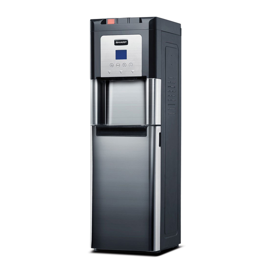
HOT & COLD HIDDEN BOTTLE
WATER COOLER
MODEL:
SWD-78EHL-SL
This document has been published to be used for
after sales service only.
The contents are subject to change without notice.
Advertisement
Table of Contents

Related Manuals for Sharp SWD-78EHL-SL


Summary of Contents for Sharp SWD-78EHL-SL
-
Page 1: Table Of Contents
HOT & COLD HIDDEN BOTTLE SELF CLEANING ALKALINE FILTER WATER COOLER MODEL: SWD-78EHL-SL In the interests of user-safety (Required by safety regulations in some countries) the set should be restored to its original condition and only parts identical to those specified should be used. -
Page 2: Wiring Diagrams
Wiring diagrams page 1 1. Wiring diagram Wiring diagram for BL with LCD display Electrical Wiring Diagram of SWD-78EHL-SL... -
Page 3: Wire Connection Diagram
Wire connection diagram page 2 2. Wire connection diagram Wire connection diagram for BL with LCD display Wire connection diagram for BL cold & hot, Touch panel LCD display(with fuse, with Ozonator, no Switches) Cold water sensor Drawing Number Item Description Color Length (mm) -
Page 4: Water Flow & Refrigeration Diagrams
Water flow and Refrigeration diagrams page 3 3. Water flow diagram water level sensing electrodes 4. Refrigeration diagram water flow sensing electrodes Mechanical valve with switch Hot air return Ozonator Optional Baffle plate Cold water Reservior Cold tap Cook tap Optional Hot tap Hot water... -
Page 5: Operation Guide
Operation guide page 4 5. Operation guide CAUTION This dispenser is intended for water dispensing only. Do NOT use other liquids. Do NOT use for other purposes. Warranty is void if used for any other liquids including coffee, tea, juices, beer or wine. - Page 6 Operation guide page 5 Initial Rinsing of Water Lines This unit has been tested and sanitized prior to packing and shipping. During transit dust and odors can accumulate in the tank and lines. fill with water.wait for 30 minutes,Dispense classes of hot water and 6 glasses of cold water. Dispense Cold Water Note: After setup, it will take 2 hour to get water to maximum cold temperature.
-
Page 7: Precautions
Operation guide page 6 • Place fresh bottle in front of tray. • Clean fresh bottle with a soft cloth and warm soapy water then wepe with clean wet colth. • Remove entire plastic cap from top of bottle. • Insert probe into bottle. •... -
Page 8: Assembly Drawing
Assembly drawing page 7 Back Heating Cooling ON/OFF ON/OFF Control: Hot Water LED Nightlights Pump Hot Water Release Drip Tray Power Cord Control: Cold Water Door Carry Handle Control: Cool Water Bottle Tray Drain Plug Tap: Hot Water Sensor Switch LCD display Tap: Cool Water Filter... -
Page 9: Explode Drawings
Explode drawings page 8 8. Explode drawing(s) NO. appellation BL with stainless panel, with LCD display 6M00001D5V0 4EXGIWV The part of ozone 10200021XX00 (aluminium wired) 10500010NX00 telescopic off set to pump all water out Probe 6WA090BX1W Cold NTC sensor 6M00002D6X DIV001P075 Door switch PB001A552-V04... -
Page 10: Sanitizing And Cleaning, Specification
Sanitizing &cleaning, Specifications page 9 9. Sanitizing and cleaning instructions 9.1: Ozone sterilizing Ozonator works for 12 seconds every 4 hours. 9.2:Cleaning (1) Unplug the power, remove drain cap and silicon plug, drain out the water from back, then plug back the drain seal and cap. - Page 11 page 10 Specifications Model SWD-78EHL-BD Pump motor Motor voltage DC12V Compressor Model QD25HG QPS2-A15MG1 Starter Protector BB45-125 12J-1 Refrigerant R134A Construction Top cover ABS - Black Front Top panel ABS - Black Front Middle panel Stainless Steel Front Middle Insert panel Stainless Steel +IMD Front Bottom panel or Door Stainless Steel...
-
Page 12: Trouble Shooting
Trouble shooting page 11 11. Trouble shooting Problems Reasons How to solve Notice 1. Switch doesn’t work (Or switched off on LCD panel) 1. Check switch (Turn on by touching LCD key) 2. Fuse(s) burnt 2. Check fuse(s) Hot water is not hot 3. -
Page 13: How To Change Parts
How to change parts page 16 How to change parts CAUTION: UNPLUG POWER BEFOREDOING SERVICE 1. Change fuse 1.1 Screw out the fuse cap 1.2 Take out the fuse 1.3 Change a new one and screw on the cap. 2. Change power switch(es) 2.1 Take off the control box cover by unscrewing 2 bolts 2.2 Pull off the wires to Switch(es) NOTE: The lock on the female terminal need to be pressed down before pull out the wire connector. - Page 14 How to change parts page 17 3.11 Plug on wire and check if it works 3.12 Install the control box cover back 4. Change transformer NOTE: Make sure the static protection is equipped before doing service to protect control board. 4.1 Take off the control box cover by unscrewing 2 bolts 4.2 Take off the Control board from the plastic standoffs, then take off 2 wires by using iron.
- Page 15 How to change parts page 18 6. Change the control board with LCD in the IMD NOTE: Make sure the static protection is equipped before doing service to protect control board. 6.1 Take off the IMD panel by pressing the hooks at the bottom. 6.2 Unplug all the wires by pressing down the locks.
- Page 16 How to change parts page 19 9. Change drain seal and cap 9.1 Open the door to Stop pumping water 9.2 Unscrew on bolt then take out the drain cap 9.3 Pull out the seal. CAUTION: Water may be hot! 9.4 Change new seal and cap.
- Page 17 How to change parts page 20 11.2 Disconnect the wire connector by pressing the lock at the back. 11.3 Change a new pump into the housing. 11.4 Connect the wires and then plug in power, drain a few cups water from the taps, then press down the door switch to see if it is works.
- Page 18 How to change parts page 21 14.2 Remove the door hinge plate by unscrewing 3 bolts, remove the door rope then remove the door. 14.3 Unscrew the bolts for middle panel from the front and back, then take off the middle panel. 14.4 Take off the top front panel by unscrewing 2 bolts.
- Page 19 How to change parts page 22 vpanel. 16.5 Install the LED light assembly to the new front panel assembly. 16.6 Insert the hooks of the new top front panel assembly into the holes on the side panel, then screw on the bolts on the top. 16.7 Connect the tap pusher and tap stick in place.
- Page 20 How to change parts page 23 equipments, then plug all the wire connectors. 19.4 Insert 2 hooks of the insert panel/IMD panel to the Top front panel on the top first, then press down, the lower hooks will be clicked in at the bottom. 20.
- Page 21 How to change parts page 24 22.2 Pull off the wire connector from the driver board. 22.3 Open the top cover. 22.4. Pull off the silicone tube on the ozonator. 22.5 Unscew 2 bolts for the ozonator and change a new one. 22.6 Connect the silicone tube and wire back.