Advertisement
SHARP SERVICE MANUAL
PARTS IDENTIFICATION AND SPECIFIC INFORMATION ...................................................
CAUTIONS FOR USE .............................................................................................................
IMPORTANT SAFETY INSTRUCTIONS ................................................................................
WIRING DIAGRAM AND CIRCUIT DIAGRAM .......................................................................
COOLING SYSTEM DIAGRAM AND HOT SYSTEM DIAGRAM ...........................................
COMPONENT REPLACEMENT PROCEDURE .....................................................................
TROUBLESHOOTING ............................................................................................................
SERVICE PARTS LIST ...........................................................................................................
HOT & COLD WATER DISPENSER
In the interests of user-safety (Required by safety
regulations in some countries) the set should be restore
to its original condition and only parts identical to those
specified should be used.
TABLE OF CONTENTS
SHARP CORPORATION
MODEL
SB-29
SB-29S
Page
2
3
3
4
5
6 - 13
14
15 - 19
Advertisement

Related Manuals for Sharp SB-29S


Summary of Contents for Sharp SB-29S
-
Page 1: Table Of Contents
SHARP SERVICE MANUAL HOT & COLD WATER DISPENSER MODEL SB-29 SB-29S In the interests of user-safety (Required by safety regulations in some countries) the set should be restore to its original condition and only parts identical to those specified should be used. -
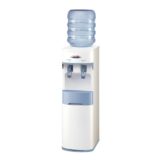
Page 2: Parts Identification And Specific Information
Lamp indicator (Cool) Push button Faucet ass’y (Cool water) Faucet ass’y (Hot water) Panel-B Drain tray support Drain tray Stand Model : SB-29S Panel-A Stand Model : SB-29 SPECIFIC INFORMATION SB-29 SB-29S Model Rated voltage (V) Rated frequency (Hz) Power consumption... -
Page 3: Cautions For Use
240 cm. in length. (Embed into the ground) 5. If the appliance is malfunction. Do not try to repair this appliance. For your own safety and using this appliance with high efficiency, contact the nearest SHARP service facility for repair. -
Page 4: Wiring Diagram And Circuit Diagram
WIRING DIAGRAM CIRCUIT DIAGRAM... -
Page 5: Cooling System Diagram And Hot System Diagram
COOLING SYSTEM DIAGRAM Tank cooler Cooling coil Condenser ass’y Capillary tube Compressor Filter driers HOT WATER SYSTEM DIAGRAM Silicone tube Tank cooler Space tank Silicone tube Hot water inlet tube Connector pipe Heater tank ass’y Hot water outlet tube Heater set ass’y Drain tube... -
Page 6: Component Replacement Procedure
COMPONENT REPLACEMENT PROCEDURE Before beginning the service inspection and/or repair you will need to disconnect the power cord from the Hot & Cold water dispenser and remove the bottle from the reservoir. REMOVE OF PTC RELAY 1. Remove the insulating seal cork tape from terminal cover. 2. - Page 7 REMOVE OF POWER CORD ASS’Y 1. Remove the terminal cover. 2. Remove the screw holding the power cord ass’y 3. Remove 2 closed terminal to power cord ass’y. 4. Now the power cord ass’y is free. Screw Closed terminal Compressor Power cord ass’y Thermo motor Cover strap...
- Page 8 REMOVE OF PANEL B-A AND FAUCET ASS’Y 1. Remove the drain tray ass’y from the panel-B. 2. Remove 2 screws holding the top plate. 3. Separate out the top plate from the unit. 4. Remove 4 screws holding the faucet cover and detach the faucet cover. 5.
- Page 9 REMOVE OF TEMP. FUSE ASS’Y 1. Disconnect 2 lead wires Temp. fuse ass’y and cut lead wire from the PCB Hot display. 2. Disconnect 2 terminals from thermostat and switch ON/OFF. 2. Remove the screw holding the temp. fuse ass’y to the temp. fuse angle. 3.
- Page 10 REMOVE OF FAUCET CONNECTOR AND TANK CONNECTOR 1. Remove the water partition from the tank cooler ass’y. 2. Remove the panel B-A and faucet ass’y in accordance with “REMOVE OF PANEL B-A AND FAUCET ASS’Y”. 3. Remove the side plate L-R in accordance with “REMOVE OF SIDE PLATE L-R”. 4.
- Page 11 REMOVE OF SIDE PLATE L-R 1. Remove the panel B-A and faucet ass’y in accordance with “REMOVE OF PANEL B-A”. 2. Put the jig into rear of the unit. 3. Remove 2 screws holding the switch ON/OFF ass’y. 4. Remove 4 screws holding the condenser ass’y and remove 6 screws from the side plate L-R to the tank support.
- Page 12 REMOVE OF HEATER TANK ASS’Y 1. Remove the panel B-A and faucet ass’y in accordance with “REMOVE OF PANEL B-A AND FAUCET ASS’Y”. 2. Remove the thermostat in accordance with “REMOVE OF THERMOSTAT”. 3. Remove the heater set ass’y. 4. Cut 3 cord bands and remove the clamp for silicone tube. 5.
- Page 13 REMOVE OF FILTER DRIERS 1. Remove the side plate L-R in accordance with “REMOVE OF SIDE PLATE L-R”. 2. Cut the charge tube and let compressor’s coolant out off the compressor about 1 minute. 3. Blow gas 2 joints, and remove the filter driers from the condenser ass’y and the capillary tube. 4.
-
Page 14: Troubleshooting
TROUBLESHOOTING Problem Possible Cause Corrective Action No cold water and compressor not 1. No voltage received by water 1. Plugged into the outlet. running. dispenser. 2. Faulty wires. 2. Repaired or replaced power cord ass’y. 3. Faulty starting relay. 3. Replaced starting relay. 4. -
Page 15: Service Parts List
PARTS CODE REF. NO DESCRIPTION Q’TY PRICE (FEC) PRINTING & PACKAGING MATERIAL 31B101 INSTRUCTION BOOK 31B102 CARTON BOX 31B103 SHARP BADGE 31B104 NAME PLATE 31A1051 POP WATER DISPENSER 31B107 BOTTLE STICKER 31A108 WARNING STICKER 31B109 HOT WATER STICKER 31B118 INSTRUCTION STICKER... - Page 16 PARTS CODE REF. NO DESCRIPTION Q’TY PRICE (FEC) MECHANICAL PARTS 2-30-1 31B209 FAUCET BODY 2-30-2 31B506 RUBBER VALVE 2-30-3 31B213 PIN VALVE 2-30-4 31B313 SPRING VALVE 2-30-5 31B211 CAP VALVE 2-30-6 31B208 LEVER FAUCET 2-30-7 31B516 O-RING (ID) 10.8*2.4 mm. 2-30-8 31B210 FAUCET MOUNTING PLATE...
- Page 17 SB-29S PARTS CODE REF. NO DESCRIPTION Q’TY PRICE (FEC) PRINTING & PACKAGING MATERIAL 31B101 INSTRUCTION BOOK 31F102 CARTON BOX 31F103 SHARP BADGE 31F104 NAME PLATE 31A1051 POP WATER DISPENSER 31B107 BOTTLE STICKER 31A108 WARNING STICKER 31B109 HOT WATER STICKER 31B118...
- Page 18 PARTS CODE REF. NO DESCRIPTION Q’TY PRICE (FEC) MECHANICAL PARTS 2-25 31B204A PANEL-A 2-26 31B214 PANEL SWITCH 2-27 31B205 FAUCET COVER 2-28 31B206 DRAIN TRAY SUPPORT 2-29 31B207 DRAIN TRAY 2-30 31B208CSET COOL FAUCET SET 2-30-1 31B209 FAUCET BODY 2-30-2 31B506 RUBBER VALVE 2-30-3...