Table of Contents
Advertisement
Quick Links
Advertisement
Table of Contents

Related Manuals for Sharp SW-180NC


Summary of Contents for Sharp SW-180NC
- Page 1 SW-180NC Instruction Manual Version 1 20180619...
- Page 3 Safety rules Make sure your work area is cleared of uninvited people and obstacles every time before you start operating the machine. Never step or stand on the roller table. Your foot may slip or trip on the rollers and you will fall.
- Page 4 Safety rules Never adjust the wire brush or remove chips while the saw blade is still running. It is extremely dangerous if hands or clothing are caught by the running blade. Stop the saw blade before you clean the machine. It is dangerous if hands or clothing are caught by the running blade.
-
Page 5: Table Of Contents
Table of Contents Safety Information Section 1 – Safety Instructions ……………………………………………………………………………………………………… 1-1 Safeguard Devices ………………………………………………………………………………………………………. 1-3 Emergency Stop …………………………………………………………………………………………………………. 1-5 Illustration: Emergency Stop ……………………………………………………………………………………… Safety Labels ………………………………………………………………………………………………………………. 1-6 Illustration: Safety Labels ………………………………………………………………………………………..… Hearing Protection ……………………………………………………………………………………………………… 1-8 CE Compliance ……………………………………………………………………………………………………………. 1-8 Risk Assessment …………………………………………………………………………………………………………. - Page 6 Table of Contents Control Buttons ……………………………………………………………………………………….…….. 4-5 Blade Descend Pressure & Speed Control Panel ………..…………..………………….…… 4-7 HMI Touch Screen & Functions …………………………………………………………….………… 4-7 HMI Error Codes ………………………..……………………………………………………….…………. 4-17 Standard Accessories ………….………………………..……………………………………………….…………… 4-18 Optional Accessories …….…….………………………..…………………………………………….……………… 4-20 Unrolling & Installing the Blade …………………………………………………………………….……………. 4-24 Adjusting Wire Brush ………..……………………………………………………………………….……………….
- Page 7 Table of Contents Every 6 Months ……………….………………………………………………….…………………………. 8-3 Storage Conditions …………………………..………..…………………………………………………………….. 8-3 Terminating the Use of Machine ……..…………..…………………………………………………………….. 8-3 Oil Recommendation for Maintenance ………………………………………………………………………. 8-4 Troubleshooting Section 9 – Introduction ……………………….…….…………………..……………………………………………………………. 9-1 Precautions ………………….…………………..……………………………………………………………………..9-2 General Troubles & Solutions ………………………..……………………………………………………………. 9-2 Minor Troubles &...
-
Page 9: Safety Information
Section 1 SAFETY INFORMATION SAFETY INSTRUCTIONS SAFEGUARD DEVICES EMERGENCY STOP SAFETY LABELS HEARING PROTECTION CE COMPLIANCE RISK ASSESSMENT Safety is a combination of a well-designed machine, operator’s knowledge about the machine and alertness at all times. This band machine has incorporated many safety measures during the design process and used protective devices to prevent personal injuries and potential risks. - Page 10 When a workpiece is too long or heavy, Use a sharp saw blade and keep the make sure it is supported with a roller machine in its best and safest table (recommended).
-
Page 11: Safeguard Devices
SAFEGUARD DEVICES The safeguard devices incorporated in this machine include the following two main parts: 1. Protection covers & guards 2. Safety-related switches Protection Covers & Guards 1. Idle wheel housing cover 2. Drive wheel housing cover 3. Gear reducer cover 4. -
Page 12: Emergency Stop
Safety Related Switches To protect the operator, the following safety related switches on the machine are actuated when the machine is in operation. Wheel motion detector This is a proximity sensor used to detect the motion of the drive wheel. Once the saw blade is broken or as soon as it starts slipping, the sensor will detect and stop the drive wheel and the machine. -
Page 13: Illustration: Emergency Stop
Illustration: Emergency Stop Emergency Stop... -
Page 14: Safety Labels
SAFETY LABELS Please read through and understand them before operating the machine. Refer to Illustration: Safety Labels. Label Meaning Label Meaning Impact Hazard Read Operator’s Manual WEAR SAFETY SHOES. Do This manual has important safety not approach dropping area information. Read through it during operation. -
Page 15: Illustration: Safety Labels
Illustration: Safety Labels SW-180NC SafetyLabels... -
Page 16: Hearing Protection
HEARING PROTECTION Always use ear protection! When your machine is running, noise generated by the machine may come from the following: Saw blade during cutting or material feed mechanism Wire brush unit Chip conveyor unit Speed reducer ... -
Page 17: General Information
Section 2 GENERAL INFORMATION SPECIFICATION MACHINE PARTS IDENTIFICATION FLOOR PLAN This band saw machine is designed by our R&D engineers to provide you the following features and advantages: Safety This machine is designed to fully protect the operator from its moving parts during cutting operation. - Page 18 SPECIFICATION SW-180NC Model SNC-100 Programmable Automatic Mass Production Horizontal Bandsaw 470 mm (18.5”) Round 470 mm (18.5”) Square Capacity 470 x 470 mm (18.5” x 18.5”) Rectangular (H x W) W: 265~ 380 mm (10.4” ~ 15.0”) Bundle Cutting H: 210 ~ 250 mm (8.3” ~ 9.8”)
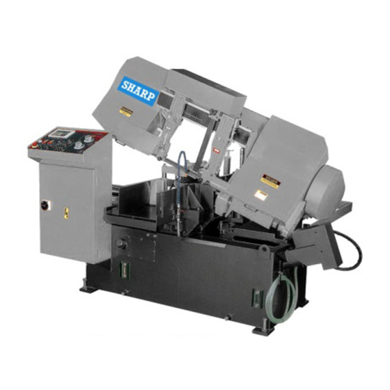
- Page 19 MACHINE PARTS IDENTIFICATION Top Clamp Movable Vise Idler Wheel Drive Wheel Control Panel Chip Conveyor (Option) Vise Water Gauge Control Box...
-
Page 20: Floor Plan
FLOOR PLAN Machine top view... - Page 21 Machine front view Machine side view...
-
Page 23: Moving & Installation
Section 3 MOVING & INSTALLATION LOCATION & ENVIRONMENT UNPACKING & INSPECTING LIFTING REMOVING SHIPPING BRACKET CLEANING INSTALLING RELOCATING LOCATION & ENVIRONMENT For your safety, please read all information regarding installation before proceeding. Install your machine in a place satisfying all of the following conditions: Space: ... -
Page 24: Unpacking & Inspecting
UNPACKING & INSPECTING Unpack your machine carefully to avoid damage to machine parts or surfaces. Upon arrival of your new band saw, please confirm that your machine is the correct model and it comes in the same specification you ordered by checking the model plate on the machine base. ... -
Page 25: Lifting
LIFTING When moving the machine, we strongly suggest you choose any one of the methods described below to move your machine. (Only applies to the machine with the design of the hanging point.) Move the machine to its location by using a crane and a wire rope sling that can fully withstand the weight of the machine (refer to machine specification under Section 2 General Information). - Page 26 When you work together with more than two people, it is best to keep constant verbal communication with each other. Use a forklift (Only applies to the machine with the design of the lifting point.) Make sure that the lifting rod can fully withstand the weight of the machine. (Refer to Section 2 – General Information for Specifications.) Machine lifting with a forklift should be done strictly according to the lifting points designated by the original manufacturer.
- Page 27 3. Use rolling cylinders You can use rolling cylinders to move your machine in a small machine shop environment. You must use rolling cylinders made in material of proper compressive strength. 4. Other ways to move If the machine does not have stickers, please contact your local agent immediately.
-
Page 28: Illustration: Lifting Points
Illustration: Lifting Points Lifting Point Lifting Point Lifting Point Lifting Point Machine top view Minimum weight capacity for each wire rope: 3 ton Total number of wire ropes required: 4... -
Page 29: Removing Shipping Bracket
REMOVING SHIPPING BRACKET After the machine has been properly positioned, remove the shipping bracket that is used to lock the saw frame and the saw bed. Retain this bracket so that it can be used again in the event that your machine must be relocated. -
Page 30: Supplying Coolant
Supplying coolant Fill the coolant tank to the middle level of the sight gauge by pouring the coolant from above the chip conveyor. Use the sight gauge to check the coolant level remaining in the tank. Always check the coolant supply before starting the machine. -
Page 31: Leveling
Turn off the shop circuit breaker. Make sure the machine circuit breaker switch on the electrical compartment door is turned to OFF. Remove the screw securing the electrical compartment and then open the door. Pull the power supply cable and grounding conductor through the power supply inlet into the electrical compartment. -
Page 32: Anchoring The Machine
Anchoring the machine Normally there is no need to anchor the machine. If the machine is likely to vibrate, fix the machine to the floor with anchor bolts. Shock absorption steel plates are provided and can be placed under each leveling bolt to prevent their sinking into the concrete floor. -
Page 33: Operating Instruction
Section 4 OPERATING INSTRUCTION SAFETY PRECAUTIONS BEFORE OPERATING CONTROL PANEL STANDARD ACCESSORIES OPTIONAL ACCESSORIES UNROLLING & INSTALLING THE BLADE ADJUSTING WIRE BRUSH ADJUSTING SAW ARM ADJUSTING COOLANT FLOW PLACING WORKPIECE ONTO WORKBED POSITIONING WORKPIECE FOR CUTTING ADJUSTING BLADE SPEED BREAKING-IN THE BLADE TEST-RUNNING THE MACHINE CUTTING OPERATION STARTING AN AUTOMATIC OPERATION... -
Page 34: Safety Precautions
SAFETY PRECAUTIONS For your safety, please read and understand the instruction manual before you operate the machine. The operator should always follow these safety guidelines: The machine should only be used for its designated purpose. Do not wear gloves, neckties, jewelry or loose clothing/hair while operating the machine. ... -
Page 35: Before Operating
BEFORE OPERATING Choosing an appropriate saw blade and using the right cutting method is essential to your cutting efficiency and safety. Select a suitable saw blade and cutting method based on your work material and job requirements e.g. cutting accuracy, cutting speed, economic concern, and safety control. Wet cutting If you choose dry cutting or low-speed cutting, the chips may accumulate in machine parts and may cause operation failure or insulation malfunction. -
Page 36: Control Panel
CONTROL PANEL The control panel is located on the top of the electrical box. It includes the following function: power system, hydraulic system, cooling system and the human-machine–interface (HMI). The operator must fully understand the function of each switch and button before operating the machine. Name Name Emergency stop button... -
Page 37: Control Buttons
Control Buttons 1. Emergency stop button Press this button to stop the machine in an emergency. When the button is pressed, it brings the machine to a full stop. The button locks when pressed. In order to unlock it, please turn the button clockwise. - Page 38 9. Feed forward When this button is pressed, the feeding workbed will move forward. Press and hold the button to feed forward. As soon as the button is released, the feeding workbed will stop moving forward. This button only works when the machine is switched to manual mode “ ”. ...
-
Page 39: Blade Descend Pressure & Speed Control Panel
Blade descend pressure and speed control panel The part of control panel is where cutting pressure and saw bow descend speed can be adjusted. 1. Cutting pressure control knob This pressure control knob is used to adjust the cutting pressure of the blade. ... - Page 40 Please pay attention to the following environment conditions necessary for HMI touch screen to properly operate: Item Range Ambient temperature 5℃ ~ 50℃ Temperature for safe -10℃ ~ 60℃ operation Ambient humidity 30%~85% RH (No condensation) Connection RS422 MMI port Environment No condensation and rust Main control menu...
- Page 41 Refer to the table below for descriptions of each function. Item Function Description Hydraulic start When the power is turned on, press this button to start the hydraulic motor. A solid yellow icon indicates the hydraulic system has been turned on. Hydraulic stop Press this button to turn off the hydraulic motor immediately.
- Page 42 Item Function Description individual cut is finished. Switching to manual mode at any time other than cutting, the machine will proceed with the next cut until it is finished. Material retract 2mm When this function is turned on, the machine will retract the material for 2mm after completing each cut before the blade ON/OFF rises from its lowest position.
- Page 43 Item Function Description System parameter Press this button to set up system parameters. Password is required. setting All parameters have been set up by the manufacturer. In order to prevent random change from being made to these parameters and affect cutting precision and machine life, this function is protected with a set of password.
- Page 44 Item Function Description Front vise status Indicates if the front vises have clamped and secured the workpiece. indicator When the front vises have secured the workpiece, the clamping vise icon on the right will turn solid white. Feeding movement When the feeding vise reaches the front limit, the vise set indicator icon will turn solid white.
- Page 45 Cutting status display & setup When cutting is in operation, press to enter cutting status display and setup page. Page 1 – cutting status display 1 This page shows the following information (from top to bottom): Feeding length (current feeding vise position) ...
- Page 46 for three seconds. Blade Life Reset - Reset the blade life to zero Press Home to return to the main control menu. Press PGUP to go back to the previous setup page. Press NEXT to go to the next setup page. For machines with optional blade deviation detector installed, additional two command are provided: ...
- Page 47 Cutting program setup When cutting is in operation, press to quickly access the cutting program setup page (the same as page 3 of the cutting status display and setup page) This setup page is the same as page 3 of the cutting status display and setup page.
- Page 48 Error report Page 1 – error report Lists a historical report of the errors and the time of occurrence. Press Home to return to the main control menu. Press Next to go to the troubleshooting support page. Page 2 –...
- Page 49 Error Error Description Solution Code M300 Front vises not clamping Check if the queen valve works M301 Rear vises not clamping Check if the queen valve works M303 Lower limit switch error Check if the lower limit switch works M304 Hydraulic motor not starting Check if the hydraulic motor works M306...
-
Page 50: Standard Accessories
STANDARD ACCESSORIES Blade tension device This blade tension device equipped with hydraulic cylinder provides appropriate tension to the saw blade. To tighten the saw blade, turn the selector to Upon saw blade breakage, the safety device will activate and automatically stop all machine operation. - Page 51 Quick approach device This device allows the blade to quickly descend to just right above the material to save you operation time. Split front vises The spilt vises are a clever design to make sure your workpiece is tightly clamped by the two vises from both sides of the blade, maximizing stability and cutting precision.
-
Page 52: Optional Accessories
OPTIONAL ACCESSORIES Vise pressure regulator This adjustment valve is used to control vise pressure. Adjust vise pressure based on the material of your workpiece. When cutting pipes or soft materials, reduce vise pressure to Pressure prevent exerted pressure from damaging the workpiece shape adjusting or exterior. - Page 53 Hydraulic top clamps The top clamp device composed of two clamps is installed on top of the front and rear vises before executing bundle cutting. Refer to Using Top Clamp for Bundle Cutting for operating procedure on bundle cutting. 2M roller table ...
- Page 54 How to Adjust 1. Loosen the nuts. 2. Adjust the proximity sensor until the blade deviation value shown the display returns to zero. 3. Tighten the nuts. How to Check Put a thick ruler (0.1mm) between saw blade and deviation roller for measurement. Also, check the deviation tilt value;...
- Page 55 Picture B : Deviation Value Display (Shown on HMI display) Make the proximity sensor connect with power & adjust the proximity Deviation Value sensor until the blade deviation displayed on the control panel is 0 mm 。 Tolerance: ±0.03 mm (0.0012”) 。 Deviation Value Set- Picture C: Deviation Value Set-Up &...
-
Page 56: Unrolling & Installing The Blade
NROLLING & INSTALLING THE BLADE Always wear leather gloves and protection glasses when handling a blade. Unrolling the blade Please follow the procedures illustrated below. Unroll and roll the blade Installing a new blade Step 1 - Select the most suitable saw blade for your workpiece considering the size, shape and material. - Page 57 Tension Controller Handle ※ For some model (NO Shown): Handle to Counterclockwise direction => to release saw blade tension Handle to C lockwise direction => to tighten saw blade tension Step 7 - Open the idler and drive wheel covers. Step 8 –...
- Page 58 。 Step 12 – Uninstall protection cover of saw blade (if necessary) for easily taking out the old blade (for CE model only) protection cover of saw blade Step 13 - Remove the old blade. If necessary, clean the carbide inserts before installing a new saw blade.
-
Page 59: Adjusting Wire Brush
ADJUSTING WIRE BRUSH Follow these steps to adjust wire brush to appropriate position: Step 1 - Loosen the lock lever and the wire brush cover. Step 2 - Adjust the screw to make brush move up / down until it makes proper contact with the saw blade (see below illustration). -
Page 60: Adjusting Coolant Flow
Step 3 – Use the flow control valve (shown below) to adjust the amount of fluid flowing to the cutting area. Adjust the flow amount if you observe the following changes to the chips generated from cutting. If the chips are sharp and curved, increase the coolant flow amount. If the chips are granulated, decrease the coolant flow amount. -
Page 61: Positioning Workpiece For Cutting
POSITIONING WORKPIECE FOR CUTTING Follow these steps to position your workpiece: Step Action Press the rear vise clamp button until the workpiece is securely rear vises clamp material clamped. Move the vertical alignment rollers toward workpiece until it align vertical rollers stands against the workpiece. -
Page 62: Breaking-In The Blade
BREAKING-IN THE BLADE When a new saw blade is used, be sure to first break in the blade before using it for actual, extended operation. Failure to break in the blade will result in less than optimum efficiency. To perform this break-in operation, the following instructions should be followed: Step 1 - Reduce the blade feed speed to one-half of its normal setting. -
Page 63: Cutting Operation
CUTTING OPERATION Step 1 – Check before you cut Power: Check the voltage and frequency of your power source. Coolant: Check if you have sufficient coolant in the tank. Hydraulic: Check if you have sufficient (at least two-thirds or higher) hydraulic oil. ... -
Page 64: Starting An Automatic Operation
STARTING AN AUTOMATIC OPERATION Step 1 – Use manual mode and cut the edge of the workpiece by using the same procedures as those described under manual operation. Step 2 – After the trim cut is completed and the saw blade has stopped at the lower limit position, press the saw blade up button to raise the saw bow until the quick approach bar is approximately 10mm (0.4inch) above the workpiece. -
Page 65: Terminating A Cutting Operation
Proper and improper stacking of workpieces Proper Improper Step 4 – Align the top clamp cylinders with the center of the workpiece and tighten the lock nuts. Step 5 – Turn the top clamp handles so that the clearance between the top clamp jaw and the top of the bundled workpiece is within 5 to 10 mm ( 0.2 ~ 0.4 in). -
Page 67: Electrical System
Section 5 ELECTRICAL SYSTEM ELECTRICAL DIAGRAMS... - Page 68 ...
- Page 69 SW-180NC CONTROL PANEL LAYOUT...
- Page 70 SW-180NC CIRCUIT BOARD LAYOUT...
- Page 71 SW-180NC POWER SUPPLY LAYOUT...
- Page 72 SW-180NC PLC INPUT/OUTPUT LAYOUT...
-
Page 73: Hydraulic System
Section 6 HYDRAULIC SYSTEM HYDRAULIC DIAGRAMS... -
Page 75: Bandsaw Cutting: A Practical Guide
Section 7 BANDSAW CUTTING: A PRACTICAL GUIDE INTRODUCTION SAW BLADE SELECTION VISE LOADING BladeBreak -In... - Page 76 INTRODUCTION TPI: The number of teeth per inch as measured from gullet to gullet. 2. Tooth Rake Angle: The angle of the tooth face measured with respect to a line perpendicular to the cutting direction of the saw. 3.Tooth Pitch: Tooth pitch refers to the number of teeth per inch (tpi). 1 inch equates to 25.4 mm. A distinction is made between constant tooth pitches with a uniform tooth distance, 2 tpi for example, and variable tooth pitches with different tooth distances within one toothing interval.
-
Page 77: Vise Loading
4. Tooth pitch The main factor here is the contact length of the blade in the workpiece. If it is 4P, 25.4 ÷ 4 P = 6.35 mm, that is, one tooth is 6.35 mm. If it is 3P, 25.4 ÷ 3 P = 8.46 mm If the number is small, it means that the tooth is large. What is written as 3/4 is that it is a variable pitch of large (3) / small (4). -
Page 78: Bladebreak -In
The following diagrams suggest some costeffective ways of loading and fixturing. Be sure, regardless of the arrangement selected, that the work can be firmly secured to avoid damage to the machine or injury to the operator. BladeBreak -In Completing a proper break-in on a new band saw blade will dramatically increase its life. 1. -
Page 79: Maintenance & Service
Section 8 MAINTENANCE & SERVICE INTRODUCTION BASIC MAINTENANCE MAINTENANCE SCHEDULE BEFORE BEGINNING A DAY’S WORK AFTER ENDING A DAY’S WORK Every 2 weeks First 600hrs for new machine,then every 1200hrs for routine change EVERY SIX MONTHS STORAGE CONDITIONS TERMINATING THE USE OF MACHINE OIL RECOMMENDATION FOR MAINTENANCE INTRODUCTION For the best performance and longer life of the band saw machine, a maintenance schedule is... - Page 80 MAINTENANCE SCHEDULE We suggest you do the maintenance on schedule. Before beginning a day’s work 1. Please check the hydraulic oil level. If oil level volume is below 1/2, please add oil as necessary.(Filling up to 2/3 level is better for system operation.) 2.
- Page 81 Every six months 1.Clean the filter of the cutting fluid. 2.Replace the transmission oil for every half of a year(or 1200 hours). Check the sight gauge to ascertain the transmission level. Recommended TRANSMISSION OIL Omala oil HD220 Mobil comp 632 600W Cylinder oil 3.Replace the hydraulic oil.
- Page 82 OIL RECOMMENDATION FOR MAINTENANCE Item Method Revolution Suggest oil Dovetail guide Keep grease covered. Antirust. Daily Shell R2 Roller bearing Sweep clean and oil with lubricant. Daily SEA #10 Bed roller / surface Sweep clean and oil with lubricant. Daily SEA #10 Nipples of bearing Use grease gun, but not excess.
-
Page 83: Precautions
Section 9 TROUBLESHOOTING INTRODUCTION PRECAUTIONS GENERAL TROUBLES & SOLUTIONS MINOR TROUBLES & SOLUTIONS MOTOR TROUBLES & SOLUTIONS BLADE TROUBLES & SOLUTIONS SAWING PROBLEMS & SOLUTIONS RE-ADJUSTING THE ROLLER TABLE INTRODUCTION All the machines manufactured by us pass a 48 hours continuously running test before shipping out and we are responsible for the after sales service problems during the warranty period if the machines are used normally. - Page 84 PRECAUTIONS When an abnormality occurs in the machine during operation, you can do it yourself safely. If you have to stop machine motion immediately for parts exchanging, you should do so according to the following procedures: Press HYDRAULIC MOTOR OFF button or EMERGENCY STOP button. ...
-
Page 85: Motor Troubles & Solutions
MINOR TROUBLES & SOLUTIONS TROUBLE PROBABLE CAUSE SUGGESTED REMEDY Saw blade motor does not run Overload relay activated Reset even though blade drive button Saw blade is not at forward Press SAW FRAME is pressed. limit position. FORWARD button MOTOR TROUBLES & SOLUTIONS TROUBLE PROBABLE CAUSE SUGGESTED REMEDY... -
Page 86: Blade Troubles & Solutions
BLADE TROUBLES AND SOLUTIONS DISCONNECT POWER CORD TO MOTOR BEFORE ATTEMPTING ANY REPAIR OR INSPECTION. TROUBLE PROBABLE CAUSE SUGGESTED REMEDY Too few teeth per inch Use finer tooth blade Loading of gullets Use coarse tooth blade or cutting lubricant. Teeth strippage Excessive feed Decrease feed... -
Page 87: Sawing Problems & Solutions
SAWING PROBLEMS AND SOLUTIONS Other than this manual, the manufacturer also provides some related technical documents listed as follows: Sawing Problems and Solutions Vibration during cutting Failure to cut Short life of saw blade Curved cutting Broken blade ... - Page 88 SOLUTIONS TO SAWING PROBLEMS Table Of Contents #1. Heavy Even Wear On Tips and Corners Of Teeth #11. Uneven Wear Or Scoring On The Sides Of Band #2. Wear On Both Sides Of Teeth #12. Heavy Wear And/Or Swagging On Back Edge #3.
- Page 89 #2. Wear On Both Sides Of Teeth Probable Cause : A. Broken, worn or missing back-up guides allowing teeth to contact side guides. B. Improper side guides for band width. C. Backing the band out of an incomplete cut. #3. Wear On One Side Of Teeth Probable Cause : A.
- Page 90 #5. Body Breakage Or Cracks From Back Edge Probable Cause : A. Excessive back-up guide "preload" will cause back edge to work harden which results in cracking. B. Excessive feed rate. C. Improper band tracking – back edge rubbing heavy on wheel flange.
- Page 91 #8. Gullets Loading Up With Material Probable Cause : A. Too fine of a tooth pitch – insufficient gullet capacity. B. Excessive feeding rate producing too large of a chip. C. Worn, missing or improperly positioned chip brush. D. Insufficient sawing fluid due to inadequate supply, improper ratio and/or improper application.
- Page 92 #12. Heavy Wear And/Or Swagging On Back Edge Probable Cause : A. Excessive feed rate. B. Excessive back-up guide "preload". C. Improper band tracking – back edge rubbing heavy on wheel flange. D. Worn or defective back-up guides. #13. Butt Weld Breakage Probable Cause : A.
- Page 93 #16. Body Breakage Or Cracks From Gullets Probable Cause : A. Excessive back-up guide "preload". B. Improper band tension. C. Guide arms spread to maximum capacity. D. Improper beam bar alignment. E. Side guide adjustment is too tight. F. Excessively worn teeth. #17.
-
Page 94: Re-Adjusting The Roller Table
#20. Broken Band Shows A Twist In Band Length Probable Cause : A. Excessive band tension B. Any of the band conditions which cause the band to be long (#18) or short (#19) on tooth edge. C. Cutting a tight radius. RE-ADJUSTING THE ROLLER TABLE If the feeding table suffers the huge stroke and the alignment is effected, follow the below procedure to adjust. -
Page 95: Parts
Section 10 PARTS SPARE PARTS RECOMMENDATIONS PART LIST SPARE PARTS RECOMMENDATIONS The following table lists the common spare parts we suggest you purchase in advance: Part Name Part Name Saw blade Coolant tank filter Wire brush Steel plates Carbide inserts Rollers Bearings Belt... - Page 97 10_2...
- Page 98 10_3...
- Page 99 10_4...
- Page 100 10_5...
- Page 101 10_6...
- Page 102 10_7...
- Page 103 10_8...
- Page 104 10_9...
- Page 105 10_10...
- Page 106 10_11...
- Page 107 10_12...
- Page 108 10_13...
- Page 109 10_14...
- Page 110 10_15...
- Page 111 10_16...
- Page 112 10_17...
- Page 113 10_18...
- Page 114 10_19...
- Page 115 10_20...
- Page 116 10_21...
- Page 117 10_22...
- Page 118 10_23...
- Page 119 10_24...
- Page 120 10_25...
- Page 121 10_26...
- Page 122 10_27...