Table of Contents
Advertisement
Available languages
Available languages
Advertisement
Table of Contents

Related Manuals for Honeywell Carnegie


Summary of Contents for Honeywell Carnegie
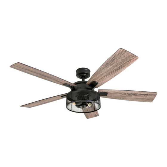
- Page 1 Carnegie Ceiling Fan User Guide Model #50614...
-
Page 2: Package Contents
PACKAGE CONTENTS Canopy Canopy Cover Mounting Bracket Screw (x 4) Mounting Bracket Downrod Downrod Pin Downrod Clip Yoke Cover Closemount Set Screw Screw (x 3) Yoke Motor Assembly Motor Screw (x 10) Fitter Plate Blade (x 5) Blade Arm (x 5) Fitter Plate Screw (x 3) Light Kit Remote Pack... -
Page 3: Safety Information
SAFETY INFORMATION Please read and understand this entire manual before attempting to assemble, operate or install the product. • Before you begin installing the fan, disconnect the power by removing fuses or turning off the circuit breakers. • Make sure all electrical connections comply with local codes, ordinances, the National Electrical Code and ANSI/NFPA 70-199. -
Page 4: Initial Installation
PREPARATION Before beginning the assembly of this product, ensure all parts are present. Compare all parts with the package contents list and hardware contents list. If any part is missing or damaged, do not attempt to assemble the product. Estimated assembly time: 2 hours Tools required (not included): Electrical tape, Phillips Screwdriver, Safety Glasses, Step Ladder, and Wire Strippers. - Page 5 STANDARD OR ANGLE MOUNT INSTRUCTIONS 1. Remove the downrod pin and downrod clip from the downrod. Then partially loosen the set screws in the yoke at the top of the motor assembly (Figure 3.1). 2. Feed the fan wires through the yoke cover, canopy and downrod (Figure 3.2). 3.
-
Page 6: Final Installation
CLOSEMOUNT INSTRUCTIONS (optional) 1. Remove the canopy cover from the bottom of the canopy (Figura 4.1). 2. Remove the three Phillips-head closemount screws from the top of the motor assembly. Then align the canopy with the holes in the top of the motor assembly. The larger holes in the canopy will encompass the remaining screws. Secure the canopy to the top of the motor assembly with the previously removed closemount screws (Figura 4.2). - Page 7 FINAL INSTALLATION 4. Partially insert the blade screws along with lock washer and blade washer through blade and into the blade arm. Tighten each blade screw starting with the one in the middle (Figure 5.4). Repeat this step for the remaining blades and blade arms (Figura 5.4). 5.
- Page 8 FINAL INSTALLATION 10. If desired, the wall bracket in remote pack can be installed to a wall using the provided mounting screws. The remote can be stored in the mounting bracket for easy access (Figure 5.10). 11. Turn on power to fan at breaker box and the wall switch (Figure 5.11). Assembly is complete. Screw Wall Bracket...
-
Page 9: Troubleshooting
TROUBLESHOOTING If you experience any faults, please check the Troubleshooting section below. If a problem cannot be remedied or you are experiencing difficulty in installation, please contact Customer Service: 1-877-361-3883. Warning: Shut off the power supply before you begin any maintenance task. PROBLEM CORRECTIVE ACTION 1. -
Page 10: Limited Lifetime Warranty
4L000008650 Mounting Bracket 4L000006350 Canopy 4A000009330 Canopy Cover 4L000008590 The Honeywell Trademark is used under license from Light Kit 4A000009340 Honeywell International Inc ™. Remote Pack 4A000008300 Honeywell International Inc. makes no representations or warranties with respect to this product. - Page 11 Ventilador de techo Carnegie Guía del usuario Modelo #50614...
-
Page 12: Contenido Del Paquete
CONTENIDO DEL PAQUETE Base Cubierta de la base Tornillo para soporte de montaje (x 4) Soporte de montaje Varilla Pasador de la varilla Sujetador de la varilla Cubierta de horquilla Tornillo de fijación (x 2) Tornillo de montaje cerrado (x 3) Horquilla Ensamble del motor Tornillo del motor (x 10) -
Page 13: Información De Seguridad
INFORMACIÓN DE SEGURIDAD Por favor lea y entienda la totalidad de este manual antes de intentar ensamblar, operar o instalar el producto. • Antes de que comience a instalar el ventilador, desconecte el suministro eléctrico retirando los fusibles o apagando el interruptor cortacircuitos. -
Page 14: Instalación Inicial
PREPARACIÓN Antes de comenzar a ensamblar este producto, asegúrese de tener todas las piezas. Compare todas las piezas con la lista del contenido del paquete y la lista de aditamentos. No intente ensamblar el producto si falta alguna pieza o si estas están dañadas. Tiempo estimado de ensamblaje: 2 horas Herramientas necesarias para el ensamblaje (no se incluyen): cinta aislante, destornillador Phillips, pinza, gafas de seguridad, escalera de tijera, pinza pelacables... - Page 15 INSTRUCCIONES DE MONTAJE ESTÁNDAR O EN ÁNGULO 1. Retire el sujetador de la varilla y el pasador de la varilla de la varilla. Luego afloje parcialmente los tornillos de fijación que se encuentran en la horquilla de la parte superior del ensamble del motor (Figura 3.1). 2.
-
Page 16: Instalación Final
INSTRUCCIONES PARA MONTAJE CERRADO (opcional) 1. Retire la cubierta de la base de la parte inferior de la base (Figura 4.1). 2. Retire tres tornillos de montaje cerrado con cabeza Phillips de la parte superior del ensamble del motor. Luego, alinee los orificios de la parte inferior de la base con los orificios para tornillo de la parte superior de la carcasa del motor. - Page 17 INSTALACIÓN FINAL 4. Inserte parcialmente los tornillos de las aspas junto con las arandelas de seguridad y las arandelas de las aspas a través de un aspa y en un brazo de las aspas. Apriete cada tornillo del aspa, comenzando por el que está en el medio. Repita este paso para las aspas restantes y los brazos de las aspas (Figura 5.4).
-
Page 18: Instrucciones De Funcionamiento
INSTALACIÓN FINAL 10. Si lo desea, el soporte de pared del paquete remoto puede instalarse sobre una pared con los tornillos de montaje proporcionados. Guarde el control remoto en el soporte de pared cuando no se utilice (Figura 5.10). 11. Encienda la energía mediante el interruptor cortacircuitos y el interruptor de pared (Figura 5.11). El ensamblaje está listo. Tornillo Soporte en pared... -
Page 19: Solución De Problemas
SOLUCIÓN DE PROBLEMAS Si experimenta alguna falla, verifique la sección Solución de problemas a continuación. Si el problema no se puede solucionar o experimenta dificultades en la instalación, póngase en con contacto con el Departamento de Servicio: 1-877-361-3883. Advertencia: antes de realizar cualquier trabajo de mantenimiento, desconecte el suministro de electricidad principal. PROBLEMA ACCIÓN CORRECTIVA 1. -
Page 20: Garantía Limitada De Por Vida
8 a.m. a 6 p. m., y los viernes de 8 a. m. a 5 p. m., hora estándar del Este. Varilla 4L000008650 Soporte de montaje 4L000006350 Base 4A000009330 El Honeywell Marca es acostumbrado Cubierta de la base 4L000008590 marco carné de Honeywell Internacional Citada. Kit de iluminación 4A000009340 Honeywell Internacional Citada.