Table of Contents
Advertisement
CF3680 2D Imager Module
For Customer-Facing Designs
Quick Start Guide
Aller à
www.honeywellaidc.com
Vai a
www.honeywellaidc.com
Gehe zu
www.honeywellaidc.com
Ir a
www.honeywellaidc.com
日本語 :
www.honeywellaidc.com
如要到中国 www.honeywellaidc.com(简体) 。
查看繁体版请登陆
한글
www.honeywellaidc.com
pour le français.
per l'italiano.
para español.
www.honeywellaidc.com
로 이동합니다 .
für Deutsch.
をご覧ください。
CF3680-EN-QS-01 Rev B
2/17
Advertisement
Table of Contents

Related Manuals for Honeywell CF3680


Summary of Contents for Honeywell CF3680
- Page 1 CF3680 2D Imager Module For Customer-Facing Designs Quick Start Guide Aller à www.honeywellaidc.com pour le français. Vai a www.honeywellaidc.com per l'italiano. Gehe zu www.honeywellaidc.com für Deutsch. Ir a www.honeywellaidc.com para español. 日本語 : をご覧ください。 www.honeywellaidc.com 如要到中国 www.honeywellaidc.com(简体) 。 查看繁体版请登陆 www.honeywellaidc.com 한글...
-
Page 2: Required Accessories
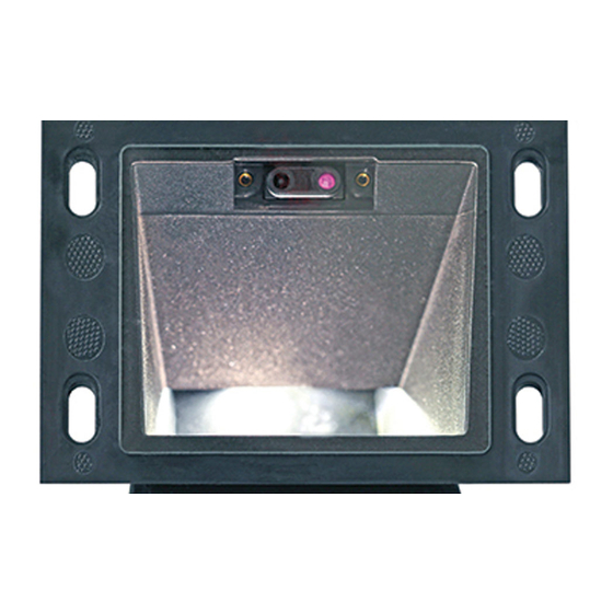
What is the CF3680 2D Imager Module? The CF3680 is a 2D imager module designed to be integrated into fixed mount enclosures, such as a self-service kiosk. It includes: • N3680 scan engine • USB interface (USB-B connector) • Exit window •... - Page 3 CF3680 Front View Mounting holes (x4) Exit window...
- Page 4 CF3680 Back View Ribbon cable sensor to PCB Ribbon cable engine to PCB Movement detector Scan engine USB-B connector Distance selection switch User feedback pins...
-
Page 5: Pcb View
PCB View Flex connector to movement detector USB-B connector User feedback pins Distance selection switch Flex connector to scan engine... - Page 6 CF3680 and to the USB port on the host. Power-up the host. Verify that the CF3680 is on by presenting a bar code in front of the scan window. The white LED should turn on and read the bar code.
- Page 7 Distance Selection Switch Use this switch to select the range to be used to detect an object and trigger the scan engine. The distance is measured from the outside of the exit window. • Position 1—0 to 10 cm (4 in) •...
-
Page 8: Configuration Bar Codes
Configuration Bar Codes Scan configuration bar codes to set up your scanner. All avail- able configuration bar codes are available in the N3680 User’s Guide. Contact your local Honeywell OEM representative for more information. EZConfig Cloud for Scanning Tool Use the EZConfig Cloud for Scanning tool to configure your... -
Page 9: Basic Setup
Basic Setup Here are some basic menu bar codes that may be useful for test- ing. For more setup options see the N36810/CF3680 User Guide (available from your local Honeywell OEM representa- tive). Note: The * symbol indicates the default value. -
Page 10: Keyboard Country Layout
Keyboard Country Layout The default keyboard is United States. French German Italian All Symbologies All Symbologies On All Symbologies Off... -
Page 11: Reset Factory Defaults
LED Illumination - Manual Trigger Use this setting to change the LED illumination brightness. Low * High Reset Factory Defaults The following bar code resets factory defaults. -
Page 12: Mechanical Dimensions
Mechanical Dimensions... - Page 14 Mounting hole recess (section A-A)
-
Page 15: Exit Window
User Feedback Pins User feedback pins give you access to the trigger, beeper and good read lines on the scan engine. See the CF3680 Installation Guide for details on these pins (available from your local Honey- well OEM representative). Exit Window The exit window is made of chemically strengthened glass and is scratch resistant. -
Page 16: Limited Warranty
Patents For patent information, please refer to www.hsmpats.com. Disclaimer Honeywell International Inc. (“HII”) reserves the right to make changes in specifications and other information contained in this document without prior notice, and the reader should in all cases consult HII to determine whether any such changes have been made.