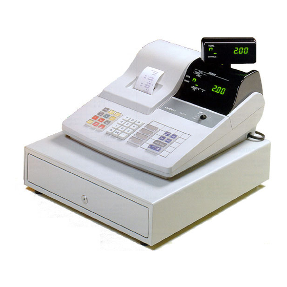
Casio 200CR Service Manual
Hide thumbs
Also See for 200CR:
- Operator's instruction manual (76 pages) ,
- Most important functions (5 pages)

Related Manuals for Casio 200CR


Summary of Contents for Casio 200CR
- Page 1 SERVICE MANUAL (without price) ELECTRONIC CASH REGISTER 200CR/PCR-360/PCR-365 (EX-245) (WHC) (OSS) 240CR/PCR-460 (EX-246) AUGUST 1996 Printer Model : M405R...
-
Page 2: Table Of Contents
5-11. Error code ...................... 20 6. How to open upper case ..................21 7. Remove the drawer ....................22 8. Parts layout ......................23 9. Circuit diagrams ....................25 10. Parts list (200CR/PCR-360/PCR-365) ..............41 11. Parts list (240CR/PCR-460) ................... 52... -
Page 3: Features
1. Features The difference between 200CR and 240CR is as follows: Function 200CR/PCR-360/PCR-365 240CR/PCR-460 POP display Available Stamp function Available Customer display Available Available Power protection function LED transaction Available EEPROM Available (except PCR-460) Calculator function Available Available 2. Specifications (200CR/PCR-360/PCR-365/240CR/PCR-460) 2-1. -
Page 4: Principal Components
2-3. Principal components µPD78054GC-213-3B9 (200CR etc.) • CPU Name µPD78054GC-214-3B9 (240CR etc.) Number of control bit Internal RAM 1024 B Internal ROM 32 KB Main system clock 5.00 MHz Sub system clock 32.768 KHz • RAM Name LC3564S70/85/10 Capacity 8 KB... -
Page 5: Mac (Memory All Clear) Operation
3. Mac (Memory All Clear) operation Procedure A (1) Plug the power cord into an outlet. (2) Pressing the FEED button and turn the mode switch to PRG position. (3) Release the FEED button. After few seconds, MAC operation will be executed. (4) The following receipt will be issued, if completed. -
Page 6: Diagnostic Operation
4. Diagnostic operation 4-1. How to start (1) Plug the power cord into an outlet. (2) Execute the MAC operation. (3) Turn the mode switch to “PRG” position. (4) Input 99990000 and press the sub total button. (5) Start the diagnostic program and issues the following receipt. Note : If you have done the registration after MAC operation, the Diagnostic program can not start. -
Page 7: Hard Key Code Check
4-3. Hard key code check When all keys except numerical keys, Clear key and FEED keys are pressed directly, the machine displays the hard key code as shown below. Hard key code (2 digits) Hard key code table Hard key code 047 041 035 029 023 017 055 051 046 040 034 028 022 016... -
Page 8: Print Test
3) RAM write and read check The machine writes data into RAM and read out the data to compare with written data. When this check is finished correctly, the machine goes to check No. 4). However, if an error is occurred, the machine sounds an error tone, prints the error receipt, and stops Hard check program. -
Page 9: Read Test For Eeprom
4-4-3. Read/write test for EEPROM Operation Execute the Read/write test in test area (1word) of EEPROM. Note: This test is effected on 240CR only. If an error is occurred, the machine sounds an error tone, prints " — — — — — — — 8" on receipt, and stops this test. -
Page 10: All Characters Print Check
4-4-7. All characters print check Operation 0 0 0 0 0 0 0 0 0 1 1 1 1 1 1 1 1 1 2 2 2 2 2 2 2 2 2 3 3 3 3 3 3 3 3 3 4 4 4 4 4 4 4 4 4 5 5 5 5 5 5 5 5 5 6 6 6 6 6 6 6 6 6... -
Page 11: Country Code Write
4-4-9. Country code write Operation Country code Erase the EEPROM and write the country code into EEPROM. Note: This test is effected on 240CR only. < Country code > Code Country : It is no effect because of no EEPROM . Export (ADD2) U.S. -
Page 12: Circuit Explanation
5. Circuit explanation 5-1. Power supply circuit WITH HEAT-SINK 1SR35-100A D1276A LM2575T-5.0 ON/OFF VIN1 VOUT OUTPUT FEED BACK 4.7K C945 TRANS L331K 5277-02A VLED C945 1S2473 1S2473 1SR35-100A : Transistor for controlling voltage (VP) : Transistor for voltage detection : Transistor for controlling power down (PWD) signal ZD2 : Zenner diode for controlling base current of Q2 ZD1 : Zenner diode for detecting power down (PWD) signal After plug the AC cord into the outlet, the 24 volts of AC voltage appears between T1 and T2. - Page 13 [PWD signal] After plug the AC cord into outlet, VP voltage appears on the base terminal of transistor Q3. When the VP exceeds 13 volts, Q3 is turned on by the differential voltage between base and emitter of Q3. Then the PWD signal goes to GND level and informs "power on" to the CPU. When the VP drops less than 13 volts, Q10 is turned off.
-
Page 14: Cpu ( Μ Pd78054Gc)
µ 5-2. CPU ( PD78054GC) P W - O N Pin No. Signal Description In / Out l e v e l Head drive signal (HD1) Stamp drive signal (STAMP) Winder motor drive signal (WINDER) AVss Analong ground for A/D converter —... -
Page 15: Mode Key Switch Status Read
P W - O N Pin No. Signal Description In / Out l e v e l P123 Display segment signal (SEG0d) / Key common singnal (KC2) Pulse P124 Display segment signal (SEG0e ) / Key common singnal (KC1) Pulse P125 Display segment signal (SEG0f) / Key common singnal ( KC0) Pulse... -
Page 16: Ram Address
5-4. RAM address ASTB AD0 ~ AD7 A8 ~ A13 74HC373 A0 ~ A7 D0 ~ D7 CPU is used port 40 ~ 47 (pin No. 19 ~ 26) for address/data bus. CPU sends the address A0 ~ A13 to RAM through the IC5. To select the address A0 ~ A7, CPU send the address AD0 ~ AD7 to IC5. -
Page 17: Data Communication Between Cpu And Eeprom
5-6. Data communication between CPU and EEPROM EEPROM Pin No.23 CS : Chip enable SK : Serial data clock Pin No.14 DI : Serial data input BR93LC66A BR93LC46A DO : Serial data output Pin No.15 Pin No.16 EEPROM is a memory to possible write/erase by electricity . The BR93LC66A privides efficient nonvolatile read/write memory arranged as 64 registers of 16 bits each. - Page 18 [Data reading procedure] When the CPU read the dara of EEPROM, CPU send the CS signal and SK signal to EEPROM. Then, CPU send the address to EEPROM, and then EEPROM send the data to CPU. Address Address Data Data Output data here Output data here [Data writing procedure]...
-
Page 19: Notice Of Display Leds
5-7. Notice of display LEDs This machine is using display LED. Specification of original LED is HDSP-5621#S202. The following LEDs are interchangeable parts. However, its brightness is different. If you replace it for repair, use the same specification. Specification is written here. Specification Parts Code HDSP-5621#S02... -
Page 20: Printer Drive Circuit
5-9. Printer drive circuit Printer Head drive HDCOM circuit M405R HD1 ~ HD13 HD1 ~ HD13 "L"→"H" "H"→"L" Motor Motor "L"→"H" "L"→"H" Motor Motor drive circuit When CPU wants to rotate the mortor, CPU outputs “Motor” signal (L H), and Motor signal goes through the motor drive circuit and then it become “L”.Then Motor rotates because of difference voltage between Motor and Motor COM TERMINAL. - Page 21 3. LM2575T-5. 0/LB03 ON/OFF Unregulated Internal ON/OFF DC Input Regulator Note: Pin numbers are for Imo TO•220 package. Feed Back 3.1K Fixed Csin Error Amp. I AMP. Comparator SWITCH 1.0K Driver OUTPUT Yout = +5V Cout 1.2dY 52KHz Thermal Current Bend-Cep Reset Reference...
-
Page 22: Error Code
5. TC74HC373P The TC74HC373 is a high speed CMOS OCTAL LATCH with 3-STATE OUTPUT fabricated with silicon gate C MOS technology. This IC achieves the high speed operation similar to equivalent LSTTL while maintaining the CMOS low power dissipation. These 8-bit D-type latches are controlled by a latch enable input (LE) and a output enable input (OE). While the LE input is held in high level, the Q outputs will follow the data input precisely or inversely. -
Page 23: How To Open Upper Case
6. How to open upper case 1. Remove the printer cover. 2. Remove the screw 3. Slide the keyboard cover to arrow direction and pull it down to release the hooks 4 and then remove the keyboard cover. 4. Press the hock to display side and pull up the front and remove the upper case. Note: Be sure to stand the customer display before remove the upper case. -
Page 24: Remove The Drawer
7. Remove the drawer 1. Remove the drawer connector. 2. Remove the screws 3. Slide the lower case to arrow direction and pull up the lower case. Drawer connector — 22 —... -
Page 25: Parts Layout
8. Parts layout — 23 —... -
Page 26: Circuit Diagrams
– 2 – TIME TIME TIME ERR. ERR. POST POST POST CORR • CORR • ERR. • TEND TEND TEND RECEIPT CANCEL RECEIPT CANCEL RECEIPT CORR C/AC C/AC C/AC Name Board No. Drawing No. 200CR/PCR-360/PCR-365 BLOCK DIAGRAM E240413 — 25 —... - Page 27 EEPROM CE EX-245 L-WHC 4.7K EX-245 L-OSS 100K EX-245 EX-246 A,B,D,G,BU EX-245 C-OSS BATTERY EX-246 RB721Q 53253-0210 CN11 VLED RB100A TO BLOCK DIAGRAM (2/4) C101 C10 Name Board No. Drawing No. E245-1 200CR/PCR-360/PCR-365 E240414 BLOCK DIAGRAM (1/3) — 26 —...
- Page 28 2 3 4 5 6 SEG1b/KC10 C101*5 C101*5 SEG1a/KC11 1SR35-100A WITH HEAT-SINK D1276A LM2575T-5.0 VIN1 ON/OFF VOUT OUTPUT FEED BACK 4.7K C945 TRANS L331K 5277-02A VLED C945 1S2473 1S2473 1SR35-100A Name Board No. Drawing No. E245-1 200CR/PCR-360/PCR-365 BLOCK DIAGRAM (2/3) E240415 — 27 —...
- Page 29 C-002RX(M90-76) 1S2473-T-77-T 1S2473-T-77-T 1S2473-T-77-T MS1038F 1S2473-T-77-T MS1036F PKM22EPP-2002 1S2473-T-77-T MS5635F 1S2473-T-77-T 1S2473-T-77-T CNB5X101K 1S2473-T-77-T CNB5X101K OWA1419-681K CNB7X101K 1SR35-100A-T-82-T CNB5X101K 1SR35-100A-T-82-T RB100AT-32 Heat sink OSH-1625-SPL RD13EB3-TN-T RD5.6EB3-TN-T Name Board No. Drawing No. E245-1 200CR/PCR-360/PCR-365 BLOCK DIAGRAM (3/3) E240417 — 28 —...
- Page 30 <US. CANADA SPEC.> (C, L) 120V L5T18X6X10 TE-240-E4D <LIMITED AREAS SPEC.> S–J2875–05 240V 230V 220V 120V 100V L5T18X6X10 TE-240-E3U Name Board No. Drawing No. 200CR/PCR-360/PCR-365 POWER SUPPLY E340559 — 29 —...
- Page 31 CN3-1 COM2 COM2 CN3-2 COM1 COM1 CN3-3 COM0 COM0 CN2-9 CN3-4 CN3-10 CN3-11 CN3-6 CN3-7 CN3-5 CN3-8 SDP0 CN3-9 SDP0 CN2-6 CN2-4 CN2-3 CN2-8 CN2-7 CN2-5 CN2-2 CN2-1 Name Board No. Drawing No. 200CR/PCR-360/PCR-365 MAIN DISPLAY E311438 — 30 —...
- Page 32 COM3 CN3-1 COM2 CN3-2 COM1 CN3-3 COM0 CN2-9 CN3-4 CN3-10 CN3-11 CN3-6 CN3-7 CN3-5 CN3-8 CN3-9 SDP0 CN2-6 CN2-4 CN2-3 CN2-8 CN2-7 CN2-5 CN2-2 CN2-1 Name Board No. Drawing No. 200CR/PCR-360/PCR-365 POP UP DISPLAY E311439 — 31 —...
- Page 33 31 32 33 34 35 36 37 38 39 40 41 42 17 18 19 20 21 22 23 24 25 26 27 28 9 10 11 12 13 14 KEY CONTACT POSITION Name Board No. Drawing No. 200CR/PCR-360/PCR-365 KEY BOARD E340555 — 32 —...
- Page 34 POP UP DISPLAY E240-E2 POWER 53254-0910 53254-1110 TRANSFORMER E240-E2 40ms 51015-0900 51015-1100 AC IN 52044-2045 40ms 1.3s 29.4ms 5277-02A DRY BATT. CPU CLK 52045-2045 IL-G-2P R-ON/OFF LED 52045-0245 B3B-PH-K-S 53253-0210 B2B-PH-K-S PRINTER 22019 × 2 WINDER M-405R MOTOR 5229-22APB DRAWER 52045-2545 70us 970us...
- Page 35 5.6k C120 C101*7 C101*7 SEGTR/PAD3 (WHC/OSS) SEGTR C150J 6BA12004 HD1B HD2B PAD3 4 BA12004 HD3B 3 BA12004 HD4B TAX-SW BA12004 HD5B 1 BA12004 HD6B PAD1 BA12004 HD7B C101 PAD2 6 BA12004 HD8B BA12004 IC10 HD9B IC10 4 BA12004 HD10B BA12004 IC10 HD11B IC10...
- Page 36 TO E240-E2 R-ON/OFF LED LED1 52045-2045 B3B-PH-K-S HLMP-S500 C101*8 TO E244-E4 9 8 7 6 5 4 3 2 SDP0 52045-2545 COM3 COM2 COM1 3 2 1 COM0 TO CN3 VLED RAM CE IC2 BA12004 DTC114YS C471 VLED 3.9K DTD113ZS Q13 DTC114YS R28 10K B1240...
- Page 37 Specification Specification Specification Location No. Location No. Location No. LM2575T-5.0/LB03 CR-25-560-OHM-J-T 2SD1276A BA12004 CR-25-1.2K-OHM-J-T 2SC945(K, P, Q, R)-T BA12004 CR-25-3.9K-OHM-J-T 2SC945(K, P, Q, R)-T LC3564S70/85/10 R50X-2K-J-T24-T DTD113ZS-TP-T CXK58257AP-70/10L CR-25-2.2K-OHM-J-T DTC114YSA-TP-T TC74HC373AP 2SB1240V2-Q, R BA93LC66A CR-25-4.7K-OHM-J-T DTC114YSA-TP-T DILB8P-8JK CR-25-1K-OHM-J-T 2SB1240V2-Q, R µPD78054GC-214-3B9 CR-25-10K-OHM-J-T DTC114YSA-TP-T...
- Page 38 <JAPAN SPEC.> <EUROPE> (B, D, F, G) 100V 240V 230V 220V 120V 100V L5T18X6X10 TE-240-E3D L5T18X6X10 TE-240-E3U <US. CANADA SPEC.> (C, L) 120V L5T18X6X10 TE-240-E4D <LIMITED AREAS SPEC.> S–J2875–05 240V 230V 220V 120V 100V L5T18X6X10 TE-240-E3U Name Board No. Drawing No. 240CR/PCR-460 POWER SUPPLY E340557...
- Page 39 LED1 HLMP-S500 × 2 LED2 COM3 COM3 CN3-1 COM2 COM2 CN3-2 COM1 COM1 CN3-3 COM0 COM0 CN2-9 CN3-4 CN3-10 CN3-11 CN3-6 CN3-7 CN3-5 CN3-8 SDP0 CN3-9 SDP0 CN2-6 CN2-4 CN2-3 CN2-8 CN2-7 CN2-5 CN2-2 CN2-1 Name Board No. Drawing No. 240CR/PCR-460 MAIN DISPLAY E311443...
- Page 40 LED1 HLMP-S500 × 2 LED2 COM3 CN3-1 COM2 CN3-2 COM1 CN3-3 COM0 CN2-9 CN3-4 CN3-10 CN3-11 CN3-6 CN3-7 CN3-5 CN3-8 CN3-9 SDP0 CN2-6 CN2-4 CN2-3 CN2-8 CN2-7 CN2-5 CN2-2 CN2-1 Name Board No. Drawing No. 240CR/PCR-460 POP UP DISPLAY E311444 —...
- Page 41 TO E245-1 E266-E3-1 71 72 73 74 75 76 65 66 67 68 69 70 45 46 47 48 49 50 51 52 53 54 55 56 31 32 33 34 35 36 37 38 39 40 41 42 17 18 19 20 21 22 23 24 25 26 27 28 9 10 11 12 13 14 KEY CONTACT POSITION Name...
-
Page 42: Parts List (200Cr/Pcr-360/Pcr-365)
10. Parts list (200CR/PCR-360/PCR-365) 1. MAIN PCB BLOCK 2. UPPER CASE BLOCK 3. MAIN DISPLAY BLOCK 4. CUSTOMER DISPLAY BLOCK 5. KEYBOARD BLOCK 6. POWER SUPPLY BLOCK 7. LOWER CASE BLOCK 8. PRINTER BLOCK 9. WIND MOTOR BLOCK 10. PRINTER COVER BLOCK 11. - Page 43 Japan only Japan only...
- Page 45 PARTS PARTS LIST (200CR/PCR-360/PCR-365) LIST(200CR/PCR-360/PCR-365) I t e m Code No. Parts Name Specification Version 1. MAIN PCB BLOCK 6193 2818 Main PCB ass'y E245-1 E240333*1 Other countries 6193 2825 Main PCB ass'y E245-1 E240333*2 US-OSS 6193 3784 Main PCB ass'y E245-1...
- Page 46 I t e m Code No. Parts Name Specification Version Carbon film resistor CR-25-1.2KOHM-J-T Carbon film resistor CR-25-5.6KOHMJ-T Metal film resistor CRH200-FH24-J-101 Module resistor MS5635F Module resistor MS1038F Module resistor MS1036F C7,8,14,17, TF capacitor ECQ-V1H-104-JZ3 C18,22,23,24, 2807 3533 Electrolytic capacitor RE2-25V330MMA-T2 2807 3540 Electrolytic capacitor RE2-25V331MMA-T2...
- Page 47 I t e m Code No. Parts Name Specification Version 4. CUSTOMER DISPLAY BLOCK 2320 1365 LED HDSP-5621#S02 Carbon film resistor ERD25TJ121V Carbon film resistor ERDS2TJ121V 4306 1004 PCB E240-E2 (without components) E311067A-1 7 6191 0334 Connector ass'y E311301*1 8 6247 6469 Display case E245 E240325-1 9 6247 6476 Rear case E245 E240326-1...
- Page 48 I t e m Code No. Parts Name Specification Version 6. POWER SUPPLY BLOCK 40 3000 3013 Power transformer TE-240-E3U Other countries 40 3000 3015 Power transformer TE-240-E4D US,Canada 41 3030 4055 Ferritte core L5T18X6X10 3600 1046 Voltage selector S-J2875-05 42 3701 0221 Power cord PS5006-B Other countries...
- Page 49 DL-1320 — 48 —...
- Page 50 I t e m Code No. Parts Name Specification Version 12. DRAWER 12-1. DL-1320 (U.S.) 6247 6497 Drawer unit E440386*3 6193 3140 Bill/Coin case ass'y E240112*2 6221 4902 Bill holder ZD18931 6246 5220 Bill holder spring E412160-1 6246 6571 Bill holder fixing plate E311873-1 6246 6585 Partition plate E340010-5...
- Page 51 DL-2762 — 50 —...
- Page 52 I t e m Code No. Parts Name Specification Version 12-2. DL-2762 (Europe, U.K., Germany, other countries) 6247 6448 Drawer unit E440128A*13 6192 7953 Bill/Coin case ass'y E140034*3 6247 3935 Coin case E140058-1 6246 5230 Bill holder fixing plate E211620-1 6247 3949 Coin separater E340173-1 6246 5220 Bill holder spring...
- Page 53 11. Parts list (240CR/PCR-460) 1. MAIN PCB BLOCK 2. UPPER CASE BLOCK 3. MAIN DISPLAY BLOCK 4. CUSTOMER DISPLAY BLOCK 5. KEYBOARD BLOCK 6. POWER SUPPLY BLOCK 7. LOWER CASE BLOCK 8. PRINTER BLOCK 9. WIND MOTOR BLOCK 10. STAMP STAND BLOCK 11.
-
Page 54: Parts List (240Cr/Pcr-460)
PARTS LIST(240CR/PCR-460) PARTS LIST (240CR/PCR-460) I t e m Code No. Parts Name Specification Version 1. MAIN PCB BLOCK 6193 2636 Main PCB ass'y E246-1 E240337*2 6193 2643 Main PCB ass'y E246-1 E240337*3 Except US 2006 1109 EEPROM BR93LC66A Except US 2006 1249 LSI LC3564S70/85/10 Except US... - Page 55 I t e m Code No. Parts Name Specification Version Carbon film resistor CR-25-5.6KOHMJ-T Metal film resistor CRH200-FH24-J-101 Metal film resistor CRH100-FH11J-2R2 Module resistor MS5635F Module resistor MS1038F Module resistor MS1036F C7,8,11,14, TF capacitor ECQV1H104JZ3 10 X C17,18,22,23, C24,26 2807 3533 Electrolytic capacitor RE2-25V330MMA-T2 2807 3540 Electrolytic capacitor RE2-25V331MMA-T2...
- Page 56 I t e m Code No. Parts Name Specification Version Carbon film resistor ERD25TJ121V Carbon film resistor ERDS2TJ121V 3500 5833 PCB connector 52044-2045 3500 5834 Pin ass'y 9P 53254-0910 3500 5835 Pin ass'y 11P 53254-1110 4306 1004 PCB E240-E2 (without components) E311067A-1 6 6221 3781 LED spacer E411332-1 4.
- Page 57 I t e m Code No. Parts Name Specification Version 37 6247 6869 Plate sub ass'y E240347*1 38 6192 4970 Mode key ass'y E311944*1 39 6247 6539 Mode key plate E246B E440374-6 39 6247 6546 Mode key plate E246C E440374-7 Screw with washer 3X8 ZMC-3..
- Page 58 I t e m Code No. Parts Name Specification Version 13. OTHERS 62 6221 4029 Paper holding spool E411393-1 63 6246 1830 Wind pulley E311860-1 64 6246 4000 Key set E312046*2 64 6246 4010 Key set E312046*3 65 6247 8814 Ribbon cover E240315-1 66 6247 8821 Battery cover E340406-1...
- Page 59 DL-1320 — 58 —...
- Page 60 I t e m Code No. Parts Name Specification Version 14. DRAWER 14-1. DL-1320 (U.S.) 6247 6497 Drawer unit E440386*3 6193 3140 Bill/Coin case ass'y E240112*2 6221 4902 Bill holder ZD18931 6246 5220 Bill holder spring E412160-1 6246 6571 Bill holder fixing plate E311873-1 6246 6585 Partition plate E340010-5...
- Page 61 DL-2762 — 60 —...
- Page 62 I t e m Code No. Parts Name Specification Version 14-2. DL-2762 (Canada, other countries) 6247 6448 Drawer unit E440128A*13 6192 7953 Bill/Coin case ass'y E140034*3 6247 3935 Coin case E140058-1 6246 5230 Bill holder fixing plate E211620-1 6247 3949 Coin separater E340173-1 6246 5220 Bill holder spring E412160-1...
- Page 63 DL-1832 — 62 —...
- Page 64 I t e m Code No. Parts Name Specification Version 14-3. DL-1832 (Europe, other countries) 6247 6504 Drawer unit E440386*4 6193 3161 Bill/Coin case ass'y E240112*5 6221 4902 Bill holder ZD18931 6246 5220 Bill holder spring E412160-1 6246 6578 Bill holder fixing plate E311937-1 6246 6585 Partition plate E340010-5...
- Page 65 EXPLODED DIAGRAM FOR M-450R — 64 —...
- Page 66 PARTS LIST (M405R) I t e m Code No. Parts Name Specification Version DRIVE MECHANISM COMPONENTS 1908 5585 Motor ass'y C770052000 1903 0638 C.B. screw B010350511 1908 5586 First reduction gear C770051010 TRANSMISSION MECHANISM COMPONENTS 1908 7302 Second reduction gear C769101000 1903 2606 Third reduction gear C756101020...
- Page 67 I t e m Code No. Parts Name Specification Version 1903 1077 Ribbon shift spring C750353010 1902 5851 Ribbon feeding lever spring C405361010 1903 1123 Ribbon shift magnet ass'y C405355001 1903 0643 Cup screw B040302311 1902 5611 Shift lever spring C401358010 1908 7651 Ribbon frame stopper C757354010...
- Page 68 MA0901561A...