
Related Manuals for C-TEC EP203


Summary of Contents for C-TEC EP203
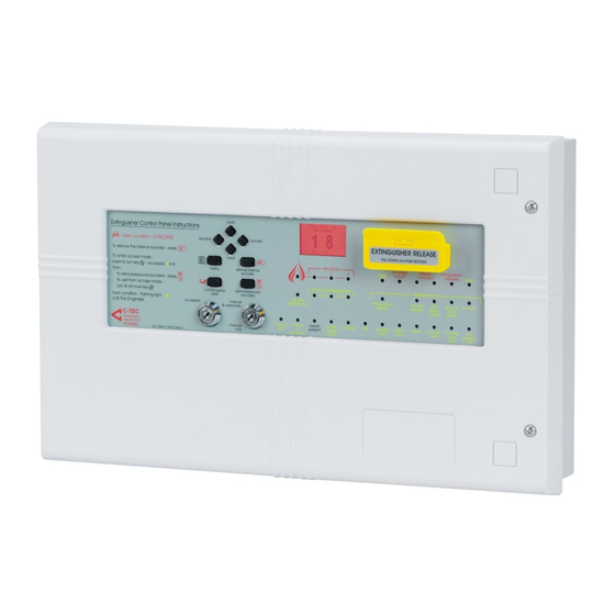
- Page 1 EP203 AUTOMATIC EXTINGUISHER PANEL Installation and Maintenance Manual Approved Document No. DFU0002032 Rev 4 www.acornfiresecurity.com...
-
Page 2: Table Of Contents
Overview ..............................24 Display Faults ............................. 25 Display Dis/mnt ............................25 Zones in Test .............................. 25 Display RSUs..............................25 Disablements.............................. 26 Page 2 of 45 • EP203 AUTOMATIC EXTINGUISHER PANEL INSTALLATION MANUAL • Approved Document No. DFU0002032 Rev 4 www.acornfiresecurity.com... - Page 3 E&OE. Approved Document No. DFU0002032 Rev 4 • EP203 AUTOMATIC EXTINGUISHER PANEL INSTALLATION MANUAL • Page 3 of 45 www.acornfiresecurity.com...
-
Page 4: Important Notes
• EN54-2 and EN54-4 – Fire Detection and Fire Alarm Systems – Control and Indicating Equipment (EN54-2); Power Supply Equipment (EN54-4). Page 4 of 45 • EP203 AUTOMATIC EXTINGUISHER PANEL INSTALLATION MANUAL • Approved Document No. DFU0002032 Rev 4 www.acornfiresecurity.com... - Page 5 These are to be used for local control and signaling. Approved Document No. DFU0002032 Rev 4 • EP203 AUTOMATIC EXTINGUISHER PANEL INSTALLATION MANUAL • Page 5 of 45 www.acornfiresecurity.com...
-
Page 6: Basic Overview And Key Features
• Connections for up to eight Economy Status Units (ESU) to provide remote indication of system status with mode select. Page 6 of 45 • EP203 AUTOMATIC EXTINGUISHER PANEL INSTALLATION MANUAL • Approved Document No. DFU0002032 Rev 4 www.acornfiresecurity.com... -
Page 7: Figure 1 : Overview Of Access Level Menus
Note : When selected, menus and sub-menus change from Title Case to UPPERCASE. Figure 1 : Overview of Access Level Menus Approved Document No. DFU0002032 Rev 4 • EP203 AUTOMATIC EXTINGUISHER PANEL INSTALLATION MANUAL • Page 7 of 45 www.acornfiresecurity.com... - Page 8 6K8 EOL resistor fitted in last EP215 allows wiring to be monitored for open and short-circuit faults. f) Instruction document no. DFU0215000. Page 8 of 45 • EP203 AUTOMATIC EXTINGUISHER PANEL INSTALLATION MANUAL • Approved Document No. DFU0002032 Rev 4 www.acornfiresecurity.com...
-
Page 9: Installation And Wiring
5. Pull the Power Supply PCB’s earth strap (green/yellow) off the spade connector at the main chassis earth point on the base unit. Approved Document No. DFU0002032 Rev 4 • EP203 AUTOMATIC EXTINGUISHER PANEL INSTALLATION MANUAL • Page 9 of 45 www.acornfiresecurity.com... - Page 10 8. Store the PCBs in a clean, dry place that is free from vibration, dust, and excessive heat. Storing the PCBs in a suitable cardboard box will also guard them against mechanical damage. Page 10 of 45 • EP203 AUTOMATIC EXTINGUISHER PANEL INSTALLATION MANUAL • Approved Document No. DFU0002032 Rev 4 www.acornfiresecurity.com...
-
Page 11: First Fix
These knockouts are used for incoming mains cable in order to maintain cable segregation. Figure 2 : Location of Enclosure Mounting Holes and Knockouts Approved Document No. DFU0002032 Rev 4 • EP203 AUTOMATIC EXTINGUISHER PANEL INSTALLATION MANUAL • Page 11 of 45 www.acornfiresecurity.com... -
Page 12: Siting And Mounting The Ep203 Panel
Note : The mains supply wiring MUST be segregated away from the detector and alarm sounder circuit cabling that is classed as low voltage. Figure 3 : Mains Wiring Page 12 of 45 • EP203 AUTOMATIC EXTINGUISHER PANEL INSTALLATION MANUAL • Approved Document No. DFU0002032 Rev 4 www.acornfiresecurity.com... -
Page 13: Detector Circuit Wiring
Each sounder circuit must be wired as a single, radial circuit with no spurs. Figure 5 : Typical Sounder Circuit Wiring Approved Document No. DFU0002032 Rev 4 • EP203 AUTOMATIC EXTINGUISHER PANEL INSTALLATION MANUAL • Page 13 of 45 www.acornfiresecurity.com... -
Page 14: Monitored Input Wiring
L ocal F i re : Relay operates on activation of a fire condition in a zone, or by pressing Silence/Resound Sounder pushbutton. Page 14 of 45 • EP203 AUTOMATIC EXTINGUISHER PANEL INSTALLATION MANUAL • Approved Document No. DFU0002032 Rev 4 www.acornfiresecurity.com... -
Page 15: Remote Control Wiring
F LT: Fault – Generates a general fault and operates the fault relay. • RST : Reset – Resets the system to normal mode. • Figure 7 : Typical Remote Control Input Wiring Approved Document No. DFU0002032 Rev 4 • EP203 AUTOMATIC EXTINGUISHER PANEL INSTALLATION MANUAL • Page 15 of 45 www.acornfiresecurity.com... -
Page 16: Extinguisher Output Wiring
Wi r i ng fo r tw o s ole noi d s : Figure 8 : Typical Solenoid Circuit Wiring Page 16 of 45 • EP203 AUTOMATIC EXTINGUISHER PANEL INSTALLATION MANUAL • Approved Document No. DFU0002032 Rev 4 www.acornfiresecurity.com... -
Page 17: Figure 9 : Typical Igniting Actuator Circuit Wiring
Wi r i ng fo r m u l ti ple ac tua tors : Figure 9 : Typical Igniting Actuator Circuit Wiring Approved Document No. DFU0002032 Rev 4 • EP203 AUTOMATIC EXTINGUISHER PANEL INSTALLATION MANUAL • Page 17 of 45 www.acornfiresecurity.com... -
Page 18: Connection To Rsus And Esus
Note : Unused circuits must have a 6k8 resistor fitted at the EP203 panel terminals. Figure 11 : Typical ESU Circuit Wiring Page 18 of 45 • EP203 AUTOMATIC EXTINGUISHER PANEL INSTALLATION MANUAL • Approved Document No. DFU0002032 Rev 4 www.acornfiresecurity.com... -
Page 19: Second Fix
The Power Supply PCB’s earth strap MUST be connected to the spade on the chassis earth post before operation. Approved Document No. DFU0002032 Rev 4 • EP203 AUTOMATIC EXTINGUISHER PANEL INSTALLATION MANUAL • Page 19 of 45 www.acornfiresecurity.com... -
Page 20: Connecting The Standby Batteries
PSU fault will be displayed at the EP203 panel. Figure 13 : Battery Location and Connection Details Page 20 of 45 • EP203 AUTOMATIC EXTINGUISHER PANEL INSTALLATION MANUAL • Approved Document No. DFU0002032 Rev 4 www.acornfiresecurity.com... -
Page 21: Installing The Main Control Pcb
Approved Document No. DFU0002032 Rev 4 • EP203 AUTOMATIC EXTINGUISHER PANEL INSTALLATION MANUAL • Page 21 of 45 www.acornfiresecurity.com... -
Page 22: Programming T He E P 2 0 3 P A Ne
Also, the LCD unit displays the following Access Level 2 menu: Display Faults Display Dis/mnt Zones in Test Lamp Test Alarm Counter Set Time/Date Event Log Disp Contrast Disablements ENGINEERING Page 22 of 45 • EP203 AUTOMATIC EXTINGUISHER PANEL INSTALLATION MANUAL • Approved Document No. DFU0002032 Rev 4 www.acornfiresecurity.com... -
Page 23: Engineer Controls (Access Level 3)
8. To escape Access Level 3 press the Access level 3 switch. Note : Access Level 3 will automatically be exited after 1 hour of no activity. Approved Document No. DFU0002032 Rev 4 • EP203 AUTOMATIC EXTINGUISHER PANEL INSTALLATION MANUAL • Page 23 of 45 www.acornfiresecurity.com... -
Page 24: Access Level 3 Menus
Note : A Stop Flooding ‘floating’ menu is also displayed for a level 3 user when an extinguishant release is in progress. Selecting this menu terminates the release of extinguishant. Page 24 of 45 • EP203 AUTOMATIC EXTINGUISHER PANEL INSTALLATION MANUAL • Approved Document No. DFU0002032 Rev 4 www.acornfiresecurity.com... -
Page 25: Display Faults
1. In Access Level 3, select the Display RSUs menu. The panel automatically displays all RSUs and their IDs. 2. Press the Escape button to return to the Access Level 3 menu. Approved Document No. DFU0002032 Rev 4 • EP203 AUTOMATIC EXTINGUISHER PANEL INSTALLATION MANUAL • Page 25 of 45 www.acornfiresecurity.com... -
Page 26: Disablements
2. Press the Accept button to disable/enable the delay on the sounder circuit. 3. Press the Escape button to return to the Disablements menu. Page 26 of 45 • EP203 AUTOMATIC EXTINGUISHER PANEL INSTALLATION MANUAL • Approved Document No. DFU0002032 Rev 4 www.acornfiresecurity.com... - Page 27 5. Press the Accept button to disable/enable the selected RSU. The Disablements menu is displayed. Note : ‘RSU Disabled’ will be displayed at the RSU that has been disabled. Approved Document No. DFU0002032 Rev 4 • EP203 AUTOMATIC EXTINGUISHER PANEL INSTALLATION MANUAL • Page 27 of 45 www.acornfiresecurity.com...
- Page 28 60-1740 seconds (in 1 second steps). 3. Press the Accept button to confirm the changes. The Commissioning menu is displayed. Page 28 of 45 • EP203 AUTOMATIC EXTINGUISHER PANEL INSTALLATION MANUAL • Approved Document No. DFU0002032 Rev 4 www.acornfiresecurity.com...
- Page 29 RSU learn operation and finds all RSUs on the system. 2. Press the Escape key to return to the Commissioning menu. Approved Document No. DFU0002032 Rev 4 • EP203 AUTOMATIC EXTINGUISHER PANEL INSTALLATION MANUAL • Page 29 of 45 www.acornfiresecurity.com...
- Page 30 3. Select either the S/C, or Normal option using the Scroll (up) and Scroll (down) buttons. 4. Press the Accept button to confirm the changes. The Commissioning menu is displayed. Page 30 of 45 • EP203 AUTOMATIC EXTINGUISHER PANEL INSTALLATION MANUAL • Approved Document No. DFU0002032 Rev 4 www.acornfiresecurity.com...
- Page 31 2. Press the Scroll (up), Accept, Scroll (down) and Escape buttons. 3. Press the Accept button to confirm the clean start. The Commissioning menu is displayed. Approved Document No. DFU0002032 Rev 4 • EP203 AUTOMATIC EXTINGUISHER PANEL INSTALLATION MANUAL • Page 31 of 45 www.acornfiresecurity.com...
- Page 32 5. Or, press the Accept button to set the selected relay output Off. 6. Press the Escape button to return to the Engineering menu. Page 32 of 45 • EP203 AUTOMATIC EXTINGUISHER PANEL INSTALLATION MANUAL • Approved Document No. DFU0002032 Rev 4 www.acornfiresecurity.com...
- Page 33 2. Press the Escape button to return to the Engineering menu. Note : A PSU fault occurs when the battery resistance is >500mΩ. Approved Document No. DFU0002032 Rev 4 • EP203 AUTOMATIC EXTINGUISHER PANEL INSTALLATION MANUAL • Page 33 of 45 www.acornfiresecurity.com...
- Page 34 Program = BC43 Site = ØD19 Site Update Count = 23 3. Press the Escape button to return to the Engineering menu. Page 34 of 45 • EP203 AUTOMATIC EXTINGUISHER PANEL INSTALLATION MANUAL • Approved Document No. DFU0002032 Rev 4 www.acornfiresecurity.com...
-
Page 35: Fault Diagnosis
Note : A common short circuit fault is a detector head badly seated in a base that is not making a true connection. Approved Document No. DFU0002032 Rev 4 • EP203 AUTOMATIC EXTINGUISHER PANEL INSTALLATION MANUAL • Page 35 of 45 www.acornfiresecurity.com... -
Page 36: Sounder Faults
The ma i ns supp l y v ol ta ge i s too l ow , o r ha s fa i le d c om ple te l y S y m p tom s : The EP203 panel is running on batteries, but NOT on mains supply. - Page 37 NOT lit, either the Power Supply PCB, or the Main Control PCB is faulty and should be replaced. 6. If the F2 fuse is intact, proceed to check the battery voltage (see below). Approved Document No. DFU0002032 Rev 4 • EP203 AUTOMATIC EXTINGUISHER PANEL INSTALLATION MANUAL • Page 37 of 45 www.acornfiresecurity.com...
- Page 38 Power Supply PCB and/or the Main Control PCB and/or the connector cable are faulty and should be replaced. Page 38 of 45 • EP203 AUTOMATIC EXTINGUISHER PANEL INSTALLATION MANUAL • Approved Document No. DFU0002032 Rev 4 www.acornfiresecurity.com...
-
Page 39: System Faults
If the fault persists, the Main Control PCB is faulty and must be replaced. Approved Document No. DFU0002032 Rev 4 • EP203 AUTOMATIC EXTINGUISHER PANEL INSTALLATION MANUAL • Page 39 of 45 www.acornfiresecurity.com... -
Page 40: Ge Ner Al Maint E N Anc
Details of tests, maintenance work and false alarms are logged in the User Manual/Log Book (Document No. DFU0002031). Page 40 of 45 • EP203 AUTOMATIC EXTINGUISHER PANEL INSTALLATION MANUAL • Approved Document No. DFU0002032 Rev 4 www.acornfiresecurity.com... -
Page 41: Appendices
The quiescent capacity = 24 x (0.040 + 0.001 + 5 x 0.01 + 5 x 0.005) = 2.784 Ahr Therefore, battery capacity = 1.25 x [0.10139 + 2.784] = 3.61 Ahr Approved Document No. DFU0002032 Rev 4 • EP203 AUTOMATIC EXTINGUISHER PANEL INSTALLATION MANUAL • Page 41 of 45 www.acornfiresecurity.com... -
Page 42: Appendix 2 - Extinguisher Control Panel Wiring Diagram
EP203 AUTOMATIC EXTINGUISHER PANEL AP P E N DIX 2 – Extinguisher Control Panel Wiring Diagra m Page 42 of 45 • EP203 AUTOMATIC EXTINGUISHER PANEL INSTALLATION MANUAL • Approved Document No. DFU0002032 Rev 4 www.acornfiresecurity.com... -
Page 43: Appendix 3 - Extinguishing Operation Flowchart
Countdown Finished. Release Extinguishant Flooding Time Running Flow Switch Manually Activated Flooding Time Finished. Extract Time Reset or Start Extract Running Reset Approved Document No. DFU0002032 Rev 4 • EP203 AUTOMATIC EXTINGUISHER PANEL INSTALLATION MANUAL • Page 43 of 45 www.acornfiresecurity.com... -
Page 44: Appendix 4 - Technical Specification
1A HRC, 20mm ceramic Battery fuse (F2) 5A F, 20mm glass Auxiliary output fuse 100mA electronic Sounder circuit fuse 200mA per circuit Page 44 of 45 • EP203 AUTOMATIC EXTINGUISHER PANEL INSTALLATION MANUAL • Approved Document No. DFU0002032 Rev 4 www.acornfiresecurity.com... - Page 45 2-wire power (24V) + 2-wire mode select ESU power 100mA electronic fuse Max. number of ESUs Dimension of flush-mount enclosure 87mm(w) x 87mm(h) x 35mm(d) approx. (plastic) Approved Document No. DFU0002032 Rev 4 • EP203 AUTOMATIC EXTINGUISHER PANEL INSTALLATION MANUAL • Page 45 of 45 www.acornfiresecurity.com...