Table of Contents
Advertisement
Quick Links
AVAC
VOICE ALARM SYSTEM
ALWAYS make sure the end of line devices (supplied) are fitted after the last loudspeaker.
If they are not, calibration may succeed but loudspeaker circuit faults will not be detected.
ALWAYS measure the speaker circuit loads using a Loadmaster or LCR meter before calibration.
The max. load for each circuit is 60 watts, which is equivalent to a min. impedance of 166 ohms. .
DO NOT use a multimeter as the results will be meaningless.
The most common installation problem on voice alarm systems is loudspeakers being tapped at too high a
wattage and overloading the amplifier which causes clipping of the monitoring tone signal.
Installation and
Maintenance Manual
www.acornfiresecurity.com
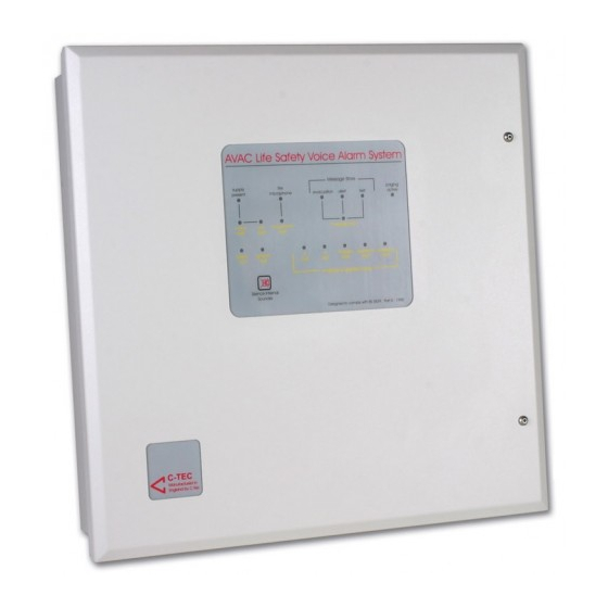
AVAC
- Life Safety Voice Alarm System
Message Store
supply
fire
paging
present
microphone
evacuation
alert
test
active
mains
psu
microphone
message fault
fault
fault
fault
system
general
slave
A
B
standby
speaker A
speaker B
fault
fault
fault
fault
fault
fault
fault
fault
Amplifier & Speaker faults
Silence internal
Sounder
Designed to comply with BS5839 : Part 8 : 1998
& EN 60849 : 1998
www.acornfiresecurity.com
Approved Document No. DAU0000402 Rev 6
Advertisement
Table of Contents

Related Manuals for C-TEC AVAC

Summary of Contents for C-TEC AVAC
- Page 1 AVAC www.acornfiresecurity.com VOICE ALARM SYSTEM AVAC - Life Safety Voice Alarm System Message Store supply fire paging present microphone evacuation alert test active mains microphone message fault fault fault fault system general slave standby speaker A speaker B fault fault...
-
Page 2: Table Of Contents
AVAC connected to an non-Apollo analogue fire alarm loop ....... . -
Page 3: Important Notes
An AVAC master / slave record sheet (DAU0000407) is also provided in the AVAC’s accessory pack. We strongly recommend the relevant side of this sheet (master or slave) is completed by the engineer for future reference. -
Page 4: Short Form Wiring Instructions
SHORT FORM WIRING INSTRUCTIONS AVAC connected to an Apollo analogue fire alarm loop Circled numbers, i.e. refer to the pages you should read for further information P24/25 AVAC Installation and Maintenance Manual • Approved Document No. DAU0000402 Rev 6 • Page 4 www.acornfiresecurity.com... -
Page 5: Avac Connected To An Non-Apollo Analogue Fire Alarm Loop
(Max. 10 slav EOL = End of line de vice AVACs per mast P24/25 P24/25 AVAC Installation and Maintenance Manual • Approved Document No. DAU0000402 Rev 6 • Page 5 www.acornfiresecurity.com... -
Page 6: An Overview Of The Avac Voice Alarm System
The fact that multiple AVACs (and slaves) can be connected to one fire detection system makes the AVAC voice alarm system ideal not just for simple one zone installations but for virtually all small to medium sized applications, including phased evacuation projects, in areas such as hotels, leisure centres and licensed premises. - Page 7 Although Apollo’s analogue protocols do not include a Test state in their output bit configura- tions, some fire detection systems, such as those using a C-TEC XFP fire panel, have a ‘test’ bit pat- tern built into their software. If this is the case, AVAC’s ‘test enable’ facility allows compatible fire detection systems to put the AVAC into test.
- Page 8 ‘a fire has been reported’ and to warn people - if appropriate - not to use the building’s lifts. Amplifier and speaker circuits AVAC is supplied with a minimum of two separate 60 watt Class D amplifiers (A and B). These are designed to drive two loudspeaker circuits, each of which will accommodate up to 60 watts of loudspeaker load, through 100 V line transformers, which step up the voltage for distribution around the site.
-
Page 9: Planning The Wiring
Note that correct cable glanding is essential and due regard should be paid to any system specifications which demand a certain cable type (providing it meets the appropriate national wiring regulations). AVAC Installation and Maintenance Manual • Approved Document No. DAU0000402 Rev 6 • Page 9 www.acornfiresecurity.com... -
Page 10: Mounting Avac
To remove the lid: • Undo the two screws on the right hand side of the AVAC using the Allen key provided. • Hinge the lid 180° to the left and remove the lid earth strap from the base earth connection (take care not to overbend the hinges). - Page 11 80 mm between each of their bases to allow their lids to swing AVAC Installation and Maintenance Manual • Approved Document No. DAU000040 Rev 6 • Page 11 www.acornfiresecurity.com...
-
Page 12: Connecting The Panel
60 watts (not less than 167 Ohms) at 1 kHz. See page 15 for important information on the loading of loudspeaker circuits. DO NOT use a high voltage insulation tester with any electronic devices connected. AVAC Installation and Maintenance Manual • Approved Document No. DAU0000402 Rev 6 • Page 12 www.acornfiresecurity.com... -
Page 13: Mains Wiring And Connection Details
BOARD ≥ 3mm DO NOT attempt to connect mains to the AVAC until you are fully conversant with the layout and features of the power supply PCB, as described below. The power supply PCB combines the functions of a mains to d.c. switched mode power supply unit, battery charging unit and battery monitoring unit. -
Page 14: Standby Battery Connection
21 V approx. If batteries are not fitted, are discharged or in poor condition, a PSU fault will show at the AVAC. Always dispose of used batteries according to the battery manufacturer’s instructions. -
Page 15: Loudspeaker Connection
Loudspeaker circuits AVAC has two loudspeaker outputs, each of which can accommodate up to 60 watts of loudspeaker load. For example 20 loudspeakers tapped at 3 watts or 40 loudspeakers tapped at 1.5 watts. -
Page 16: Calibrating The Loudspeaker, Fire Mic. And Master To Slave Circuits
To store the reference value, the commissioning engineer must activate AVAC’s calibration feature. Note that AVAC’s Fire Mic and Master to Slave circuits will be calibrated at the same time and that prior to calibration the unit will always show a Fire Mic fault. -
Page 17: Fire Alarm Interface Connection
AVAC). When the trigger voltage is removed, the selected message will continue to play. Only when the AVAC’s Reset input is asserted will the system return to normal. When the Reset stimulus is released no message will play unless other inputs are asserted. - Page 18 ISOLATOR Setting AVAC’s unique ID address Use bits 1 to 7 of the eight way DIP switch (SW2) to give AVAC a unique ID address (i.e.13 in the example shown right with test enabled). This can be any address between 1-126 (if group mode is not utilised) or 1-111 (if group mode is utilised (see bottom of page).
-
Page 19: Emergency (Fire) Microphone Connection
If an emergency (fire) microphone is required, you must use a VA405 microphone. Only one VA405 should be used per system. This can be daisychained to up to ten AVAC masters as illus- trated below. Pressing the VA405’s push to talk button will override all other audio signals on the system, including Evacuate and Alert messages, allowing live announcements to be made. -
Page 20: Public Address Paging Connection
Note that if global paging is utilised, the left hand PLK3 link (master/phantom) must be fitted at the last AVAC in the daisychain only. If local paging is used, then the left hand PLK3 link should be fitted at every AVAC (master or slave) which has paging equipment connected directly to it). -
Page 21: Background Music Connection
Any background music source with a balanced line level output (CD player, radio tuner, etc.) can be connected to the AVAC. Background music is AVAC’s lowest priority input and it will play continuously unless there are other audio inputs active on the system. -
Page 22: Class Change Timer Connection
AVAC VOICE ALARM SYSTEM CLASS CHANGE TIMER CONNECTION If required, the AVAC’s BGM input can also be used to provide a ‘class change’ function for schools, colleges, etc. To utilise this feature you will need a TPG5 tone pulse generator with chime and a TU16 programmable seven day, multiple event timer unit. -
Page 23: Slave Avac Wiring
To increase audio coverage in large areas such as warehouses, shopping centres, etc, up to 10 slaves can be connected to one master. For compliance with BS 5939-8, all critical life safety broadcasts made at the AVAC master (i.e. emergency microphone announcements, Evacuate, Alert and Test messages) are automatically passed to the relevant slave(s) for output. -
Page 24: Digital Message Selection
Remove the Evacuate, Alert and/or Test input stimulus. Important: non-latching triggers are not fully compliant with BS 5839-8. However, if the triggers (e.g. loop driven I/O units) are mounted adjacent to AVAC so that they form, in effect, one cabinet, this is normally considered to be acceptable. - Page 25 A fire alarm system is about to be tested. Please take no further action. However, if Function (not Message) Link 4 of the PLK4 option links is fitted, AVAC will also broadcast a “test complete” message when the system is returned to normal, as detailed below:-...
-
Page 26: Fault Indication
AVAC VOICE ALARM SYSTEM FAULT INDICATION When a fault occurs, an intermittent fault buzzer sounds at AVAC and the relevant fault indicator illuminates. The fault relay also activates to report the fault to the fire detection system where, depending on the wiring configuration used, it is usually reported as a sounder fault. - Page 27 If the mains supply has failed and the battery supply has been discharged to the point where the voltage is too low (i.e less than 21 V), AVAC will automatically turn off to avoid damaging the batteries by allowing them to deep discharge. AVAC will not restart unless fresh, fully charged batteries are connected, or the mains supply is restored.
- Page 28 Remove the loudspeaker wiring and connect the EOLD(s) at the AVAC. Press and hold calibrate until the light flashes quickly. If the fault does not clear, check whether the fault is with the EOLDs or the AVAC by swap- ping the EOLDs and recalibrating.
- Page 29 To ascertain if there is an earth fault, open the AVAC and check to see if the Speaker Earth Fault A or B indicators on the main PCB are lit. Amplifier faults occur on the system but when reset they do not reoccur for some con- siderable time.
-
Page 30: Appendix 1 - Loudspeaker Record Sheet
Loudspeaker record sheet This form is provided for you to record the number, type, location and tapping of each loudspeaker on the AVAC’s circuits. On heavily populated systems you may wish to make multiple photocopies of this page before using it. -
Page 31: Appendix 2 - Avac Master And Slave Record Sheets
AVAC master / slave record sheet An AVAC master / slave record sheet (DAU0000407) is provided in the accessory pack supplied. We strongly recommend the relevant side of this sheet (master or slave) is completed by the engineer for future reference. -
Page 32: Technical Specifications
Frequency response .........220 Hz to 6.2 kHz on Page and BGM. AVAC Installation and Maintenance Manual • Approved Document No. DAU0000402 Rev 6 • Page 32...