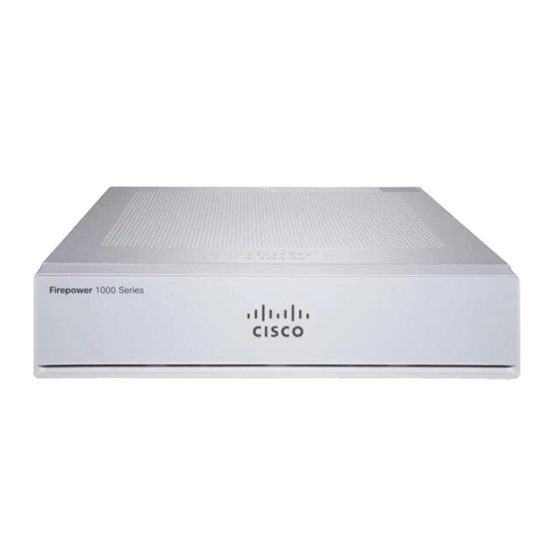
Cisco Firepower 1010 Mount The Chassis
Hide thumbs
Also See for Firepower 1010:
- Getting started manual (182 pages) ,
- Hardware installation manual (40 pages) ,
- Configuration note (21 pages)
Advertisement
Quick Links
Mount the Chassis
•
•
•
•
Unpack and Inspect the Chassis
Note
The chassis is thoroughly inspected before shipment. If any damage occurred during transportation or any
items are missing, contact your customer service representative immediately. Keep the shipping container in
case you need to send the chassis back due to damage.
See
Package Contents
Step 1
Remove the chassis from its cardboard container and save all packaging material.
Step 2
Compare the shipment to the equipment list provided by your customer service representative. Verify that you have all
items.
Step 3
Check for damage and report any discrepancies or damage to your customer service representative. Have the following
information ready:
• Invoice number of shipper (see the packing slip)
• Model and serial number of the damaged unit
• Description of damage
• Effect of damage on the installation
Unpack and Inspect the Chassis, on page 1
Desktop-Mount the Chassis, on page 2
Wall-Mount the Chassis, on page 2
Rack-Mount the Chassis, on page 5
for a list of what shipped with the chassis.
Mount the Chassis
1
Advertisement

Summary of Contents for Cisco Firepower 1010
- Page 1 Mount the Chassis • Unpack and Inspect the Chassis, on page 1 • Desktop-Mount the Chassis, on page 2 • Wall-Mount the Chassis, on page 2 • Rack-Mount the Chassis, on page 5 Unpack and Inspect the Chassis Note The chassis is thoroughly inspected before shipment. If any damage occurred during transportation or any items are missing, contact your customer service representative immediately.
- Page 2 What to do next Install the FIPS Opacity Shield if you need to install a FIPS opacity shield. Install the cables according to your default software configuration as described in the Cisco Firepower 1010 Getting Started Guide. Wall-Mount the Chassis You can purchase an optional wall-mount kit.
- Page 3 Mount the Chassis Wall-Mount the Chassis • Three Phillips M3 x 6 mm screws (part number 48-0460-01) • Two Phillips #6 x 1¼ inch screws (part number 48-2289-01) • One anchor #8 wall screw (part number 51-4718-01) Follow these steps to mount your chassis on a wall. Step 1 Choose an orientation (left-, right-, or rear panel-side up) and a location on the wall for the chassis.
- Page 4 Mount the Chassis Wall-Mount the Chassis Figure 3: Attach the Wall-Mount Bracket to the Chassis Step 4 Use the two #6 x 1¼ inch screws to drill into a stud, or use the anchors (#8 wall screw) from the dry-wall kit to hang it into dry wall.
-
Page 5: Rack-Mount The Chassis
If you are installing a FIPS cover on the chassis, follow the steps in Install the FIPS Opacity Shield. Install the cables according to your default software configuration as described in the Cisco Firepower 1010 Getting Started Guide. Rack-Mount the Chassis... - Page 6 Mount the Chassis Rack-Mount the Chassis Figure 4: Attach the Cable Guides to the Sliding-Rack Tray Flange Two cable guides (part number 700-122664-01) Left cable guide rack tray cutouts Right cable guide rack tray cutouts Six Phillips M3 x 0.5 x 10 mm screws (part number 48-0796-01) a) Align the cable guides with the cutouts on the sliding-rack tray flange (see figure above).
- Page 7 Mount the Chassis Rack-Mount the Chassis Figure 5: Install the Rack Shelf on the Chassis Three short black screws M3 x 6 mm (part number — 48-0384-01) Step 4 Adjust the position of the chassis and the rack shelf until the three mounting holes in the dimples in the bottom of the shelf are aligned with the mounting holes in the bottom of the chassis.
- Page 8 Mount the Chassis Rack-Mount the Chassis Figure 6: Install the Power Supply in the Rack Shelf Velcro straps for power supply Velcro straps for power supply Power supply stop Power supply stop Rear sliding stop and screw (one of two screws on the —...
- Page 9 Mount the Chassis Rack-Mount the Chassis Figure 7: Tighten the Velcro Straps Velcro straps tightened over power supply — Step 8 Slide the rack shelf into the sliding-rack tray. Figure 8: Slide the Rack Shelf into the Sliding-Rack Tray Step 9 The chassis is now installed in the rack shelf, which is installed in the sliding-rack tray.
- Page 10 You can now attach your power supply cord and run it through the cable guides. What to do next Install the cables according to your default software configuration as described in the Cisco Firepower 1010 Getting Started Guide. Mount the Chassis...


