Table of Contents
Advertisement
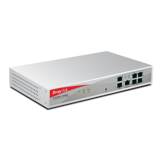
Vigor2950
Security VPN Router
User's Guide
Version: 3.0
Date: 2007/11/23
Copyright 2007 All rights reserved.
This publication contains information that is protected by copyright. No part may be reproduced, transmitted,
transcribed, stored in a retrieval system, or translated into any language without written permission from the copyright
holders. The scope of delivery and other details are subject to change without prior notice.
Microsoft is a registered trademark of Microsoft Corp.
Windows, Windows 95, 98, Me, NT, 2000, XP and Explorer are trademarks of Microsoft Corp.
Apple and Mac OS are registered trademarks of Apple Computer Inc.
Other products may be trademarks or registered trademarks of their respective manufacturers.
Advertisement
Table of Contents

Related Manuals for Draytek Vigor 2950


Summary of Contents for Draytek Vigor 2950
- Page 1 Vigor2950 Security VPN Router User’s Guide Version: 3.0 Date: 2007/11/23 Copyright 2007 All rights reserved. This publication contains information that is protected by copyright. No part may be reproduced, transmitted, transcribed, stored in a retrieval system, or translated into any language without written permission from the copyright holders.
- Page 2 Web registration is preferred. You can register your Vigor router via Owner http://www.draytek.com. Firmware & Tools Due to the continuous evolution of DrayTek technology, all routers will be Updates regularly upgraded. Please consult the DrayTek web site for more information on newest firmware, tools and documents.
-
Page 3: Regulatory Information
Product: Vigor2950 Series Router DrayTek Corp. declares that Vigor2950 Series of routers are in compliance with the following essential requirements and other relevant provisions of R&TTE Directive 1999/5/EEC. The product conforms to the requirements of Electro-Magnetic Compatibility (EMC) Directive 89/336/EEC by complying with the requirements set forth in EN55022/Class A and EN55024/Class A. -
Page 4: Table Of Contents
Preface ...1 1.1 Web Configuration Buttons Explanation ... 1 1.2 LED Indicators and Connectors ... 1 1.2.1 For Vigor2950 ... 2 1.2.2 For Vigor2950G ... 3 1.2.3 For Vigor2950i ... 4 1.2.4 For Vigor2950Gi ... 5 1.3 Hardware Installation ... 6 Configuring Basic Settings ...7 2.1 Changing Password ... - Page 5 3.4.4 DoS Defense ... 55 3.4.5 URL Content Filter ... 58 3.4.6 Web Content Filter... 60 3.5 Objects Settings ... 60 3.5.1 IP Object ... 61 3.5.2 IP Group ... 62 3.5.3 Service Type Object ... 64 3.5.4 Service Type Group... 65 3.5.5 CSM Profile...
- Page 6 3.13 System Maintenance... 147 3.13.1 System Status... 147 3.13.2 TR-069 Setting... 148 3.13.3 Administrator Password... 149 3.13.4 Configuration Backup ... 149 3.13.5 Syslog/Mail Alert ... 151 3.13.6 Time and Date ... 153 3.13.7 Management... 154 3.13.8 Reboot System ... 155 3.13.9 Firmware Upgrade ...
-
Page 7: Preface
The Vigor2950 series router provides Dual-WAN interface (which is a configuration second WAN) for Internet access to make the Internet connection more reliable. The wireless LAN supports more secure features and the transmission speed is up to 108Mbps (SuperG Object-oriented firewall is flexible and allows your network be safe. In addition, through VoIP function, the communication fee for you and remote people can be reduced. -
Page 8: For Vigor2950
ACT (Activity) Monitor LED on Connector (left LED) (right LED) LAN/Monitor (left LED) 1000 (right LED) Interface (Factory Reset) WAN(1/2) LAN/Monitor LAN (1-4) Status Explanation Blinking The router is powered on and running normally. The router is powered off. DMZ Host is specified in certain site. LAN traffic monitor is active. -
Page 9: For Vigor2950G
ACT (Activity) Monitor WLAN LED on Connector (left LED) (right LED) LAN/Monitor (left LED) 1000 (right LED) Interface (Factory Reset) WAN(1/2) LAN/Monitor LAN (1-4) Vigor2950 Series User’s Guide Status Explanation Blinking The router is powered on and running normally. The router is powered off. DMZ Host is specified in certain site. -
Page 10: For Vigor2950I
ACT (Activity) Monitor ISDN LED on Connector (left LED) (right LED) LAN/Monitor (left LED) 1000 (right LED) Interface (Factory Reset) ISDN WAN(1/2) LAN/Monitor LAN (1- 4) Status Explanation Blinking The router is powered on and running normally. The router is powered off. DMZ Host is specified in certain site. -
Page 11: For Vigor2950Gi
ACT (Activity) Monitor WLAN ISDN LED on Connector (left LED) (right LED) LAN/Monitor (left LED) 1000 (right LED) Interface (Factory Reset) ISDN WAN(1/2) LAN/Monitor LAN (1- 4) Vigor2950 Series User’s Guide Status Explanation Blinking The router is powered on and running normally. The router is powered off. -
Page 12: Hardware Installation
Before starting to configure the router, you have to connect your devices correctly. Connect the power cord to the router’s power port on the rear panel, and the other side into a wall outlet. Power on the device by pressing down the power switch on the rear panel. The system starts to initiate. -
Page 13: Configuring Basic Settings
For use the router properly, it is necessary for you to change the password of web configuration for security and adjust primary basic settings. This chapter explains how to setup a password for an administrator and how to adjust basic settings for accessing Internet successfully. - Page 14 Go to System Maintenance page and choose Administrator Password. Enter the login password (the default is blank) on the field of Old Password. Type a new one in the field of New Password and retype it on the field of Retype New Password.
-
Page 15: Quick Start Wizard
If your router can be under an environment with high speed NAT, the configuration provide here can help you to deploy and use the router quickly. The first screen of Quick Start Wizard is entering login password. After typing the password, please click Next. On the next page as shown below, please select the WAN interface that you use. -
Page 16: Pppoe
In the Quick Start Wizard, you can configure the router to access the Internet with different protocol/modes such as PPPoE, PPTP, L2TP, Static IP or DHCP. The router supports the DSL WAN interface for Internet access. PPPoE stands for Point-to-Point Protocol over Ethernet. It relies on two widely accepted standards: PPP and Ethernet. - Page 17 Password Confirm Password Click Next for viewing summary of such connection. Click Finish. A page of Quick Start Wizard Setup OK!!! will appear. Then, the system status of this protocol will be shown. Vigor2950 Series User’s Guide Assign a valid password provided by the ISP. Retype the password to confirm it.
-
Page 18: Pptp
Click PPTP as the protocol. Type in all the information that your ISP provides for this protocol. Click Next for viewing summary of such connection. Click Finish. A page of Quick Start Wizard Setup OK!!! will appear. Then, the system status of this protocol will be shown. -
Page 19: L2Tp
Click L2TP as the protocol. Type in all the information that your ISP provides for this protocol. After finishing the settings in this page, click Next to see the following page. Vigor2950 Series User’s Guide... -
Page 20: Static Ip
Click Static IP as the protocol. Type in all the information that your ISP provides for this protocol. After finishing the settings in this page, click Next to see the following page. Click Finish. A page of Quick Start Wizard Setup OK!!! will appear. Then, the system status of this protocol will be shown. -
Page 21: Dhcp
Click DHCP as the protocol. Type in all the information that your ISP provides for this protocol. After finishing the settings in this page, click Next to see the following page. Click Finish. A page of Quick Start Wizard Setup OK!!! will appear. Then, the system status of this protocol will be shown. -
Page 22: Online Status (重抓 Vivian)
The online status shows the system status, WAN status, ADSL Information and other status related to this router within one page. If you select PPPoE/PPTP as the protocol, you will find out a link of Dial PPPoE/PPPoA or Drop PPPoE/PPPoA in the Online Status web page. - Page 23 Online status for DHCP Detailed explanation is shown below: Primary DNS Secondary DNS LAN Status IP Address TX Packets RX Packets WAN1/2 Status Line Name Mode Up Time GW IP TX Packets TX Rate RX Packets RX Rate ISDN Status Channel Active Conn.
-
Page 24: Saving Configuration
Dial ISDN Drop B1/B2 Note: The words in green mean that the WAN connection of that interface (WAN1/WAN2) is ready for accessing Internet; the words in red mean that the WAN connection of that interface (WAN1/WAN2) is not ready for accessing Internet. -
Page 25: Advanced Web Configuration
After finished basic configuration of the router, you can access Internet with ease. For the people who want to adjust more setting for suiting his/her request, please refer to this chapter for getting detailed information about the advanced configuration of this router. As for other examples of application, please refer to chapter 4. -
Page 26: General Setup
Below shows the menu items for Internet Access. This section will introduce some general settings of Internet and explain the connection modes for WAN1 and WAN2 in details. This router supports dual WAN function. It allows users to access Internet and combine the bandwidth of the dual WAN to speed up the transmission through the network. - Page 27 Physical Type Load Balance Mode Line Speed Active Mode Vigor2950 Series User’s Guide You can change the physical type for WAN2 or choose Auto negotiation for determined by the system. If you know the practical bandwidth for your WAN interface, please choose the setting of According to Line Speed.
-
Page 28: Internet Access
For the router supports dual WAN function, the users can set different WAN settings (for WAN1/WAN2) for Internet Access. Due to different physical mode for WAN1 and WAN2, the Access Mode for these two connections also varies slightly. Index Display Name Physical Mode Access Mode Details Page... - Page 29 To use PPPoE as the accessing protocol of the internet, please choose Internet Access from WAN menu. Then, select PPPoE mode for WAN2. The following web page will be shown. PPPoE Client Mode ISP Access Setup ISDN Dial Backup Setup WAN Connection Detection Vigor2950 Series User’s Guide...
- Page 30 PPP/MP Setup IP Address Assignment Method (IPCP) After finishing all the settings here, please click OK to activate them. For static IP mode, you usually receive a fixed public IP address or a public subnet, namely multiple public IP addresses from your DSL or Cable ISP service providers. In most cases, a Cable service provider will offer a fixed public IP, while a DSL service provider will offer a public subnet.
- Page 31 To use Static or Dynamic IP as the accessing protocol of the internet, please choose Internet Access from WAN menu. Then, select Static or Dynamic IP mode for WAN2. The following web page will be shown. Static or Dynamic IP (DHCP Client) ISDN Dial Backup Setup...
- Page 32 RIP Protocol WAN IP Network Settings DNS Server IP Address TTL (Time to Live) – Displays value for your reference. TTL value is set by telnet command. Routing Information Protocol is abbreviated as RIP(RFC1058) specifying how routers exchange routing tables information. Click Enable RIP for activating this function.
- Page 33 To use PPTP/L2TP as the accessing protocol of the internet, please choose Internet Access from WAN menu. Then, select PPTP/L2TP mode for WAN2/WAN2. The following web page will be shown. PPTP/L2TP Client Mode ISP Access Setup ISDN Dial Backup Setup PPP Setup Vigor2950 Series User’s Guide Click Enable PPTP to enable a PPTP client to establish a tunnel...
-
Page 34: Load-Balance Policy
IP Address Assignment Method(IPCP) WAN IP Network Settings only when the Active on demand option for Active Mode is selected in WAN>> General Setup page. Fixed IP - Usually ISP dynamically assigns IP address to you each time you connect to it and request. In some case, your ISP provides service to always assign you the same IP address whenever you request. - Page 35 This router supports the function of load balancing. It can assign traffic with protocol type, IP address for specific host, a subnet of hosts, and port range to be allocated in WAN1 or WAN2 interface. The user can assign traffic category and force it to go to dedicate network interface based on the following web page setup.
- Page 36 Enable Protocol Binding WAN interface Src IP Start Src IP End Dest IP Start Dest IP End Dest Port Start Dest Port End Check this box to enable this policy. Use the drop-down menu to choose a proper protocol for the WAN interface.
-
Page 37: Lan
Local Area Network (LAN) is a group of subnets regulated and ruled by router. The design of network structure is related to what type of public IP addresses coming from your ISP. The most generic function of Vigor router is NAT. It creates a private subnet of your own. As mentioned previously, the router will talk to other public hosts on the Internet by using public IP address and talking to local hosts by using its private IP address. - Page 38 Vigor router will exchange routing information with neighboring routers using the RIP to accomplish IP routing. This allows users to change the information of the router such as IP address and the routers will automatically inform for each other. When you have several subnets in your LAN, sometimes a more effective and quicker way for connection is the Static routes function rather than other method.
-
Page 39: General Setup
This page provides you the general settings for LAN. Click LAN to open the LAN settings page and choose General Setup. 1st IP Address 1st Subnet Mask For IP Routing Usage Click Enable to invoke this function. The default setting is IP Address Subnet Mask DHCP Server... - Page 40 RIP Protocol Control DHCP Server Configuration Start IP Address: Enter a value of the IP address pool for the DHCP server to start with when issuing IP addresses. If the 2nd IP address of your router is 220.135.240.1, the starting IP address must be 220.135.240.2 or greater, but smaller than 220.135.240.254.
-
Page 41: Static Route
DNS Server Configuration There are two common scenarios of LAN settings that stated in Chapter 4. For the configuration examples, please refer to that chapter to get more information for your necessity. Go to LAN to open setting page and choose Static Route. Vigor2950 Series User’s Guide of the router, which means the router is the default gateway. - Page 42 Index Destination Address Status Viewing Routing Table Displays the routing table for your reference. Here is an example of setting Static Route in Main Router so that user A and B locating in different subnet can talk to each other via the router. Assuming the Internet access has been configured and the router works properly: use the Main Router to surf the Internet.
- Page 43 Note: There are two reasons that we have to apply RIP Protocol Control on 1st Subnet. The first is that the LAN interface can exchange RIP packets with the neighboring routers via the 1st subnet (192.168.1.0/24). The second is that those hosts on the internal private subnets (ex. 192.168.10.0/24) can access the Internet via the router, and continuously exchange of IP routing information with different subnets.
-
Page 44: Bind Ip To Mac
This function is used to bind the IP and MAC address in LAN to have a strengthen control in network. When this function is enabled, all the assigned IP and MAC address binding together cannot be changed. If you modified the binding IP or MAC address, it might cause you not access into the Internet. -
Page 45: Nat
Edit Delete Note: Before you select Strict Bind, you have to bind one set of IP/MAC address for one PC. If not, no one of the PCs can access into Internet. And the web configurator of the router might not be accessed. Usually, the router serves as an NAT (Network Address Translation) router. -
Page 46: Port Redirection
Port Redirection is usually set up for server related service inside the local network (LAN), such as web servers, FTP servers, E-mail servers etc. Most of the case, you need a public IP address for each server and this public IP address/domain name are recognized by all users. Since the server is actually located inside the LAN, the network well protected by NAT of the router, and identified by its private IP address/port, the goal of Port Redirection function is to forward all access request with public IP address from external users to the mapping... -
Page 47: Dmz Host
Mode Service Name Protocol Public Port Private IP Private Port Active Note that the router has its own built-in services (servers) such as Telnet, HTTP and FTP etc. Since the common port numbers of these services (servers) are all the same, you may need to reset the router in order to avoid confliction. - Page 48 As mentioned above, Port Redirection can redirect incoming TCP/UDP or other traffic on particular ports to the specific private IP address/port of host in the LAN. However, other IP protocols, for example Protocols 50 (ESP) and 51 (AH), do not travel on a fixed port. Vigor router provides a facility DMZ Host that maps ALL unsolicited data on any protocol to a single host in the LAN.
- Page 49 Enable Private IP Choose PC Vigor2950 Series User’s Guide Check to enable the DMZ Host function. Enter the private IP address of the DMZ host, or click Choose PC to select one. Click this button and then a window will automatically pop up, as depicted below.
-
Page 50: Open Ports
Open Ports allows you to open a range of ports for the traffic of special applications. Common application of Open Ports includes P2P application (e.g., BT, KaZaA, Gnutella, WinMX, eMule and others), Internet Camera etc. Ensure that you keep the application involved up-to-date to avoid falling victim to any security exploits. - Page 51 Enable Open Ports Comment WAN Interface WAN IP Local Computer Choose PC Protocol Start Port End Port Vigor2950 Series User’s Guide Check to enable this entry. Make a name for the defined network application/service. Specify the WAN interface that will be used for this entry. Such drop down list will be shown only if you have entered other WAN IP address in WAN IP Alias window.
-
Page 52: Firewall
While the broadband users demand more bandwidth for multimedia, interactive applications, or distance learning, security has been always the most concerned. The firewall of the Vigor router helps to protect your local network against attack from unauthorized outsiders. It also restricts users in the local network from accessing the Internet. - Page 53 Depending on whether there is an existing Internet connection, or in other words “the WAN link status is up or down”, the IP filter architecture categorizes traffic into two: Call Filter and Data Filter. Call Filter - When there is no existing Internet connection, Call Filter is applied to all traffic, all of which should be outgoing.
- Page 54 As the popularity of all kinds of instant messenger application arises, communication cannot become much easier. Nevertheless, while some industry may leverage this as a great tool to connect with their customers, some industry may take reserve attitude in order to reduce employee misusage during office hour or prevent unknown security leak.
-
Page 55: General Setup
We all know that the content on the Internet just like other types of media may be inappropriate sometimes. As a responsible parent or employer, you should protect those in your trust against the hazards. With Web filtering service of the Vigor router, you can protect your business from common primary threats, such as productivity, legal liability, network and security threats. -
Page 56: Filter Setup
Select Pass or Block for the packets that do not match with the filter rules. For troubleshooting needs you can specify the filter log and/or CSM log here by checking the box. The log will be displayed on Draytek Syslog window. Select a CSM profile for global IM/P2P application blocking. All the hosts in LAN must follow the standard configured in the CSM profile selected here. - Page 57 Filter Rule Active Comment Move Up/Down Next Filter Set To edit Filter Rule, click the Filter Rule index button to enter the Filter Rule setup page. Check to enable the Filter Rule Comments Index(1-15) Direction Source/Destination IP Click Edit to access into the following dialog to choose the Vigor2950 Series User’s Guide Click a button numbered (1 ~ 7) to edit the filter rule.
- Page 58 To set the IP address manually, please choose Any Address/Single Address/Range Address/Subnet Address as the Address Type and type them in this dialog. In addition, if you want to use the IP range from defined groups or objects, please choose Group and Objects as the Address Type.
- Page 59 CSM profile setup. For troubleshooting needs you can specify the filter log and/or CSM log here. Check the corresponding box to enable the log function. Then, the filter log and/or CSM log will be shown on Draytek Syslog window. it indicates all...
- Page 60 As stated before, all the traffic will be separated and arbitrated using on of two IP filters: call filter or data filter. You may preset 12 call filters and data filters in Filter Setup and even link them in a serial manner. Each filter set is composed by 7 filter rules, which can be further defined.
-
Page 61: Dos Defense
As a sub-functionality of IP Filter/Firewall, there are 15 types of detect/ defense function in the DoS Defense setup. The DoS Defense functionality is disabled for default. Click Firewall and click DoS Defense to open the setup page. Enable Dos Defense Enable SYN flood defense Enable UDP flood... - Page 62 Block IP options Block Land Block Smurf Block trace router Block SYN fragment Block Fraggle Attack Block TCP flag scan Block Tear Drop Block Ping of Death Block ICMP Fragment Check the box to activate the Block ICMP fragment function. Any Block Land port-scanning Threshold rate, the Vigor router will send out a warning.
- Page 63 Block Unknown Protocol Warning Messages Vigor2950 Series User’s Guide SYN packets with the identical source and destination addresses, as well as the port number to victims. Check the box to activate the Block Unknown Protocol function. Individual IP packet has a protocol field in the datagram header to indicate the protocol type running over the upper layer.
-
Page 64: Url Content Filter
Based on the list of user defined keywords, the URL Content Filter facility in Vigor router inspects the URL string in every outgoing HTTP request. No matter the URL string is found full or partial matched with a keyword, the Vigor router will block the associated HTTP connection. - Page 65 Prevent web access from IP address Enable Restrict Web Feature Enable Excepting Subnets Time Schedule Vigor2950 Series User’s Guide decline the connection request to the website whose URL string matched to any user-defined keyword. It should be noticed that the more simplified the blocking keyword list, the more efficiently the Vigor router perform.
-
Page 66: Web Content Filter
Click Firewall and click Web Content Filter to open the setup page. For this section, please refer to Web Content Filter user’s guide. For IPs in a range and service ports in a limited range usually will be applied in configuring router’s settings, therefore we can define them with objects and bind them with groups for using conveniently. -
Page 67: Ip Object
You can set up to 192 sets of IP Objects with different conditions. Set to Factory Default Click the number under Index column for settings in detail. Name Interface Address Type Vigor2950 Series User’s Guide Clear all profiles. Type a name for this profile. Maximum 15 characters are allowed. -
Page 68: Ip Group
Start IP Address End IP Address Subnet Mask Invert Select Below is an example of IP objects settings. This page allows you to bind several IP objects into one IP group. Set to Factory Default Click the number under Index column for settings in detail. only. - Page 69 Name Interface Available IP Objects Selected IP Objects Vigor2950 Series User’s Guide Type a name for this profile. Maximum 15 characters are allowed. Choose WAN, LAN or Any to display all the available IP objects with the specified interface. All the available IP objects with the specified interface chosen above will be shown in this box.
-
Page 70: Service Type Object
You can set up to 96 sets of Service Type Objects with different conditions. Set to Factory Default Click the number under Index column for settings in detail. Name Protocol Source/Destination Port Clear all profiles. Type a name for this profile. Specify the protocol(s) which this profile will apply to. -
Page 71: Service Type Group
Below is an example of service type objects settings. This page allows you to bind several service types into one group. Set to Factory Default Click the number under Index column for settings in detail. Vigor2950 Series User’s Guide (!=) – when the first and last value are the same, all the ports except the port defined here;... -
Page 72: Csm Profile
Name Available Service Type Objects Selected Service Type Objects You can define policy profiles for different policy of IM (Instant Messenger)/P2P (Peer to Peer) application. CSM profile can be used in Filter Setup page. Set to Factory Default Click the number under Index column for settings in detail. Type a name for this profile. -
Page 73: Bandwidth Management
Profile Name There are several items for IM, VoIP, P2P provided here for you to choose to disallow people using. Simple check the box (es) and then click OK. Later, in the Firewall>>Edit Filter Set>>Edit Filter Rule page, you can use Content Management drop down list to choose the proper CSM profile as the standard for the host(s) to follow. - Page 74 To activate the function of limit session, simply click Enable and set the default session limit. Enable Disable Default session limit Limitation List Start IP End IP Maximum Sessions Edit Delete Index (1-15) in Schedule Setup Click this button to activate the function of limit session. Click this button to close the function of limit session.
-
Page 75: Bandwidth Limit
The downstream or upstream from FTP, HTTP or some P2P applications will occupy large of bandwidth and affect the applications for other programs. Please use Limit Bandwidth to make the bandwidth usage more efficient. In the Bandwidth Management menu, click Bandwidth Limit to open the web page. To activate the function of limit bandwidth, simply click Enable and set the default upstream and downstream limit. -
Page 76: Quality Of Service
Delete Index (1-15) in Schedule Setup Deploying QoS (Quality of Service) management to guarantee that all applications receive the service levels required and sufficient bandwidth to meet performance expectations is indeed one important aspect of modern enterprise network. One reason for QoS is that numerous TCP-based applications tend to continually increase their transmission rate and consume all available bandwidth, which is called TCP slow start. - Page 77 However, each node may take different attitude toward packets with high priority marking since it may bind with the business deal of SLA among different DS domain owners. It’s not easy to achieve deterministic and consistent high-priority QoS traffic throughout the whole network with merely Vigor router’s effort.
- Page 78 Enable the QoS Control WAN Inbound Bandwidth It allows you to set the connecting rate of data input for WAN. WAN Outbound Bandwidth It allows you to set the connecting rate of data output for Reserved Bandwidth Ratio It is reserved for the group index in the form of ratio of Enable UDP Bandwidth Control Limited_bandwidth Ratio...
- Page 79 The first three (Class 1 to Class 3) class rules can be adjusted for your necessity. To add, edit or delete the class rule, please click the Edit link of that one. After you click the Edit link, you will see the following page. Now you can define the name for that Class.
- Page 80 For adding a new rule, click Add to open the following page. Local Address Remote Address Edit DiffServ CodePoint Service Type By the way, you can set up to 20 rules for one Class. If you want to edit an existed rule, please select the radio button of that one and click Edit to open the rule edit page for modification.
- Page 81 To add a new service type, edit or delete an existed service type, please click the Edit link under Service Type field. After you click the Edit link, you will see the following page. For adding a new service type, click Add to open the following page. Vigor2950 Series User’s Guide...
- Page 82 Service Name Service Type Port Configuration By the way, you can set up to 40 service types. If you want to edit/delete an existed service type, please select the radio button of that one and click Edit/Edit for modification. Type in a new service for your request. Choose the type (TCP, UDP or TCP/UDP) for the new service.
-
Page 83: Applications
Below shows the menu items for Applications. The ISP often provides you with a dynamic IP address when you connect to the Internet via your ISP. It means that the public IP address assigned to your router changes each time you access the Internet. - Page 84 Domain Name Active View Log Force Update Select Index number 1 to add an account for the router. Check Enable Dynamic DNS Account, and choose correct Service Provider: dyndns.org, type the registered hostname: hostname and domain name suffix: dyndns.org in the Domain Name block. The following two blocks should be typed your account Login Name: test and Password: test.
-
Page 85: Schedule
In the DDNS setup menu, click the Index number you want to delete and then push Clear All button to delete the account. The Vigor router has a built-in real time clock which can update itself manually or automatically by means of Network Time Protocols (NTP). As a result, you can not only schedule the router to dialup to the Internet at a specified time, but also restrict Internet access to certain hours so that users can connect to the Internet only during certain hours, say, business hours. - Page 86 Enable Schedule Setup Start Date (yyyy-mm-dd) Start Time (hh:mm) Duration Time (hh:mm) Action Idle Timeout Example Suppose you want to control the PPPoE Internet access connection to be always on (Force On) from 9:00 to 18:00 for whole week. Other time the Internet access connection should be disconnected (Force Down).
-
Page 87: Radius
Configure the Force Down from 18:00 to next day 9:00 for whole week. Assign these two profiles to the PPPoE Internet access profile. Now, the PPPoE Internet connection will follow the schedule order to perform Force On or Force Down action according to the time plan that has been pre-defined in the schedule profiles. -
Page 88: Upnp
The UPnP (Universal Plug and Play) protocol is supported to bring to network connected devices the ease of installation and configuration which is already available for directly connected PC peripherals with the existing Windows 'Plug and Play' system. For NAT routers, the major feature of UPnP on the router is “NAT Traversal”. -
Page 89: Wake On Lan
The reminder as regards concern about Firewall and UPnP Can't work with Firewall Software Enabling firewall applications on your PC may cause the UPnP function not working properly. This is because these applications will block the accessing ability of some network ports. Security Considerations Activating the UPnP function on your network may incur some security threats. - Page 90 Wake by IP Address MAC Address Wake Up Two types provide for you to wake up the binded IP. If you choose Wake by MAC Address, you have to type the correct MAC address of the host in MAC Address boxes. If you choose Wake by IP Address, you have to choose the correct IP address.
-
Page 91: Vpn And Remote Access
A Virtual Private Network (VPN) is the extension of a private network that encompasses links across shared or public networks like the Internet. In short, by VPN technology, you can send data between two computers across a shared or public network in a manner that emulates the properties of a point-to-point private link. - Page 92 Dial-In PPP Authentication PAP Only PAP or CHAP Dial-In PPP Encryption (MPPE Optional MPPE Mutual Authentication (PAP) Start IP Address Select this option to force the router to authenticate dial-in users with the PAP protocol. Selecting this option means the router will attempt to authenticate dial-in users with the CHAP protocol first.
-
Page 93: Ipsec General Setup
In IPSec General Setup, there are two major parts of configuration. There are two phases of IPSec. Phase 1: negotiation of IKE parameters including encryption, hash, Diffie-Hellman parameter values, and lifetime to protect the following IKE exchange, authentication of both peers using either a Pre-Shared Key or Digital Signature (x.509). The peer that starts the negotiation proposes all its policies to the remote peer and then remote peer tries to find a highest-priority match with its policies. -
Page 94: Ipsec Peer Identity
To use digital certificate for peer authentication in either LAN-to-LAN connection or Remote User Dial-In connection, here you may edit a table of peer certificate for selection. As shown below, the router provides 200 entries of digital certificates for peer dial-in users. Set to Factory Default Index Name... - Page 95 Profile Name Accept Any Peer ID Accept Subject Alternative Name Accept Subject Name Vigor2950 Series User’s Guide Type in a name in this file. Click to accept any peer regardless of its identity. Click to check one specific field of digital signature to accept the peer with matching value.
-
Page 96: Remote Dial-In User
You can manage remote access by maintaining a table of remote user profile, so that users can be authenticated to dial-in via ISDN or build the VPN connection. You may set parameters including specified connection peer ID, connection type (ISDN Dial-In connection, VPN connection - including PPTP, IPSec Tunnel, and L2TP by itself or over IPSec) and corresponding security methods, etc. - Page 97 Enable this account ISDN PPTP IPSec Tunnel L2TP Specify Remote Node Vigor2950 Series User’s Guide Check the box to enable this function. Idle Timeout- If the dial-in user is idle over the limitation of the timer, the router will drop this connection. By default, the Idle Timeout is set to 300 seconds.
- Page 98 Netbios Naming Packet User Name Password IKE Authentication Method This group of fields is applicable for IPSec Tunnels and L2TP IPSec Security Method Callback Function select above will apply the authentication methods and security methods in the general settings. Pass – click it to have an inquiry for data transmission between the hosts located on both sides of VPN Tunnel while connecting.
-
Page 99: Lan To Lan
Here you can manage LAN-to-LAN connections by maintaining a table of connection profiles. You may set parameters including specified connection direction (dial-in or dial-out), connection peer ID, connection type (ISDN connection, VPN connection - including PPTP, IPSec Tunnel, and L2TP by itself or over IPSec) and corresponding security methods, etc. - Page 100 Profile Name Enable this profile VPN Connection Through Use the drop down menu to choose a proper WAN interface Netbios Naming Packet Specify a name for the profile of the LAN-to-LAN connection. Check here to activate this profile. for this profile. This setting is useful for dial-out only. WAN1 First - While connecting, the router will use WAN1 as the first channel for VPN connection.
- Page 101 Call Direction Always On or Idle Timeout Always On-Check to enable router always keep VPN Enable PING to keep alive This function is to help the router to determine the status of PING to the IP ISDN PPTP IPSec Tunnel L2TP with …...
- Page 102 Password PPP Authentication VJ compression IKE Authentication Method IPSec Security Method Medium Advanced This field is applicable when you select ISDN, PPTP or L2TP with or without IPSec policy above. This field is applicable when you select ISDN, PPTP or L2TP with or without IPSec policy above.
- Page 103 IKE phase 1 mode -Select from Main mode and Aggressive mode. The ultimate outcome is to exchange security proposals to create a protected secure channel. Main mode is more secure than Aggressive mode since more exchanges are done in a secure channel to set up the IPSec session. However, the Aggressive mode is faster.
- Page 104 Callback Function (for i models only) algorithms. IKE phase 1 key lifetime-For security reason, the lifetime of key should be defined. The default value is 28800 seconds. You may specify a value in between 900 and 86400 seconds. IKE phase 2 key lifetime-For security reason, the lifetime of key should be defined.
- Page 105 Allowed Dial-In Type Determine the dial-in connection with different types. ISDN - Allow the remote ISDN LAN-to-LAN connection. You should set the User Name and Password of remote dial-in user below. This feature is useful for i model only. In addition, you can further set up Callback function below.
- Page 106 User Name Password VJ Compression IKE Authentication Method IPSec Security Method Callback Function (CPCB) The callback function provides a callback service only for the becomes one pure L2TP connection. Must- Specify the IPSec policy to be definitely applied on the L2TP connection.
- Page 107 GRE over IPSec Settings TCP/IP Network Settings Vigor2950 Series User’s Guide automatically. Please specify the time budget for the dial-in user. The budget will be decreased automatically per callback connection. The default value 0 means no limitation of callback period. Enable IPSec Dial-Out function GRE over IPSec: Check this box to verify data and transmit data in encryption with GRE over IPSec packet after configuring IPSec Dial-Out...
-
Page 108: Vpn Trunk Management
VPN trunk includes four features - VPN Backup, VPN load balance, GRE over IPSec, and Binding tunnel policy. VPN TRUNK Management is a backup mechanism which can set multiple VPN tunnels as backup tunnel. It can assure the network connection not tobe cut off due to network environment blocked by any reason. - Page 109 Specific ERD (Environment Recovery Detection) mechanism which can be operated by using Telnet command PN TRUNK-VPN Backup mechanism of single VPN tunnel is off-line. Before setting VPN TRUNK backup profile, please configure at least two sets of LAN-to-LAN profiles (with fully configured dial-out settings) first, otherwise you will not have selections for grouping Member1 and Member2.
- Page 110 Backup Profile List Set to Factory Default - Click to clear all VPN TRUNK-VPN Backup mechanism profile. No -The order of VPN TRUNK-VPN Backup mechanism profile. Status (on Backup Profile field) - “v” means such profile is enabled; ”x” means such profile is disabled. Name (on Backup Profile field) - Display the name of VPN TRUNK-VPN Backup mechanism profile.
- Page 111 Detailed information for this dialog, see later section - Advanced Load Balance and Backup. Load Balance Profile List Set to Factory Default - Click to clear all VPN TRUNK-VPN Load Balance mechanism profile. No - The order of VPN TRUNK-VPN Load Balance mechanism profile.
- Page 112 General Setup Edit Detailed information for this dialog, see later section - Advanced Load Balance and Backup. Status- After choosing one of the profile listed above, please click Enable to activate this profile. If you click Disable, the selected or current used VPN TRUNK-Backup/Load Balance mechanism profile will not have any effect for VPN tunnel.
- Page 113 Delete VPN TRUNK – VPN Backup mechanism will be activated automatically after the initial connection of single VPN Tunnel off-line. The content in Member1/2 within VPN TRUNK – VPN Backup mechanism backup profile is similar to dial-out profile configured in LAN-to-LAN web page. VPN TRUNK – VPN Backup mechanism backup profile will process and handle everything unless it is off-line once it is activated.
- Page 114 expressed in black. Please go to LAN to LAN to set a profile with IPSec. If the router will be used as the VPN Server (i.e., with virtual address 192.168.50.200). Please type 192.168.50.200 in the field of My GRE IP. Type IP address (192.168.50.100) of the client in the field of Peer GRE IP.
- Page 115 After setting profiles for load balance, you can choose any one of them and click Advance for more detailed configuration. The windows for advanced load balance and backup are different. Refer to the following explanation: Advanced Load Balance Profile Name Load Balance Algorithm VPN Load Balance –...
- Page 116 binding tunnel table. Tunnel Bind Table Index- 400 binding tunnel tables are provided by this device. Choose any one of them for such Load Balance profile. Active – In-active/DeleteActive can delete this binding tunnel table. Active can activate this binding tunnel table. Binding Dial Out Index –...
- Page 117 Detail Information Advanced Backup Profile Name ERD Mode Vigor2950 Series User’s Guide This field will display detailed information for Binding Tunnel Policy. Below shows a successful binding tunnel policy for load balance: Note : To configure a successful binding tunnel, you have to: A.
- Page 118 periodically and type the value for it (the unit is second). If VPN server for Member 1 has completed the network connection, current VPN Tunnel backup connection will be off. Resume – when VPN connection breaks down or disconnects, Member 1 will be the top priority for the system to do VPN connection.
-
Page 119: Connection Management
You can find the summary table of all VPN connections. You may disconnect any VPN connection by clicking Drop button. You may also aggressively Dial-out by using Dial-out Tool and clicking Dial button. it will be listed in Backup/Load Balance Mode drop-down list dialing. - Page 120 Dial Refresh Seconds Refresh VPN Load Balance function. Click this button to execute dial out function under General Mode, Backup Mode or Load Balance Mode. Choose the time for refresh the dial information among 5, 10, and 30. Click this button to refresh the whole connection status. Vigor2950 Series User’s Guide...
-
Page 121: Certificate Management
A digital certificate works as an electronic ID, which is issued by a certification authority (CA). It contains information such as your name, a serial number, expiration dates etc., and the digital signature of the certificate-issuing authority so that a recipient can verify that the certificate is real. - Page 122 Import Refresh View After clicking Generate, the generated information will be displayed on the window below: Type in all the information that the window request. Then click Generate again. Click this button to import a saved file as the certification information.
-
Page 123: Trusted Ca Certificate
Trusted CA certificate lists three sets of trusted CA certificate. To import a pre-saved trusted CA certificate, please click IMPORT to open the following window. Use Browse… to find out the saved text file. Then click Import. The one you imported will be listed on the Trusted CA Certificate window. -
Page 124: Certificate Backup
Local certificate and Trusted CA certificate for this router can be saved within one file. Please click Backup on the following screen to save them. If you want to set encryption password for these certificates, please type characters in both fields of Encrypt password and Retype password. -
Page 125: General Settings
This web page allows you to enable wireless LAN function. ISDN Port Country Code Own Number MSN Numbers for the Router Blocked MSN Numbers for the router Vigor2950 Series User’s Guide Click Enable to open the ISDN port and Disable to close it. For proper operation on your local ISDN network, you should choose the correct country code. -
Page 126: Dial To Single/Dual Isps
Select Dialing to a Single ISP if you access the Internet via a single ISP. ISP Access Setup PPP/MP Setup ISP Name - Enter your ISP name such as Seednet, Hinet and so on. Dial Number -Enter the ISDN access number provided by your ISP. - Page 127 IP Address Assignment Method (IPCP) Select Dialing to Dual ISPs if you have more than one ISP. You will be able to dial to both ISPs at the same time. This is mainly for those ISPs that do not support Multiple-Link PPP (ML-PPP).
- Page 128 Primary ISP Setup IP Address Assignment Method (IPCP) for primary ISP setup Secondary ISP Setup) IP Address Assignment Method (IPCP) for secondary ISP setup After entering the necessary settings and clicking OK, you will see Goto ISDN Diagnostic link appears on the bottom of the webpage. To have an ISDN connection, please click this link.
-
Page 129: Virtual Ta
Virtual TA means the local hosts or PCs in the network that uses popular CAPI-based software such as RVS-COM or BVRP to access the router as a local ISDN TA for sending or receiving FAX messages over the ISDN line. Basically, it is a client/server network model. The built-in Virtual TA server handles the establishment and release of connections. - Page 130 One ISDN BRI interface has two B channels. The maximum number of active clients is also 2. Before you configure the Virtual TA, you must set the correct country code in ISDN Setup. Virtual TA Server Virtual TA User Profiles Insert the CD-ROM bundled with your Vigor router.
- Page 131 On the server - Click Virtual TA (Remote CAPI) Setup link, and fill in the Username and Password fields. Check the Active box to enable the account. On the client - Right-click the mouse on the VT icon. The following pop-up menu will be shown.
-
Page 132: Call Control
Type the specified MSN number in the CAPI-based software. When the Virtual TA server sends an alert signal to the specified Virtual TA client, the CAPI-based software will also receive the action, the software will not accept the incoming call. Some applications require that the router (only for the ISDN models) be remotely activated, or be able to dial up to the ISP via the ISDN interface. - Page 133 Basic Setup Bandwidth-On-Demand (BOD) Setup Vigor2950 Series User’s Guide Note that Dialing to a Single ISP should be pre-configured properly. Link Type - Because ISDN has two B channels (64Kbps/per channel), you can specify whether you would like to have single B channel, two B channels or BOD (Bandwidth on Demand).
-
Page 134: Wireless Lan
This function is used for G models only. Over recent years, the market for wireless communications has enjoyed tremendous growth. Wireless technology now reaches or is capable of reaching virtually every location on the surface of the earth. Hundreds of millions of people exchange information every day via wireless communication products. - Page 135 WEP (Wired Equivalent Privacy) is a legacy method to encrypt each frame transmitted via radio using either a 64-bit or 128-bit key. Usually access point will preset a set of four keys and it will communicate with each station using only one out of the four keys. WPA(Wi-Fi Protected Access), the most dominating security mechanism in industry, is separated into two categories: WPA-personal or called WPA Pre-Share Key (WPA/PSK), and WPA-Enterprise or called WPA/802.1x.
- Page 136 Example 3 Separate the Wireless and the Wired LAN- WLAN Isolation enables you to isolate your wireless LAN from wired LAN for either quarantine or limit access reasons. To isolate means neither of the parties can access each other. To elaborate an example for business use, you may set up a wireless LAN for visitors only so they can connect to Internet without hassle of the confidential information leakage.
-
Page 137: General Setup
By clicking the General Settings, a new web page will appear so that you could configure the SSID and the wireless channel. Please refer to the following figure for more information. Enable Wireless LAN Mode Index(1-15) SSID Channel Vigor2950 Series User’s Guide Check the box to enable wireless function. - Page 138 Hide SSID Long Preamble selected channel is under serious interference. Check it to prevent from wireless sniffing and make it harder for unauthorized clients or STAs to join your wireless LAN. Depending on the wireless utility, the user may only see the information except SSID or just cannot see any thing about Vigor wireless router while site surveying.
-
Page 139: Security
By clicking the Security Settings, a new web page will appear so that you could configure the settings of WEP and WPA. Mode Vigor2950 Series User’s Guide There are several modes provided for you to choose. Disable - Turn off the encryption mechanism. WEP Only - Accepts only WEP clients and the encryption key should be entered in WEP Key. - Page 140 either Mixed or WPA2 only in the field below. Since the key will be auto-negotiated during authentication, the field of key setting below will be not available for input. The WPA encrypts each frame transmitted from the radio using the key, which either PSK entered manually in this field below or automatically negotiated via 802.1x authentication.
-
Page 141: Access Control
For additional security of wireless access, the Access Control facility allows you to restrict the network access right by controlling the wireless LAN MAC address of client. Only the valid MAC address that has been configured can access the wireless LAN interface. By clicking the Access Control, a new web page will appear, as depicted below, so that you could edit the clients' MAC addresses to control their access rights. -
Page 142: Wds
WDS means Wireless Distribution System. It is a protocol for connecting two access points (AP) wirelessly. Usually, it can be used for the following application: Provide bridge traffic between two LANs through the air. Extend the coverage range of a WLAN. To meet the above requirement, two WDS modes are implemented in Vigor router. - Page 143 Click WDS from Wireless LAN menu. The following page will be shown. Mode Security Vigor2950 Series User’s Guide Choose the mode for WDS setting. Disable mode will not invoke any WDS setting. Bridge mode is designed to fulfill the first type of application. Repeater mode is for the second one.
-
Page 144: Ap Discovery
Settings Pre-shared Key Bridge Repeater Access Point Function Status Vigor router can scan all regulatory channels and find working APs in the neighborhood. Based on the scanning result, users will know which channel is clean for usage. Also, it can be used to facilitate finding an AP for a WDS link. -
Page 145: Station List
If you want the found AP applying the WDS settings, please type in the AP’s MAC address on the bottom of the page and click Add. Later, the MAC address of the AP will be added to the page of WDS setting. Station List provides the knowledge of connecting wireless clients now along with its status code. -
Page 146: Station Rate Control
This page allows you to control the upload and download rate of each wireless client (station). Please check the box of Enable to invoke this setting. The range for the rate is between 100 ~ 30,000 kbps. Virtual LAN function provides you a very convenient way to manage hosts by grouping them based on the physical port. -
Page 147: Wireless Vlan
Enable P1 – P4 VLAN0-3 PCs (equipped with wireless network cards) connected to the router through wireless interface can be divided into different groups and formed W_VLAN. PCs under the same groups can share each other information through the router and will not be peeked by other groups. - Page 148 The VLAN >> Wireless VALN allows you to configure Wireless VLAN settings through wireless connection to achieve the above intention. Simply type Login ID and password with City and 1234 in the boxes of W_VLAN0. And type Login ID and password with Home and 7890 in the boxes of W_VLAN1.
- Page 149 After finishing the configuration of wireless VLAN, the wireless clients connecting to this router must do the following steps to access into Internet. 1. Open a browser and type http://www.draytek.vlan/login.htm or http://(vigor router’s IP address)/login.htm on the address line. 2. The following screen will appear.
- Page 150 4. When the accessing is successful, the following screen will appear. Note: The floating window with connection time will be shown on the screen till you logout. 5. You can go to Diagnostics>>Wireless VLAN Online Station for viewing the connection status whenever you want. Vigor2950 Series User’s Guide...
-
Page 151: Vlan Cross Setup
This function allows the router to integrate VLAN and W_VLAN for managing different computers (notebooks). See the following picture for an example. With VLAN Cross Setup, notebook A/B and PCs on VLAN0 can share resources without difficulty. The VLAN >> VALN Cross Setup allows you to set a communication bridge between computers in Wireless VLAN and wired VLAN. -
Page 152: Wireless Rate Control
VLAN0-3 W_VLAN0-15 Rate Control manages the transmission rate of data in and out through the router. You can also manage the in/out rate of each wireless VLAN. Go to VLAN menu and select Wireless Rate Control. The following page will appear. Click Enable to invoke VLAN function. For the rate control of wireless connection, please open VLAN menu and choose Wireless Rate Control. -
Page 153: System Maintenance
For the system setup, there are several items that you have to know the way of configuration: Status, Administrator Password, Configuration Backup, Syslog, Time setup, Reboot System, Firmware Upgrade. Below shows the menu items for System Maintenance. The System Status provides basic network settings of Vigor router. It includes LAN and WAN interface information. -
Page 154: Setting
DHCP Server MAC Address IP Address Default Gateway MAC Address Frequency Domain Firmware Version Vigor router with TR-069 is available for matching with VigorACS server. Such page provides VigorACS and CPE settings under TR-069 protocol. All the settings configured here is for CPE to be controlled and managed with VigorACS server. Users need to type URL, username and password for the VigorACS server that such device will be connected. -
Page 155: Administrator Password
Username/Password Periodic Inform Settings This page allows you to set new password. Old Password New Password Confirm New Password When you click OK, the login window will appear. Please use the new password to access into the web configurator again. Follow the steps below to backup your configuration. - Page 156 Click Backup button to get into the following dialog. Click Save button to open another dialog for saving configuration as a file. In Save As dialog, the default filename is config.cfg. You could give it another name by yourself. Click Save button, the configuration will download automatically to your computer as a file named config.cfg.
-
Page 157: Syslog/Mail Alert
Go to System Maintenance >> Configuration Backup. The following windows will be popped-up, as shown below. Click Browse button to choose the correct configuration file for uploading to the router. Click Restore button and wait for few seconds, the following picture will tell you that the restoration procedure is successful. - Page 158 Mail To Return-Path Authentication User Name Password Click OK to save these settings. For viewing the Syslog, please do the following: Just set your monitor PC’s IP address in the field of Server IP Address Install the Router Tools in the Utility within provided CD. After installation, click on the Router Tools>>Syslog from program menu.
-
Page 159: Time And Date
It allows you to specify where the time of the router should be inquired from. Current System Time Use Browser Time Use Internet Time Time Protocol Server IP Address Time Zone Automatically Update Interval Click OK to save these settings. Vigor2950 Series User’s Guide Click Inquire Time to get the current time. -
Page 160: Management
This page allows you to manage the settings for access control, access list, port setup, and SMP setup. For example, as to management access control, the port number is used to send/receive SIP message for building a session. The default value is 5060 and this must match with the peer Registrar when making VoIP calls. -
Page 161: Reboot System
Set Community Manager Host IP Trap Community Notification Host IP Trap Timeout The Web Configurator may be used to restart your router. Click Reboot System from System Maintenance to open the following page. If you want to reboot the router using the current configuration, check Using current configuration and click OK. -
Page 162: Firmware Upgrade
Note that this example is running over Windows OS (Operating System). Download the newest firmware from DrayTek's web site or FTP site. The DrayTek web site is www.draytek.com (or local DrayTek's web site) and FTP site is ftp.draytek.com. -
Page 163: Diagnostics
Diagnostic Tools provide a useful way to view or diagnose the status of your Vigor router. Below shows the menu items for Diagnostics. Click Diagnostics and click Dial-out Trigger to open the web page. The internet connection (e.g., ISDN, PPPoE, PPPoA, etc) is triggered by a package sending from the source IP address. -
Page 164: Routing Table
Click Diagnostics and click Routing Table to open the web page. Refresh Click Diagnostics and click ARP Cache Table to view the content of the ARP (Address Resolution Protocol) cache held in the router. The table shows a mapping between an Ethernet hardware address (MAC Address) and an IP address. -
Page 165: Dhcp Table
The facility provides information on IP address assignments. This information is helpful in diagnosing network problems, such as IP address conflicts, etc. Click Diagnostics and click DHCP Table to open the web page. Index IP Address MAC Address Leased Time HOST ID Refresh Click Diagnostics and click NAT Sessions Table to open the setup page. -
Page 166: Wireless Vlan Online Station Table
#Pseudo Port Peer IP:Port Interface Refresh Click Diagnostics and click Wireless VLAN Online Station Table to open the web page. It will display the IP address, MAC address and Login ID information for all the Wireless VLAN stations. IP Address MAC Address Login ID It indicates the temporary port of the router used for NAT. -
Page 167: Data Flow Monitor
This page displays the running procedure for the IP address monitored and refreshes the data in an interval of several seconds. The IP address listed here is configured in Bandwidth Management. You have to enable IP bandwidth limit and IP session limit before invoke Data Flow Monitor. -
Page 168: Traffic Graph
Sessions Action Click Diagnostics and click Traffic Graph to pen the web page. Choose WAN1 Bandwidth/WAN2 Bandwidth or Sessions for viewing different traffic graph. Click Refresh to renew the graph at any time. The horizontal axis represents time. Yet the vertical axis has different meanings. For WAN1/WAN2 Bandwidth chart, the numbers displayed on vertical axis represent the numbers of the transmitted and received packets in the past. -
Page 169: Ping Diagnosis
Click Diagnostics and click Ping Diagnosis to pen the web page. Ping through Ping to IP Address Clear Vigor2950 Series User’s Guide Use the drop down list to choose the WAN interface that you want to ping through or choose Unspecified to be determined by the router automatically. -
Page 170: Trace Route
Click Diagnostics and click Trace Route to open the web page. This page allows you to trace the routes from router to the host. Simply type the IP address of the host in the box and click Run. The result of route trace will be shown on the screen. Trace through Host/IP Address Clear... -
Page 171: Application And Examples
The most common case is that you may want to connect to network securely, such as the remote branch office and headquarter. According to the network structure as shown in the below illustration, you may follow the steps to create a LAN-to-LAN profile. These two networks (LANs) should NOT have the same network address. - Page 172 set general settings in IPSec General Setup, such as the pre-shared key that both parties have known. Go to LAN-to-LAN. Click on one index number to edit a profile. Set Common Settings as shown below. You should enable both of VPN connections because any one of the parties may start the VPN connection.
- Page 173 If a PPP-based service is selected, you should further specify the remote peer IP Address, Username, Password, PPP Authentication and VJ Compression for this Dial-Out connection. Set Dial-In settings to as shown below to allow Router B dial-in to build VPN connection.
- Page 174 At last, set the remote network IP/subnet in TCP/IP Network Settings so that Router A can direct the packets destined to the remote network to Router B via the VPN connection. Settings in Router B in the remote office: Go to VPN and Remote Access and select Remote Access Control to enable the necessary VPN service and click OK.
- Page 175 Go to LAN-to-LAN. Click on one index number to edit a profile. Set Common Settings as shown below. You should enable both of VPN connections because any one of the parties may start the VPN connection. Set Dial-Out Settings as shown below to dial to connect to Router B aggressively with the selected Dial-Out method.
- Page 176 Dial-Out connection. Set Dial-In settings to as shown below to allow Router A dial-in to build VPN connection. If an IPSec-based service is selected, you may further specify the remote peer IP Address, IKE Authentication Method and IPSec Security Method for this Dial-In connection.
- Page 177 At last, set the remote network IP/subnet in TCP/IP Network Settings so that Router B can direct the packets destined to the remote network to Router A via the VPN connection. Vigor2950 Series User’s Guide...
-
Page 178: Create A Remote Dial-In User Connection Between The Teleworker And Headquarter
The other common case is that you, as a teleworker, may want to connect to the enterprise network securely. According to the network structure as shown in the below illustration, you may follow the steps to create a Remote User Profile and install Smart VPN Client on the remote host. - Page 179 Go to Remote Dial-In Users. Click on one index number to edit a profile. Set Dial-In settings to as shown below to allow the remote user dial-in to build VPN connection. If an IPSec-based service is selected, you may further specify the remote peer IP Address, IKE Authentication Method and IPSec Security Method for this Dial-In connection.
- Page 180 For Win2000/XP, please use "Network and Dial-up connections" or “Smart VPN Client”, complimentary software to help you create PPTP, L2TP, and L2TP over IPSec tunnel. You can find it in CD-ROM in the package or go to www.draytek.com download center. Install as instructed.
- Page 181 You may further specify the method you use to get IP, the security method, and authentication method. If the Pre-Shared Key is selected, it should be consistent with the one set in VPN router. If a PPP-based service is selected, you should further specify the remote VPN server IP address, Username, Password, and encryption method.
-
Page 182: Qos Setting Example
Click Connect button to build connection. When the connection is successful, you will find a green light on the right down corner. Assume a teleworker sometimes works at home and takes care of children. When working time, he would use Vigor router at home to connect to the server in the headquater office downtown via either HTTPS or VPN to check email and access internal database. - Page 183 Enter the Name of Index Class 2 by clicking Edit link. In this index, the user will set reserve bandwidth for HTTPS. And click Basic button on the right. Click Setup link for WAN1. Check Enable UDP Bandwidth Control on the bottom to prevent enormous UDP traffic of VoIP influent other application.
-
Page 184: Lan - Created By Using Nat
– – An example of default setting and the corresponding deployment are shown below. The default Vigor router private IP address/Subnet Mask is 192.168.1.1/255.255.255.0. The built-in DHCP server is enabled so it assigns every local NATed host an IP address of 192.168.1.x starting from 192.168.1.10. - Page 185 You can just set the settings wrapped inside the red rectangles to fit the request of NAT usage. Vigor2950 Series User’s Guide...
-
Page 186: Upgrade Firmware For Your Router
4. The file RTSxxx.exe will be asked to copy onto your computer. Remember the place of storing the execution file. 5. Go to www.draytek.com to find out the newly update firmware for your router. 6. Access into Support Center >> Downloads. Find out the model name of the router and click the firmware link. - Page 187 9. Double click on the icon of router tool. The setup wizard will appear. 10. Follow the onscreen instructions to install the tool. Finally, click Finish to end the installation. 11. From the Start menu, open Programs and choose Router Tools XXX >> Firmware Upgrade Utility.
- Page 188 14. Click Send. 15. Now the firmware update is finished. Vigor2950 Series User’s Guide...
-
Page 189: Request A Certificate From A Ca Server On Windows Ca Server
Go to Certificate Management and choose Local Certificate. Vigor2950 Series User’s Guide... - Page 190 You can click GENERATE button to start to edit a certificate request. Enter the information in the certificate request. Copy and save the X509 Local Certificate Requet as a text file and save it for later use. Connect to CA server via web browser. Follow the instruction to submit the request. Below we take a Windows 2000 CA server for example.
- Page 191 Select Advanced request. Select Submit a certificate request a base64 encoded PKCS #10 file or a renewal request using a base64 encoded PKCS #7 file Import the X509 Local Certificate Requet text file. Select Router (Offline request) or IPSec (Offline request) below. Then you have done the request and the server now issues you a certificate.
- Page 192 and you will find the below window showing “------BEGINE CERTIFICATE------...” You may review the detail information of the certificate by clicking View button. Vigor2950 Series User’s Guide...
-
Page 193: Request A Ca Certificate And Set As Trusted On Windows Ca Server
Use web browser connecting to the CA server that you would like to retrieve its CA certificate. Click Retrive the CA certificate or certificate recoring list. Vigor2950 Series User’s Guide... - Page 194 In Choose file to download, click CA Certificate Current and Base 64 encoded, and Download CA certificate to save the .cer. file. Back to Vigor router, go to Trusted CA Certificate. Click IMPORT button and browse the file to import the certificate (.cer file) into Vigor router. When finished, click refresh and you will find the below illustration.
-
Page 195: Erd Mechanism For Vpn Trunk
To use ERD (Environment Recovery Detection) mechanism for VPN TRUNK, please follow the steps listed below: 1. Click Start >> Run and type Telnet 192.168.1.1 in the Open box as below. Note that the IP address in the example is the default address of the router. If you have changed the default, enter the current IP address of the router. - Page 196 When VPN connection breaks down, Member1 is a top priority for the system to do VPN connection again. Request Background: Some of users hope the connection can be continuous and not breaking down (maybe they will have thousands of orders coming within one minute). If the network connection breaks down, the users must connect from the first VPN server and spend lots of time.
-
Page 197: Vpn Load Balance Application
Here provides two situations that you can take advantages of VPN TRUNK Load Balance profile mechanism. Example 1: A VPN TRUNK profile with member 1 (GRE over IPSec type-LAN to LAN Router Mode) and Member 2(GRE over IPSec type-LAN to LAN Router Mode) has been created for Router A (VPN Client) for connecting with Router B (VPN Server). - Page 198 Finish Member2 LAN-to-LAN Dial out Profile with GRE over IPSec configuration. Check Enable IPSec Dial-Out function GRE over IPSec. Type 192.168.100.100 as My GRE IP and 192.168.100.200 as Peer GRE IP. After adding VpnLB1 under VPN TRUNK Management, press Advanced for Load Balance Profile List and choose suitable algorithm for VPN Load Balance Algorithm.
- Page 199 (3) Dialing from VPN Client site Vigor2950 Series User’s Guide...
-
Page 200: Trouble Shooting
This section will guide you to solve abnormal situations if you cannot access into the Internet after installing the router and finishing the web configuration. Please follow sections below to check your basic installation status stage by stage. Checking if the hardware status is OK or not. Checking if the network connection settings on your computer are OK or not. - Page 201 The example is based on Windows XP. As to the examples for other operation systems, please refer to the similar steps or find support notes in www.draytek.com. Go to Control Panel and then double-click on Network Connections. Right-click on Local Area Connection and click on Properties.
- Page 202 Select Obtain an IP address automatically and Obtain DNS server address automatically. Double click on the current used MacOs on the desktop. Open the Application folder and get into Network. On the Network screen, select Using DHCP from the drop down list of Configure IPv4.
-
Page 203: Pinging The Router From Your Computer
The default gateway IP address of the router is 192.168.1.1. For some reason, you might need to use “ping” command to check the link status of the router. The most important thing is that the computer will receive a reply from 192.168.1.1. If not, please check the IP address of your computer. - Page 204 Vigor2950 Series User’s Guide...
-
Page 205: Checking If The Isp Settings Are Ok Or Not
Click WAN>> Internet Access and then check whether the ISP settings are set correctly. Click Details Page of WAN1/WAN2 to review the settings that you configured previously. Check if the Enable option is selected. Check if Username and Password are entered with correct values that you got from your ISP. - Page 206 Check if the Enable option for PPTP Link is selected. Check if PPTP Server, Username, Password and WAN IP address are set correctly (must identify with the values from your ISP). Vigor2950 Series User’s Guide...
-
Page 207: Backing To Factory Default Setting If Necessary
Sometimes, a wrong connection can be improved by returning to the default settings. Try to reset the router by software or hardware. Warning: After pressing factory default setting, you will loose all settings you did before. Make sure you have recorded all useful settings before you pressing. The password of factory default is null. -
Page 208: Contacting Your Dealer
If the router still cannot work correctly after trying many efforts, please contact your dealer for further help right away. For any questions, please feel free to send e-mail to support@draytek.com. Vigor2950 Series User’s Guide...