Table of Contents
Advertisement
Quick Links
OPERATOR'S MANUAL
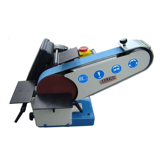
BELT / DISC SANDER
MODEL: DBG-62
Baileigh Industrial, Inc.
P.O. Box 531
Manitowoc, WI 54221-0531
Phone: 920.684.4990
Fax: 920.684.3944
sales@baileigh.com
REPRODUCTION OF THIS MANUAL IN ANY FORM WITHOUT WRITTEN APPROVAL OF BAILEIGH INDUSTRIAL, INC.
IS PROHIBITED. Baileigh Industrial, Inc. does not assume and hereby disclaims any liability for any damage or loss
caused by an omission or error in this Operator's Manual, resulting from accident, negligence, or other occurrence.
Rev. 02/2019
© 2019 Baileigh Industrial, Inc.
Advertisement
Table of Contents

Related Manuals for Baileigh DBG-62


Summary of Contents for Baileigh DBG-62
- Page 1 REPRODUCTION OF THIS MANUAL IN ANY FORM WITHOUT WRITTEN APPROVAL OF BAILEIGH INDUSTRIAL, INC. IS PROHIBITED. Baileigh Industrial, Inc. does not assume and hereby disclaims any liability for any damage or loss caused by an omission or error in this Operator’s Manual, resulting from accident, negligence, or other occurrence.
-
Page 2: Table Of Contents
Table of Contents THANK YOU & WARRANTY ..................1 INTRODUCTION ......................3 GENERAL NOTES ......................3 SAFETY INSTRUCTIONS ....................4 SAFETY PRECAUTIONS ....................6 Dear Valued Customer: ....................6 TECHNICAL SPECIFICATIONS ..................8 TECHNICAL SUPPORT ....................8 UNPACKING AND CHECKING CONTENTS ..............9 Cleaning ........................ -
Page 3: Thank You & Warranty
THANK YOU & WARRANTY Thank you for your purchase of a machine from Baileigh Industrial. We hope that you find it productive and useful to you for a long time to come. Inspection & Acceptance. Buyer shall inspect all Goods within ten (10) days after receipt thereof. Buyer’s payment shall constitute final acceptance of the Goods and shall act as a waiver of the Buyer’s rights to inspect or... - Page 4 Baileigh Industrial makes every effort to ensure that our posted specifications, images, pricing and product availability are as correct and timely as possible. We apologize for any discrepancies that may occur. Baileigh Industrial reserves the right to make any and all changes deemed necessary in the course of business including but not limited to pricing, product specifications, quantities, and product availability.
-
Page 5: Introduction
After receiving your equipment remove the protective container. Do a complete visual inspection, and if damage is noted, photograph it for insurance claims and contact your carrier at once, requesting inspection. Also contact Baileigh Industrial and inform them of the unexpected occurrence. Temporarily suspend installation. -
Page 6: Safety Instructions
IMPORTANT PLEASE READ THIS OPERATORS MANUAL CAREFULLY It contains important safety information, instructions, and necessary operating procedures. The continual observance of these procedures will help increase your production and extend the life of the equipment. SAFETY INSTRUCTIONS LEARN TO RECOGNIZE SAFETY INFORMATION This is the safety alert symbol. - Page 7 SAVE THESE INSTRUCTIONS. Refer to them often and use them to instruct others. PROTECT EYES Wear safety glasses or suitable eye protection when working on or around machinery. DUST HAZARD Wear appropriate dust mask. Dust created while using machinery can cause cancer, birth defects, and long term respiratory damage.
-
Page 8: Safety Precautions
Baileigh does not recommend or endorse making any modifications or alterations to a Baileigh machine. Modifications or alterations to a machine may pose a substantial risk of injury to the operator or others and may do substantial damage to the machine. - Page 9 8. Do not force tool. Your machine will do a better and safer job if used as intended. DO NOT use inappropriate attachments in an attempt to exceed the machine’s rated capacity. 9. Use the right tool for the job. DO NOT attempt to force a small tool or attachment to do the work of a large industrial tool.
-
Page 10: Technical Specifications
(other than die sets and blades). For specific application needs or future machine purchases contact the Sales Department at: sales@baileigh.com, Phone: 920.684.4990, or Fax: 920.684.3944. Note: The photos and illustrations used in this manual are representative only and may not depict the actual color, labeling or accessories and may be intended to illustrate technique only. -
Page 11: Unpacking And Checking Contents
UNPACKING AND CHECKING CONTENTS Your Baileigh machine is shipped complete. Separate all parts from the packing material and check each item carefully. Make certain all items are accounted for before discarding any packing material. WARNING: SUFFOCATION HAZARD! Immediately discard any plastic bags and packing materials to eliminate choking and suffocation hazards to children and animals. -
Page 12: Installation
Anchoring the Machine If you intend to mount the Baileigh machine on a workbench be aware of the following: • Overall weight of the machine and the weight of material being processed. -
Page 13: Overall Dimensions
OVERALL DIMENSIONS 19.68” (max.) 16.14” [500] [410] GETTING TO KNOW YOUR MACHINE... - Page 14 Item Part Name Driving Wheel Belt Graphite Layer Contact Wheel Grinding / Sanding Disc Motor Hinged Guard Bed Adjustment Bolts Belt Tightening Handle Belt Tracking Adjustment Working Table Assembly Belt Working Table Belt Material Stop...
-
Page 15: Electrical
ELECTRICAL CAUTION: HAVE ELECTRICAL UTILITIES CONNECTED TO MACHINE BY A CERTIFIED ELECTRICIAN! Check if the available power supply is the same as listed on the machine nameplate. WARNING: Make sure the grounding wire (green) is properly connected to avoid electric shock. DO NOT switch the position of the green grounding wire if any electrical plug wires are switched during hookup. - Page 16 • Improper connection of the equipment-grounding conductor can result in risk of electric shock. The conductor with insulation having an outer surface that is green with or without yellow stripes is the equipment-grounding conductor. If repair or replacement of the electric cord or plug is necessary, do not connect the equipment-grounding conductor to a live terminal.
-
Page 17: Operation
To access the START/STOP buttons, slide the button and the cover will open. 1. Plug the DBG-62 into a properly grounded 110V power source. 2. Open the Start/Stop switch cover. To start the sander press the GREEN Start button. -
Page 18: Machine Adjustments
MACHINE ADJUSTMENTS Belt Tracking Upon starting the machine, the belt may track either left or right. The tracking can be adjusted by turning knob (10) clockwise (cw) to move the belt to the left, or counterclockwise (ccw) to move the belt to the right. figure 3 Changing the Graphite Layer 1. -
Page 19: Changing The Disc
Changing the Disc 1. Shut off the machine, making sure the driving wheel has completely stopped. 2. Remove the working table assembly (11). 3. Peel off the used disc which utilizes a hook and loop method of attachment as shown in (fig. 5). 4. -
Page 20: Adjustable Tables
Adjustable Tables The Baileigh DBG-62 Belt / Disc Sander has three independent and adjustable tables as shown in (fig. 8) below. Each one can be set to accommodate various sanding / grinding situations. The two lower tables can be set at 90° to the sanding surface... -
Page 21: Lubrication And Maintenance
LUBRICATION AND MAINTENANCE WARNING: Make sure the electrical disconnect is OFF before working on the machine. Maintenance should be performed on a regular basis by qualified personnel. Always follow proper safety precautions when working on or around any machinery. • Check daily for any unsafe conditions and fix immediately. •... -
Page 22: Parts Identification Drawing
PARTS IDENTIFICATION DRAWING... -
Page 23: Parts Identification List
PARTS IDENTIFICATION LIST Item Description Base Plate Bolt M8 x 70mm Washer 8mm Bushing Safety Guard Working Table Large Washer 8mm Handle M8 x 12 x 40mm Bolt M6 x 25mm Washer 6mm Bolt M6 x 20mm Motor Disc Layer Driving Wheel Front Guard Graphite Layer... - Page 24 Item Description Bracket Bearing Washer 10mm Shaft Spring Rear Wheel Spring Switch Bolt M5 x 60mm Bolt M8 x 20 Support...
-
Page 25: Electrical Schematic
ELECTRICAL SCHEMATIC Stop Start Electromagnetic Switch MAIN MOTOR 1Hp (.74Kw) -
Page 26: Troubleshooting
TROUBLESHOOTING WARNING: Make sure the electrical disconnect is OFF before working on the machine. FAULT PROBABLE CAUSE REMEDY 1. No power 1. Check the power source. MOTOR DOES NOT 2. Motor defective. 2. Replace motor. 1. Improper belt splice. 1. Check belt for irregular seam or shape. POOR TRACKING 2. - Page 28 BAILEIGH INDUSTRIAL, INC. 1625 D , WI 54220 UFEK RIVE ANITOWOC : 920. 684. 4990 F : 920. 684. 3944 HONE www.baileigh.com BAILEIGH INDUSTRIAL LTD. U WIFT OINT WIFT ALLEY NDUSTRIAL STATE UGBY , CV21 1QH U IDLANDS NITED INGDOM...