Yamaha RX-A3040 Easy Setup Manual
Hide thumbs
Also See for RX-A3040:
- Owner's manual (182 pages) ,
- Quick manual (8 pages) ,
- Additional information (8 pages)
Advertisement
Quick Links
English
AV Receiver/Receptor AV
RX-A3040/RX-A2040
© 2014 Yamaha Corporation
Easy Setup Guide/Guía de configuración sencilla
Printed in Malaysia ZK67880
This document explains basic connections and unit settings.
For more information about this product, refer to the Owner's Manual included on the supplied
CD-ROM.
The latest Owner's Manual can be downloaded from the following website.
http://download.yamaha.com/
Este documento describe las conexiones básicas y la configuración de la unidad.
Para obtener más información sobre este producto, consulte el Manual de Instrucciones que
se incluye en el CD-ROM suministrado.
Puede descargar el Manual de Instrucciones más reciente en el siguiente sitio Web.
http://download.yamaha.com/
1
3
1
4
5
2
English
Español
Accessories used with this
Accesorios empleados con
document
este documento
1 Remote control
1 Mando a distancia
2 Batteries (AAA, R03, UM-4) (x2)
2 Pilas (AAA, R03, UM-4) (x2)
3 YPAO microphone
3 Micrófono YPAO
4 Wireless antenna
4 Antena inalámbrica
5 Power cable
5 Cable de alimentación
The supplied power cable varies
El cable de alimentación suministrado
depending on the region of purchase.
varía según la región en la que se realice
la compra.
The following cables (not supplied) are
Se requieren los siguientes cables (no
required to build the system described
suministrados) para crear el sistema
in this document.
descrito en este documento.
• Speaker cables (depending on the
• Cables de altavoz (dependiendo del
number of speakers)
número de altavoces)
• Audio pin cable (x1)
• Cable de audio con patillas (x1)
• HDMI cables (x3)
• Cables HDMI (x3)
• Network cable
• Cable de red
2
*
E
R
0.5 to 1 m
0.5 to 1 m
De 0,5 a 1 m
De 0,5 a 1 m
1
2
1.8 m
1.8 m
1,8 m
1,8 m
3
9
4
5
10° to 30°
10° to 30°
De 10° a 30°
De 10° a 30°
0.3 m or more
0,3 m o más
6
7
English
Español
Placing speakers
Colocación de los altavoces
Set up the speakers in the room using the
Configure los altavoces en la sala
diagram as a reference.
utilizando el diagrama como referencia.
1 Front speaker (L)
1 Altavoz delantero (Izq.)
2 Front speaker (R)
2 Altavoz delantero (Der.)
3 Center speaker
3 Altavoz central
4 Surround speaker (L)
4 Altavoz surround (Izq.)
5 Surround speaker (R)
5 Altavoz surround (Der.)
6 Surround back speaker (L)
6 Altavoz surround trasero (Izq.)
7 Surround back speaker (R)
7 Altavoz surround trasero (Der.)
E Front presence speaker (L)*
E Altavoz de presencia delantero (Izq.)*
R Front presence speaker (R)*
R Altavoz de presencia delantero (Der.)*
9 Subwoofer
9 Subgraves
* For 9.1-channel system
* Para sistema de 9.1 canales
4
Español
RGL
TV
TV
HDMI
HDMI input
Entrada HDMI
HDMI
The unit
La unidad
HDMI
HDMI
HDMI
DC OUT
5V 0.5A
HDMI OUT
2
1
(1 BD/DVD)
(ZONE OUT)
ARC
PHONO
AV 1
AV 2
AV 3
AV 4
AV OUT
MONITOR OUT/
Y
P
P
Y
(1 BD/DVD)
B
R
ZONE OUT
GND
A
Y
P
P
Y
AV 1
B
R
AUDIO 1
AUDIO 2
AUDIO 3
AUDIO 4
L
(2 TV)
R
FRONT
1
COAXIAL
2
COAXIAL
3
OPTICAL
4
OPTICAL
5
OPTICAL
6
COAXIAL
SURROUND
R
ANTENNA
HD Radio
(4 RADIO)
AM
FM
75
3
Audio pin
cable
Cable de audio
con patillas
9
5
4
Subwoofer
Surround
Surround
speaker (R)
speaker (L)
Altavoz de subgraves
Altavoz
Altavoz
Use a subwoofer equipped
surround (Der.)
surround (Izq.)
with built-in amplifier.
Utilice un altavoz de
subgraves con un
amplificador incorporado.
1
2
10 mm
10 mm
English
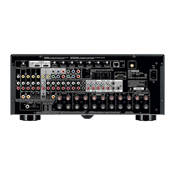
Connecting speakers/subwoofer
• When connecting 6-ohm speakers, set the unit's speaker impedance to "6 Ω MIN".
For details, see "Setting the speaker impedance" in the Owner's Manual.
• Before connecting the speakers, remove the unit's power cable from the AC wall outlet and
turn off the subwoofer.
• Ensure that the core wires of the speaker cable do not touch one another or come into
contact with the unit's metal parts. Doing so may damage the unit or the speakers. If the
speaker cables short circuit, "Check SP Wires" will appear on the front display when the unit
is turned on.
HDMI output
BD/DVD player
Salida HDMI
Reproductor BD/DVD
English
HDMI
Connecting external devices
HDMI output
Salida HDMI
Español
HDMI
HDMI
Conexión de los dispositivos
externos
Satellite/cable set top box
Reproductor digital
multimedia por cable/satélite
HDMI
COMPONENT VIDEO
TRIGGER
AV 2
P
P
OUT
B
R
B
1
REMOTE
1
2
IN
OUT
IN
OUT
2
C
P
P
12V 0.1AMAX. TOTAL
AV 3
B
R
MULTI CH INPUT
ZONE OUT/PRE OUT
PRE OUT
CENTER
(SINGLE)
(FRONT)
1
2
ZONE 2/
ZONE 3/
(REAR)
SURROUND
SUR. BACK
SUBWOOFER
FRONT
SURROUND
SUR. BACK
CENTER
F.PRESENCE
R.PRESENCE
SUBWOOFER
SPEAKERS
ZONE 2/ZONE 3/F.PRESENCE/
SURROUND BACK
ZONE 2/ZONE 3/R.PRESENCE/
CENTER
FRONT
L
R
L
R
L
BI-AMP
R
L
EXTRA SP2
R
EXTRA SP1
SINGLE
7
6
3
Surround back
Surround back
Center speaker
speaker (R)
speaker (L)
Altavoz central
Altavoz delantero (Der.)
Altavoz surround
Altavoz surround
trasero (Der.)
trasero (Izq.)
3
4
For 9.1-channel system
Para sistema de 9.1 canales
Español
Conexión de los altavoces y el subgraves
• Si conecta altavoces de 6 Ω, ajuste la impedancia de los altavoces de la unidad en "6 Ω MIN".
Para ver más detalles, consulte "Ajuste de la impedancia de los altavoces" en el Manual de
Instrucciones.
• Antes de conectar los altavoces, retire el cable de alimentación de la unidad de la toma de
CA y apague el altavoz de subgraves.
• Asegúrese de que los hilos del núcleo del cable de altavoz no se tocan entre sí o de que no
entran en contacto con las partes metálicas de la unidad. Esto puede dañar la unidad o los
altavoces. Si se produce un cortocircuito en los cables de los altavoces, aparecerá "Check
SP Wires" en el visor delantero cuando se enciende la unidad.
5
Network cable
Cable de red
English
Connecting a router for wired network connection
This procedure is unnecessary if the unit will be used with a wireless network
connection. Instead, perform procedures
Español
Conexión de un enrutador para conexión de red con
cable
Este procedimiento es innecesario si la unidad se va a utilizar con una conexión
* The shape and location of the
de red inalámbrica. En su lugar, realice los procedimientos
jacks may differ depending on
the model of the unit.
* La forma y la ubicación de las
tomas puede variar en función
6
del modelo de la unidad.
VOLTAGE SELECTOR
VOLTAGE SELECTOR
L
(General model only)
(Solo el modelo general)
English
Connecting the wireless
antenna
1.
Rotate the antenna clockwise.
2.
Stand the antenna up straight.
• Do not connect the antenna other than the
supplied one.
• Do not apply excessive force on the
antenna. Doing so may damage it.
• When packing the unit, remove the antenna
to prevent damage.
7
2
1
Front speaker (R)
Front speaker (L)
Altavoz delantero (Izq.)
(FRONT)
1
R
E
2
Front presence
Front presence
(REAR)
CENTER
SUBWOOFER
speaker (R)
speaker (L)
Altavoz de presencia
Altavoz de presencia
delantero (Der.)
delantero (Izq.)
English
Connecting the power cable to
an AC wall outlet
Before connecting the power cable
(General model only).
Set the switch position of VOLTAGE
SELECTOR according to your local
voltage.
Voltages are
AC 110–120/220–240 V, 50/60 Hz.
Internet
Router
Internet
Enrutador
LAN
Modem
Módem
6
and
10
.
6
y
10
.
Español
Conexión de la antena
inalámbrica
1.
Gire la antena en el sentido de
las agujas del reloj.
2.
Coloque la antena en posición
vertical.
• Conecte únicamente la antena
suministrada.
• No ejerza fuerza excesiva en la antena.
Podría dañarla.
• Al embalar la unidad, retire la antena para
evitar daños.
To an AC wall outlet
A una toma de CA
Español
Conexión del cable de
alimentación a una toma de CA
Antes de conectar el cable de
alimentación (solo el modelo general).
Ajuste la posición del conmutador
VOLTAGE SELECTOR según su tensión
local.
Las tensiones son
110–120/220–240 V CA, 50/60 Hz.
Advertisement

Related Manuals for Yamaha RX-A3040


Summary of Contents for Yamaha RX-A3040
- Page 1 Router Internet RX-A3040/RX-A2040 HDMI Enrutador Connecting external devices Network cable © 2014 Yamaha Corporation Cable de red Easy Setup Guide/Guía de configuración sencilla Printed in Malaysia ZK67880 HDMI output Salida HDMI This document explains basic connections and unit settings. Español HDMI For more information about this product, refer to the Owner’s Manual included on the supplied...
- Page 2 (YPAO) The Yamaha Parametric room Acoustic Optimizer (YPAO) function detects speaker connections, measures the distances from them to your listening position(s), and then La función Yamaha Parametric room Acoustic Optimizer (YPAO) detecta las conexiones English Español automatically optimizes the speaker settings, such as volume balance and acoustic de los altavoces, mide las distancias desde estos a su posición de escucha y optimiza...