Yamaha RX-V673 Service Manual
Hide thumbs
Also See for RX-V673:
- Owner's manual (138 pages) ,
- Code list (13 pages) ,
- Quick manual (4 pages)
Table of Contents
Advertisement
Note:
When the DIGITAL P.C.B. or IC82 on DIGITAL P.C.B. is replaced, this unit will display "Internal Error"
and will not operate at all without additional setting.
In such a case, report the serial number of this unit to the following e-mail address.
Yamaha Corporation will reply providing the setting procedure to make this unit operate properly.
This manual has been provided for the use of authorized YAMAHA Retailers and their service personnel.
It has been assumed that basic service procedures inherent to the industry, and more specifi cally YAMAHA Products, are already known
and understood by the users, and have therefore not been restated.
WARNING:
IMPORTANT:
The data provided is believed to be accurate and applicable to the unit(s) indicated on the cover. The research, engineering, and service
departments of YAMAHA are continually striving to improve YAMAHA products. Modifications are, therefore, inevitable and
specifi cations are subject to change without notice or obligation to retrofi t. Should any discrepancy appear to exist, please contact the
distributor's Service Division.
WARNING:
IMPORTANT:
■ CONTENTS
To Service Personnel ............................................2
Front Panels .........................................................3–4
Rear Panels ...........................................................5–8
Remote Control Panel ..........................................9
Specifications ................................................... 10–15
Internal View .................................................... 16–17
Service Precautions ............................................ 17
Disassembly Procedures ............................. 18–23
Updating Firmware ..........................................24–25
Self-Diagnostic Function ............................26–64
POWER AMPLIFIER ADJUSTMENT ............................65
1 0 1 2 3 7
RX-V673/HTR-6065/
E-mail: ycav-ysiss@gmx.yamaha.com
Failure to follow appropriate service and safety procedures when servicing this product may result in personal injury,
destruction of expensive components, and failure of the product to perform as specifi ed. For these reasons, we advise
All YAMAHA product owners that any service required should be performed by an authorized YAMAHA Retailer or
the appointed service representative.
The presentation or sale of this manual to any individual or fi rm does not constitute authorization, certifi cation or
recognition of any applicable technical capabilities, or establish a principle-agent relationship of any form.
Static discharges can destroy expensive components. Discharge any static electricity your body may have
accumulated by grounding yourself to the ground buss in the unit (heavy gauge black wires connect to this buss).
Turn the unit OFF during disassembly and part replacement. Recheck all work before you apply power to the unit.
Copyright © 2012
This manual is copyrighted by YAMAHA and may not be copied or
redistributed either in print or electronically without permission.
AV RECEIVER
RX-A720
SERVICE MANUAL
IMPORTANT NOTICE
DISPLAY DATA .......................................................66–69
IC DATA ...................................................................70–89
PIN CONNECTION DIAGRAMS .............................90–91
BLOCK DIAGRAMS ................................................92–95
PRINTED CIRCUIT BOARDS ............................... 96–128
SCHEMATIC DIAGRAMS ................................... 129–148
REPLACEMENT PARTS LIST ............................ 149–171
REMOTE CONTROL ........................................... 172–174
ADVANCED SETUP ............................................ 175–176
FIRMWARE UPDATING PROCEDURE .............. 177–188
All rights reserved.
P.O.Box 1, Hamamatsu, Japan
'12.05
Advertisement
Table of Contents

Related Manuals for Yamaha RX-V673


Summary of Contents for Yamaha RX-V673
- Page 1 This manual has been provided for the use of authorized YAMAHA Retailers and their service personnel. It has been assumed that basic service procedures inherent to the industry, and more specifi cally YAMAHA Products, are already known and understood by the users, and have therefore not been restated.
- Page 2 RX-V673/HTR-6065/RX-A720 ■ TO SERVICE PERSONNEL AC LEAKAGE 1. Critical Components Information WALL EQUIPMENT TESTER OR OUTLET UNDER TEST EQUIVALENT Components having special characteristics are marked must be replaced with parts having specifications equal to those originally installed. 2. Leakage Current Measurement (For 120V Models Only)
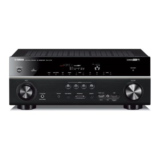
- Page 3 RX-V673/HTR-6065/RX-A720 ■ FRONT PANELS RX-V673 (U, C, R, T, K, A, B, G, F, L, S, H models) HTR-6065 (A, F models)
- Page 4 RX-V673/HTR-6065/RX-A720 RX-A720 (U, C, A models)
- Page 5 RX-V673/HTR-6065/RX-A720 ■ REAR PANELS RX-V673 (U, C models) RX-V673 (R, S models) RX-V673 (T model)
- Page 6 RX-V673/HTR-6065/RX-A720 RX-V673 (K model) RX-V673 (A model) RX-V673 (B, G, F models)
- Page 7 RX-V673/HTR-6065/RX-A720 RX-V673 (L, H models) H model HTR-6065 (A model) HTR-6065 (F model)
- Page 8 RX-V673/HTR-6065/RX-A720 RX-A720 (U, C models) RX-A720 (A model)
- Page 9 RX-V673/HTR-6065/RX-A720 ■ REMOTE CONTROL PANEL RAV472 Remote control sheet (T model)
- Page 10 RX-V673/HTR-6065/RX-A720 ■ SPECIFICATIONS ■ Audio Section Rated Output Power (Power Amp. Section) Tone Control Characteristics (1 kHz, 0.9 % THD) Bass Boost/Cut ........±6 dB / 0.5 dB step, at 50 Hz – 1 channel driven – Turnover frequency ............. 350 Hz...
- Page 11 RX-V673/HTR-6065/RX-A720 ■ AM Section Tuning Range Accessories U, C models ............530 to 1,710 kHz Remote control ................x 1 R, L, S, H models ......530 to 1,710 / 531 to 1,611 kHz Batteries (R03, AAA, UM-4) ............x 2 T, K, A, B, G, F models .......... 531 to 1,611 kHz FM antenna (1.4 m) ..............x 1...
- Page 12 RX-V673/HTR-6065/RX-A720 “SILENT CINEMA” is a trademark of Yamaha Corporation. Windows is a registered trademark of Microsoft Corporation in the United States and other countries. Windows XP, Windows Vista, Windows 7 , Windows Media Audio, Windows Media Connect and Windows Media Player are either registered trademarks or trademarks of Microsoft Corporation in the United States and/or other DLNA™...
- Page 13 RX-V673/HTR-6065/RX-A720 • SELECT MENU Sound field parameters Category Program MOVIE THEATER Standard ● ● ● ○ ● ○ ● ○ ● Spectacle ● ● ● ● ○ ● ● ○ ● Sci-Fi ● ● ● ● ○ ● ● ○...
- Page 14 RX-V673/HTR-6065/RX-A720 • SET MENU TABLE MAIN MENU SUB-MENU PARAMETER VALUE [INITIAL VALUE] Speaker Auto Measure Optimizes the speaker configuration automatically using YPAO. Setup Result Not Available Manual Power Amp Assign [Basic] / 7ch +1ZONE / 5ch BI-AMP Configuration Front Large / [Small] When “Subwoofer”...
- Page 15 RX-V673/HTR-6065/RX-A720 MAIN MENU SUB-MENU PARAMETER VALUE [INITIAL VALUE] Sound Setup Dynamic Range [Maximum] / Standard / Minimum/Auto Max. Volume -30.0 to +16.5 dB (Maximum volume), [+16.5 dB], 5.0 dB step Initial Volume [Off] / On Select “On” Mute, -80 to +16.5 dB, 0.5 dB step...
- Page 16 RX-V673/HTR-6065/RX-A720 ■ INTERNAL VIEW RX-V673/HTR-6065 Top view VIDEO (2) P.C.B. VIDEO (3) P.C.B. VIDEO (8) P.C.B. (R, S models) OPERATION (8) P.C.B. MAIN (2) P.C.B. DIGITAL (1) P.C.B. VIDEO (1) P.C.B. VIDEO (4) P.C.B. AM/FM TUNER OPERATION (2) P.C.B. OPERATION (12) P.C.B.
- Page 17 RX-V673/HTR-6065/RX-A720 RX-A720 Top view VIDEO (2) P.C.B. VIDEO (3) P.C.B. OPERATION (8) P.C.B. MAIN (2) P.C.B. DIGITAL (1) P.C.B. VIDEO (1) P.C.B. VIDEO (4) P.C.B. AM/FM TUNER OPERATION (2) P.C.B. OPERATION (7) P.C.B. OPERATION (11) P.C.B. OPERATION (9) P.C.B. (U, C models) OPERATION (10) P.C.B.
- Page 18 RX-V673/HTR-6065/RX-A720 ■ DISASSEMBLY PROCEDURES RX-V673/HTR-6065 (Remove parts in the order as numbered.) Disconnect the power cable from the AC outlet. 1. Removal of Top Cover a. Remove 4 screws ( ① ) and 5 screws ( ② ). (Fig. 1) b.
- Page 19 RX-V673/HTR-6065/RX-A720 3. Removal of DIGITAL (1) P.C.B. 4. Removal of AMP Unit and Power Transformer a. Remove screw ( ④ ) and 7 screws ( ⑤ ). (Fig. 3) a. Remove screw ( ⑦ ), 3 screws ( ⑧ ), 3 screws ( ⑨ ) and b.
- Page 20 RX-V673/HTR-6065/RX-A720 When checking the P.C.B.s: • Place the P.C.B.s (with rear panel) upright. (Fig. 4) • Connect the heatsink and rear panel to the chassis with a ground lead. (Fig. 4) • Reconnect all cables (connectors) that have been disconnected.
- Page 21 RX-V673/HTR-6065/RX-A720 RX-A720 (Remove parts in the order as numbered.) Disconnect the power cable from the AC outlet. 1. Removal of Top Cover a. Remove 4 screws ( ① ), 5 screws ( ② ) and screw ( ③ ). (Fig. 1) b.
- Page 22 RX-V673/HTR-6065/RX-A720 3. Removal of DIGITAL (1) P.C.B. 4. Removal of AMP Unit and Power Transformer a. Remove screw ( ⑥ ) and 7 screws ( ⑦ ). (Fig. 3) a. Remove screw ( ⑨ ), 3 screws ( ⑩ ), 3 screws ( ⑪ ) and b.
- Page 23 RX-V673/HTR-6065/RX-A720 When checking the P.C.B.s: • Place the P.C.B.s (with rear panel) upright. (Fig. 4) • Connect the heatsink and rear panel to the chassis with a ground lead. (Fig. 4) • Reconnect all cables (connectors) that have been disconnected.
- Page 24 USB storage device • Firmware RX-V673/HTR-6065/RX-A720: R0309-xxxx.bin ● Preparation 1. Download the latest firmware from the specified download source to the folder of the PC. 2. Copy the latest firmware from the PC to the root folder of the USB storage device.
- Page 25 RX-V673/HTR-6065/RX-A720 ● Operation Procedures 1. Insert the USB storage device to the USB jack. (Fig. 1) 2. While pressing the “PURE DIRECT” key, connect the power cable to the AC outlet. (Fig. 1) "MAIN ZONE " key "PURE DIRECT" key...
- Page 26 RX-V673/HTR-6065/RX-A720 ■ SELF-DIAGNOSTIC FUNCTION This unit has self-diagnostic functions that are intended for inspection, measurement and location of faulty point. There are 22 main menu items, each of which has sub-menu items. Listed in the table below are main menu items and sub-menu items.
- Page 27 RX-V673/HTR-6065/RX-A720 Main menu Sub-menu D: Display system FL CHECK FL CHECK ALL SEGMENT OFF ALL SEGMENT ON CHECK PATTERN 1 CHECK PATTERN 2 Z: Zone system ZONE TEST (Not for service) (Not for service) (Not for service) (Not for service)
- Page 28 RX-V673/HTR-6065/RX-A720 Main menu Sub-menu V: Video system ANALOG VIDEO CHECK ANALOG BYPASS INVALID ITEM (Not for service) INVALID ITEM (Not for service) MUTE CHECK TEST PATTERN (Not for service) VIDEO IN DIGITAL VIDEO CHECK LOOPBACK TEST 1 LOOPBACK TEST 2...
- Page 29 RX-V673/HTR-6065/RX-A720 Main menu Sub-menu P: Power and protection system SYSTEM MONITOR PS1/PS2/PS3 INVALID ITEM (Not for service) OUTPUT LEVEL LIMITER CONTROL L3 (J model) (Not for service) KEY1/KEY2 USB-VBUS (Not for service) PROTECTION HISTORY HISTORY 1 HISTORY 2 HISTORY 3...
- Page 30 RX-V673/HTR-6065/RX-A720 ● Starting Self-Diagnostic Function While pressing the “TONE CONTROL” and “INFO” keys, press the “MAIN ZONE ” key to turn on the power, and release those 2 keys. The self-diagnostic function mode is activated. Keys of this unit RX-V673/HTR-6065 While pressing these keys, turn on the power.
- Page 31 RX-V673/HTR-6065/RX-A720 ● Canceling Self-Diagnostic Function Before canceling self-diagnostic function, execute setting for “S3. FACTORY PRESET” menu. (Memory initialization inhibited or Memory initialized). In order to keep the user memory preserved, be sure to select PRESET INHIBIT (Memory initialization inhibited). Press the “MAIN ZONE ” key to turn off the power.
- Page 32 RX-V673/HTR-6065/RX-A720 2-2. When the protection function worked due to abnormal DC output. H: Displayed when the voltage is HIGHER than upper limit L: Displayed when the voltage is LOWER than lower limit D C P R T : x x x H xxx: A/D conversion value of voltage at the moment when the protection function worked (Reference voltage: 3.3 V=255)
- Page 33 RX-V673/HTR-6065/RX-A720 2-4. When the protection function worked due to excessive heatsink temperature. H: Displayed when the voltage is HIGHER than upper limit L: Displayed when the voltage is LOWER than lower limit T M P P R T : x x x L xxx: A/D conversion value of voltage at the moment when the protection function worked (Reference voltage: 3.3 V=255)
- Page 34 RX-V673/HTR-6065/RX-A720 ● Operation procedure of Main menu and Sub-menu There are 22 main menu items, each of which has sub-menu items. Main menu selection Select the main menu using “SCENE TV” (forward) and “SCENE BD/DVD” (reverse) keys. Sub-menu selection Select the sub-menu using “SCENE RADIO” (forward) and “SCENE NET” (reverse) keys.
- Page 35 RX-V673/HTR-6065/RX-A720 ● Details of Self-Diagnostic Function menu A1. DSP AUDIO This menu is used to check audio signal route via DSP. A1-1. DSP MARGIN The audio signal is output including the head margin via DSP. * When input source is stereo, signal is assigned as below.
- Page 36 RX-V673/HTR-6065/RX-A720 A1-6. DSP FULL SURROUND BACK The audio signal is output to only SURROUND BACK L/R channel in digital full bit without including the head margin. A 1 - 6 D S P F U L L S B A1-7. DSP FULL SUBWOOFER The audio signal is output to only SUBWOOFER channel in digital full bit without including the head margin.
- Page 37 RX-V673/HTR-6065/RX-A720 A3. HDMI AUDIO This menu is used to check the route of audio signal input to HDMI IN/OUT jack. * Before check using “A3-3. ARC 1” menu, be sure to connect a TV monitor equipped with Audio Return Channel function to this unit in advance.
- Page 38 RX-V673/HTR-6065/RX-A720 A4. SPEAKERS SET This menu is used to check the speaker output. A4-1. BI-AMP A 4 - 1 B I - A M P The FRONT L/R signal is distributed to SURROUND BACK L/R terminals. A4-2. ZONE/TONE=MAX A 4 - 2...
- Page 39 RX-V673/HTR-6065/RX-A720 A5. MULTI CHANNEL INPUT Not for service. A 5 - 1 A 5 - 2 8 o h m M U L T I C H 6 o h m M U L T I C H A6. MIC CHECK A6-1.
- Page 40 RX-V673/HTR-6065/RX-A720 A7. MANUAL TEST The test noise generated by built-in noise generator in DSP is output to the channels specified by the sub-menu. Test noise Test tone 30 Hz to 80 Hz 50 Hz for SUBWOOFER pink noise sine wave...
- Page 41 RX-V673/HTR-6065/RX-A720 A7-10. TEST FRONT PRESENCE R A 7 - 1 0 T E S T F P R The test tone is output to FRONT PRESENCE R channel. A 7 - 1 1 A7-11. INVALID ITEM I N V A L I D I T E M Not for service.
- Page 42 RX-V673/HTR-6065/RX-A720 D1. FL CHECK This menu is used to check operation of the FL display. FL display D1-1. INITIAL DISPLAY D1-2. ALL SEGMENT OFF D1-3. ALL SEGMENT ON * After check, change to next menu at once. D1-4. CHECK PATTERN 1 Example Lighting on segments in lattice.
- Page 43 RX-V673/HTR-6065/RX-A720 Z1. ZONE TEST This menu is used to check audio signal route to ZONE2 OUT jack. Z1-1. AV1 Z 1 - 1 A V 1 Not for service. Z1-2. AV2 Z 1 - 2 A V 2 Not for service.
- Page 44 RX-V673/HTR-6065/RX-A720 U1. USB This menu is used to check the audio signal route from USB storage device. U1-1. USB FRONT 1 TRACK The 1st music file stored in the USB storage device connected to the USB jack is reproduced. * Copy 2 or more music files from PC to the root folder of the USB storage device in advance.
- Page 45 RX-V673/HTR-6065/RX-A720 N1-3. LINE NOISE 100 MDI Not for service. N 1 - 3 L N M D I 1 0 0 N1-4. LINE NOISE 100 MDIX Not for service. N 1 - 4 L N M D I X 1 0 0 N1-5.
- Page 46 RX-V673/HTR-6065/RX-A720 C1. DIGITAL P.C.B. CHECK This menu is used to check the communication and bus line connection between devices on DIGITAL P.C.B. C1-1. ALL The synthetic judgment result of sub-menu C1-2 to C1-8 is displayed. C 1 - 1 A L L : O K...
- Page 47 RX-V673/HTR-6065/RX-A720 C1-5. FPGA RAM SDRAM (IC53)’s reading/writing are checked. C 1 - 5 F P G A _ R A M : O K OK: No error detected NG: An error is detected C1-6. BUS DIR1 Communication and bus line connection between microprocessor (IC83) and DIR1 (IC924) are checked.
- Page 48 RX-V673/HTR-6065/RX-A720 C2. NETWORK IC CHECK This menu is used to check the communication and bus line connection between devices related to network. C2-1. ALL The synthetic judgment result of sub-menu C2-2 to C2-5 is displayed. C 2 - 1 A L L : O K E x t . J I G When test result using the “C2-2.
- Page 49 RX-V673/HTR-6065/RX-A720 C2-5. APL (Apple) ID CHECK Apple authentication IC (IC956) device ID is checked. C 2 - 5 A P L I D : O K OK: No error detected NG: An error is detected Checking V1. ANALOG VIDEO CHECK This menu is used to check the analog video signal route.
- Page 50 RX-V673/HTR-6065/RX-A720 V1-4. MUTE CHECK The video signal is muted. V 1 - 4 M U T E C H E C K MUTE CHECK HDMI IN HDMI OUT DIGITAL DIGITAL DIGITAL IC61 IC64 HDMI HDMI FPGA Receiver Transmitter DIGITAL Component In...
- Page 51 RX-V673/HTR-6065/RX-A720 V2. DIGITAL VIDEO CHECK This menu is used to check the digital video signal route. V2-1. LOOPBACK TEST 1 Execute the test for all HDMI IN jacks by repeating the procedure below. 1. Select sub-menu other than V2-1. 2. Connect between any of the HDMI IN jacks and HDMI OUT jack with an HDMI cable.
- Page 52 3. Select the input source corresponding to the connected HDMI IN jack by using “INPUT ” and “INPUT ” keys (RX-V673/HTR-6065) / “INPUT” knob (RX-A720). 4. Select V2-2. The test result is displayed in a few seconds. Select the input source...
- Page 53 3. Select the input source corresponding to the connected HDMI IN jack by using “INPUT ” and “INPUT ” keys (RX-V673/HTR-6065) / “INPUT” knob (RX-A720). 4. Select V2-3. The test result is displayed in a few seconds. Select the input source...
- Page 54 RX-V673/HTR-6065/RX-A720 V2-7. HDMI REPEAT The video/audio signals input to HDMI IN jack are output to HDMI OUT jack. V 2 - 7 H D M I R E P E A T * * The Deep Color video signals is input, “30” bit or “36”...
- Page 55 RX-V673/HTR-6065/RX-A720 V2-9. INVALID ITEM Not for service. V 2 - 9 I N V A L I D I T E M V2-10. DIGITAL COMPONENT The component video (Y, Cb, Cr) signal is converted and output as shown below. V 2 - 1 0...
- Page 56 RX-V673/HTR-6065/RX-A720 V2-11. DIGITAL COMPONENT SC The component video (Y, Cb, Cr) signal is converted and output as shown below. HDMI video output up-scaling: 480i/p, 576i/p only => 1080p V 2 - 1 1 D I G I T A L C m p S C...
- Page 57 RX-V673/HTR-6065/RX-A720 V3. TEST PATTERN The video signal is output to HDMI OUT jack with its resolution converted as shown below. HDMI CB30 CB61 HDMI IN HDMI HDMI HDMI HDMI HDMI HDMI Front OUT1 IC30 IC61 HDMI EQUALIZER HDMI IC53 TMDS261...
- Page 58 RX-V673/HTR-6065/RX-A720 P1. SYSTEM MONITOR This menu is used to display the A/D conversion value of the microprocessor which detects panel keys and protection functions by using the sub-menu. When “P1-7. KEY1/KEY2” sub-menu is selected, keys become inoperable due to detection of the values of all keys.
- Page 59 RX-V673/HTR-6065/RX-A720 P1-4. INVALID ITEM Not for service. P 1 - 4 I N V A L I D I T E M P1-5. OUTPUT LEVEL Output level of speaker output is detected. The voltage at 4 pin (AMP_OLV) of IC78 is displayed.
- Page 60 PRESET 97 – 119 ZONE2 100 – 121 > INPUT > PRESET 120 – 142 122 – 144 (RX-V673/HTR-6065 models) < INPUT < 143 – 172 145 – 166 MEMORY (RX-V673/HTR-6065 models) MAIN ZONE 173 – 202 167 – 186...