Advertisement
Quick Links
1 | Overview
The B440 provides IP communication over the Verizon 3G cellular network by directly connecting
the module to the control panel. The control panel can be confi gured for Personal Notifi cation
using the B440 module and a cellular network.
The B440 module requires active cellular service to communicate. Bosch Cellular devices are
shipped pre-activated with Bosch Cellular service.
1
1
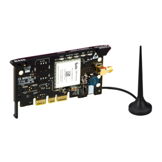
Figure 1.1: Module overview
Callout ― Description
1 ― Module handle and support leg
2 ― LEDs
3 ― Threaded female SMA antenna connector
4 ― Plug-in module retention clip opening
5 ― PCB metal contacts
2 | Install or remove the module
CAUTION!
Remove all power (AC and battery) before making any connections. Failure to do so
might result in personal injury and/or equipment damage.
2
3
4
5
2.1 | Install the antenna
Installing the antenna:
1.
Place the magnetic antenna on top of
the enclosure, or vertically on another
metal surface.
2.
Route the antenna cable through a
knock-out.
3.
Connect the antenna cable to the
module.
4.
Secure the antenna cable to the inside
of the enclosure.
Figure 2.2: Wiring the antenna
Callout ― Description
1 ― Antenna routed though any knock-out
2 ― Antenna cable connected to the
module
2.2 | Install the module
The control panel communicates with and
provides power to the module through the
plug-in connection. Proper installation results
in the necessary electrical and mechanical
connection.
Installing the module:
1.
With the module facing the control
panel as shown in Figure 2.2, insert
the support leg into the support hole
labeled X.
2.
Align the PCB metal contacts with the
on-board connector.
3.
Push the module into place. The
retention clip snaps closed and secures
the module in place.
Figure 2.2: Module installation
Callout ― Description
1 ― Support leg inserted into the control
panel support hole labeled X
2 ― PCB metal contacts resting on the
on-board connector
3 ― Plug-in module retention clip
2.3 | Remove the module
To remove an installed module, hold the plug-
in module retention clip open with one hand
while grasping the top corners of the module
support handle with your other hand. Pull
the module out.
3 | Diagnostic LED
descriptions
At power up, all B440 LEDs activate
for several seconds, indicating proper
insertion. The Signal LEDs then turn off
until the module registers on the cellular
network. Registering a new module
might take up to 2 min.
Check the LED display to ensure a
good signal strength level, and adjust
the antenna location as required. The
signal strength LEDs momentarily turn
off to indicate the module has measured
and updated the signal strength status.
Refer to Table 3.1.
Advertisement

Related Manuals for Bosch B440


Summary of Contents for Bosch B440
- Page 1 1 | Overview 2.1 | Install the antenna The B440 provides IP communication over the Verizon 3G cellular network by directly connecting Installing the antenna: the module to the control panel. The control panel can be confi gured for Personal Notifi cation Place the magnetic antenna on top of using the B440 module and a cellular network.
- Page 2 All hardware and software product names used in this document are likely to be registered trademarks and must be treated accordingly. Bosch Security Systems, Inc. product manufacturing dates Use the serial number located on the product label and refer to the Bosch Security Systems, Inc. website at © 2015 Bosch Security Systems, Inc.