Bosch B465 Quick Start Manual
Conettix universal dual path
communictor
Hide thumbs
Also See for B465:
- Quick start manual (2 pages) ,
- Installation and operation manual (115 pages)
Advertisement
Quick Links
1 | Overview
The B465 Conettix Universal Dual Path Communicator links the
digital dialer from a intrusion/fi re control panel to an Ethernet
connection on a local area network (LAN) or wide area network
(WAN).
1
2
MODULE 1
Y
X
MODULE
RELEASE
COMMUNICATION MODULE 1
ETHERNET
100BASE-T
LINK
USB
SYSTEM TROUBLE
TX
TX
RX
SDI2
POWER
Device Bus
PWR
R Y G B
BATTERY
INPUTS
2.2 k
End of
24 VDC
Line Resistors
or
PANEL
PANEL
16.5 VAC
1 COM 2
3 COM 4
BATTERY
LINE 1
LINE 2
+
-
T
R
16.5VAC
NC C NO
C
NO
C
NO
12V
1
COM
2
3
COM
4
T
R
BATTERY
RELAY 1
RELAY 2
RELAY 3
AUX COM
PNL LINE 1
PNL LINE 2
16
15
14
13
12
11
10
9
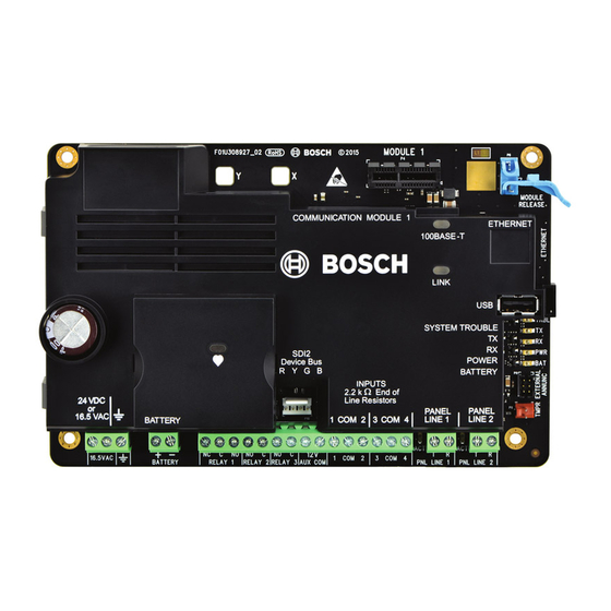
Callout ― Description
Callout ― Description
1 ― Holes to stabilize plug-in
9 ― Control panel phone line
modules
connectors
2 ― Plug-in module connector
10 ― Input loop terminals
(COM 1 to COM 4)
3 ― Plug-in module retention clip
11 ― 12V AUX/COM terminal
4 ― Ethernet connector
12 ― Programmable output
relays to a control panel
5 ― USB connector
13 ― Heartbeat LED
6 ― Status LEDs (SYSTEM
14 ― 12 VDC sealed lead-acid
TROUBLE, TX, RX, POWER, and
rechargeable battery terminals
BATTERY)
7 ― External Annunciator
15 ― Earth ground terminal
connector (connected to a B46)
8 ― Tamper switch
16 ― 16.5 VAC or 24 VDC
power supply input terminals
NOTICE!
The SDI2 Device Bus terminal connector located
above callouts 11 and 12 is for future use.
2 | Installation
This section describes basic installation procedures.
For information on confi guration, LED descriptions, and
troubleshooting refer to the B465 Installation and Operation
Guide (P/N: F01U311207).
NOTICE!
Notify the central station and the local authority
before installing the B465 in an existing system.
CAUTION!
Remove all power (AC and battery) before making
any connections. Failure to do so might result in
personal injury and/or equipment damage.
2.1 | Remove enclosure knockouts
Review knockout locations before installing. Each enclosure is
slightly diff erent regarding knockout locations. Use a hammer
and punch tool to remove the desired knockout locations. Use
pliers to remove metal debris.
1
2
3
4
5
1
6
7
8
1
4
Callout ― Description
1 ― Suggested knockout locations for B465 wiring
2 ― Knockouts for B46 LED cover and module (optional for non-fi re
applications)
3 ― Lockset mounting knockout
2.3 | Install the enclosure
Install the UL Listed enclosure such as the B10/B10R, B11/
B11R, or D8103 enclosure in the desired location.
2.4 | Install enclosure earth ground wiring
Install the supplied earth ground wire onto the inside clip of
the supporting enclosure door. Refer to the folowing graphic for
ground wire location.
1
2
3
3
Callout ― Description
1 ― B465 wiring label (label insertion location)
2 ― Earth ground wiring enclosure location
3 ― Enclosure mounting holes (4)
4 ― B46 mounting locations*
5 ― Tamper switch mounting locations (optional)
* Use the upper, right-hand 3-hole mounting location for installing the optional B46
module in a B10 enclosure.
2.5 | Apply the wiring label into the enclosure
Apply the supplied wiring label to the inside, enclosure door.
Refer to the graphic in section 2.3 for wiring label location.
2.6 | Install plastic standoff
Snap the four supplied plastic standoff s onto four enclosure
support posts. Refer tothe following graphics.
3
1
1
3
Callout ― Description
1 ― B10/B10R enclosure
2 ― B11/B11R enclosure
3 ― Mounting plastic standoff locations for B465
2.7 | Installing the screws
Install the B465 into the enclosure's 4-hole plastic standoff s
3
using the supplied screws and a slotted screwdriver. Refer
to the graphic below.
4
5
3
2.8 | Install the B46 module (optional)
Install the B46 into the enclosure's side, 3-hole mounting
pattern using the supplied mounting screws. Refer to
the following graphics. For more information on the B46
installation, refer to the B46 Installation and Operation Guide
(P/N: F01U312441).
Callout ― Description
1 ― Module with mounting bracket installed
2 ― Enclosure (side wall)
3 ― Mounting screws (3)
2
2
1
3
Callout ― Description
1 ― B46
2 ― Enclosure
2.9 | Install the cellular module (optional)
Install the module into the slot of the B465 until the module
"clicks" into place. Refer to Figure 2.9.
24 VDC
24
DC
or or
16.5 VAC
16.5 VAC
BATTE
TERY
16.5VAC
+ BAT -
Callout ― Description
1 ― B44x cellular module
2 ― Antenna
2.10 | Wire to the control panel
Refer to the enclosure wiring label supplied with the B465, or
the B465 Installation and Operation Guide for specifi c wire routing
information. Refer tothe following graphic for basic wiring
routes.
NOTICE!
The dialer message format sent by the B465 will
be the same dialer format which is transmitted to
the Central Station receiver from the Alarm control
panel. For example, if the SIA dialer format is sent
from the control panel to the B465, the B465 sends a
SIA dialer format to the Central Station receiver.
2
1
3
1
2
MODULE 1
Y
X
MODULE
RELEASE
C C OMMUNI
OMMUNIC C A A TION MODULE 1
TION MODULE 1
ETHERNET
ETHERNET
100BASE
100BASE- - T T
3
LINK
LINK
USB
USB
S S Y Y S S TEM T
TEM TR R OUBLE
OUBLE
TRBL
TX
TX
TX
SDI2
SDI2
RX
RX
RX
D D e e vice Bus
vice Bus
POWER
POWER
PWR
B B A A T T TE
TER R Y Y
BAT
R R Y Y G G B B
INPU
INPUT T S S
2.2 k
2.2 k
End of
End of
ine R R e e si sis s t t o o r r s s
L L ine
1 1 C C OM 2
OM 2
3 3 C C OM 4
OM 4
P P ANEL
ANEL
ANEL
P P ANEL
LINE 1
LINE 1
LINE 2
LINE 2
T
R
RELAY 1
NC
C
NO
RELAY 2
C
NO
C
RELAY 3
NO
AUX COM
12V
1
COM
2
3
COM
4
PNL LINE 1
T
R
PNL LINE 2
Callout ― Description
3 ― B465
Advertisement

Related Manuals for Bosch B465


Summary of Contents for Bosch B465
- Page 1 5 ― USB connector 13 ― Heartbeat LED 2 ― B11/B11R enclosure Install the module into the slot of the B465 until the module 6 ― Status LEDs (SYSTEM 14 ― 12 VDC sealed lead-acid 2.4 | Install enclosure earth ground wiring 3 ―...
- Page 2 Copyright Use compatible wiring when connecting a B465 to a intrusion/ Use the serial number located on the product label and refer to the Bosch Security UL 1610 – Central Station Burglar Alarm Units fi re control panel to establish communication. Refer to the Systems, Inc.