Bosch B443 Installation Manual
B44 series conettix cellular communicators
Hide thumbs
Also See for B443:
- Installation manual (2 pages) ,
- Installation manual (2 pages) ,
- Installation manual (18 pages)
Table of Contents
Advertisement
Advertisement
Table of Contents

Related Manuals for Bosch B443


Summary of Contents for Bosch B443
- Page 1 Conettix Cellular Communicators B44x Installation Manual...
-
Page 3: Table Of Contents
Conettix Cellular Communicators Table of contents | en Table of contents Cellular module introduction About documentation Bosch Security Systems, Inc. product manufacturing dates Component overview Installation Insert the SIM card Install the antenna Install the communicator Remove the communicator Diagnostic LED descriptions... -
Page 4: Cellular Module Introduction
All hardware and software product names used in this document are likely to be registered trademarks and must be treated accordingly. Bosch Security Systems, Inc. product manufacturing dates Use the serial number located on the product label and refer to the Bosch Security Systems, Inc. website at http://www.boschsecurity.com/datecodes/. 2018.04 | 02 | F.01U.345.070 Installation Manual Bosch Security Systems, Inc. -
Page 5: Component Overview
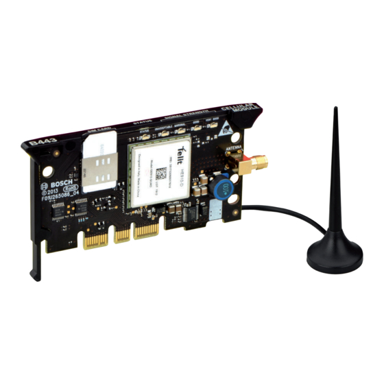
5 - PCB metal contacts Notice! The B440-C/B441-C communicators must be activated and have a valid cellular plan for proper usage. Refer to Activating the B440-C/B441-C, page 12 for details. Bosch Security Systems, Inc. Installation Manual 2018.04 | 02 | F.01U.345.070... - Page 6 1 - Module handle and support leg 2 - SIM card holder 3 - LEDs 4 - Threaded female SMA antenna connector 5 - Plug-in module retention clip opening 6 - PCM metal contacts 2018.04 | 02 | F.01U.345.070 Installation Manual Bosch Security Systems, Inc.
-
Page 7: Installation
Put the magnetic antenna on top of the enclosure, or vertically on another metal surface. Put the antenna cable through a knockout. Connect the antenna cable to the module. Make sure the antenna cable is inside the enclosure. Bosch Security Systems, Inc. Installation Manual 2018.04 | 02 | F.01U.345.070... -
Page 8: Install The Communicator
Put the support leg into the support hole labeled X. Refer to Figure 3.3. Align the PCB metal contacts with the on-board connector. Push the module into place. The retention clip snaps closed and secures the module in place. 2018.04 | 02 | F.01U.345.070 Installation Manual Bosch Security Systems, Inc. - Page 9 Plug-in communicator interface installation Insert the communicator into the slot of the plug-in communicator interface. Push in until you feel it "click" into place. Figure 3.4: Communicator installation (B450 shown) Bosch Security Systems, Inc. Installation Manual 2018.04 | 02 | F.01U.345.070...
-
Page 10: Remove The Communicator
3 - Plug-in communicator interface Remove the communicator Hold the plug-in module retention clip open. Hold the top corners of the module support handle with your other hand. Pull the module out. 2018.04 | 02 | F.01U.345.070 Installation Manual Bosch Security Systems, Inc. -
Page 11: Diagnostic Led Descriptions
LED Trouble State: Indicates communicator is not powered, or some other trouble condition prohibits the communicator from controlling the STATUS LED. (Check for proper installation.) Tab. 4.2: STATUS LED descriptions Bosch Security Systems, Inc. Installation Manual 2018.04 | 02 | F.01U.345.070... -
Page 12: Configuration
Communicator programming is done through the compatible control panel, plug-in communicator interface, or universal dual path communicator. Refer to the documentation of these devices or remote programming software help for more information. For Bosch Cellular account status and management, use RPS or the online service portal (go to http:// www.conettix.com/Cellular.aspx and click on the Cellular Portal Login link). -
Page 13: Specifications
Conettix Cellular Communicators Specifications | en Specifications Refer to the communicator graphical installation manuals for communicator specification information. Bosch Security Systems, Inc. Installation Manual 2018.04 | 02 | F.01U.345.070... - Page 15 Bosch Security Systems, Inc. Bosch Sicherheitssysteme GmbH 130 Perinton Parkway Robert-Bosch-Ring 5 Fairport, NY 14450 85630 Grasbrunn Germany www.boschsecurity.com © Bosch Security Systems, Inc., 2018...