Table of Contents
Advertisement
Quick Links
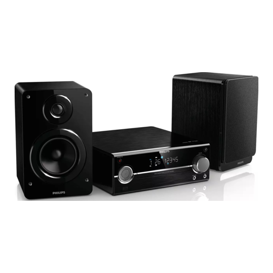
Micro Audio System
Contents
.................................................1-1 to 1-9
2 Laser Beam Safety Precautions......................................... 2-1
3 Important Safety Precautions .................................. 3-1 to 3-2
4 Safety Check After Servicing ............................................. 4-1
Requirements .................................................................... 5-1
7 Direction of Use ....................................................... 7-1 to 7-4
8 Cabinet Disassembly Instructions ........................... 8-1
9 Troubleshooting ....................................................... 9-1 to 9-2
10 Block Diagram .................................................................10-1
11 Wiring Diagram ...............................................................11-1
12 AMP Board
Circuit Diagram ...................................................12-1
Layout Diagram ...................................................12-2
13 Display Board
Circuit Diagram ................................................12-3
Layout Diagram ...............................................12-4
14 USB and Headphone Board
Circuit Diagram .................................................12-5
Layout Diagram..................................................12-5
© Copyright 2012 Philips Consumer Electronics B.V. Eindhoven, The Netherlands.
All rights reserved. No part of this publication may be reproduced, stored in a
retrieval system or transmitted, in any form or by any means, electronic,
mechanical, photocopying, or otherwise without the prior permission of Philips.
Published by SW-KM 1212 AVM
Version 1.0
Page
15 Power Board
16 Decoder Board
17 Exploded View...................................................................13-1
18 Revision List .......................................................................14-1
Printed in the Netherlands
Contents
Circuit Diagram .....................................12-6 to 12-7
Layout Diagram ............................................... 12-8
Circuit Diagram ................................... 12-9 to 12-12
Layout Diagram ............................................... 12-13
Features
RDS
Voltage Selector
ECO Standby
DTS
Subject to modi cation
MCD785/51
Page
Feature
Different /51
EN
3141 785 37680
Advertisement
Table of Contents

Related Manuals for Philips MCD785/51


Summary of Contents for Philips MCD785/51
-
Page 1: Table Of Contents
Feature Different /51 Features © Copyright 2012 Philips Consumer Electronics B.V. Eindhoven, The Netherlands. All rights reserved. No part of this publication may be reproduced, stored in a Voltage Selector retrieval system or transmitted, in any form or by any means, electronic, ECO Standby mechanical, photocopying, or otherwise without the prior permission of Philips. -
Page 2: Technical Specification And Connection Facilities
Technical Specification and Connection Facilities 1.Location of PC Boards Decoder Board AMP Board DVD Loader Power Board Display Board USB Board Headphone Board Version Variations Type /Versions: MCD785 Service policy Board in used: AMP Board Decoder Board Display Board Power Board USB Board Headphone Board Type /Versions... - Page 3 Identity and Key Features MCD785 is a Micro DVD Audio System support external iPod docking station, CD/DVD player with USB and Tuner FM. It is Philips Heritage Range Series AVM product. Elements to include as generic requirements: 1. Detachable mains cord 2.
- Page 4 Technical Specification and Connection Facilities S-Video port Headphone Port √ (3.5mm audio jack) M-Boy port(3.5mm headphone jact) 2.1.4 ACCESSORIES Stroke Version Region Europe Power Cord 1.8M AV cable(Y color) 1.5M Audio cable 0.5M (3.5mm audio) Tuner Antenna 1.5M pigtail Speaker cable USB cable Remote Control 40keys...
- Page 5 Technical Specification and Connection Facilities Safety Standards Where applicable: For /12 (EU), /05 (UK), /51 (Russia) EN/IEC 60065 7 Edition For /37 (US, Canada) UL 60065 Edition For /55 (LATAM), /78 (Brazil) IEC 60065 7 For /98 (AP), /69 (Singapore), /75 (Australia) IEC 60065 7 Edition For /93 (China)
- Page 6 Technical Specification and Connection Facilities Environmental Condition The environmental condition requirements and test method is according to UAN-D1590. Ambient temperature : max. 40 ° C - all climates Apparatus acc. to spec. : +5 to + 35 ° C Vibration test (acc. IEC 60 068/2/6) : operational vibration test to be proceeded in operating position of the set.
- Page 7 Technical Specification and Connection Facilities From +/3kV to +/-6kV in steps of 1 kV. 10 shots per combination. One shot per minute. Serial impedance: 2 Ohm for Europe, 12Ohm for Nafta Polarity and phase: Positive (phase 90º) & Negative (phase 270º) Reference: IEC61000-4-5 and for USA: 3135 019 8029 Reliability evaluation.
- Page 8 Technical Specification and Connection Facilities Audio 3.2.1 Analog Audio Input/Outputs Output Stage Protection: Temperature : Short Circuit: v i t Electrical Data ± 3dB --- Vol -20dB 150nW i n i : e l < ≥82dBA : k l ≥55dB Audio Inputputs Audio Output(*1) Audio Input Sensitivity(±...
- Page 9 Technical Specification and Connection Facilities 3.2.2 Digital Audio Outputs Type Standard CDDA / LPCM (including MPEG1) IEC60958 MPEG2, Dolby Digital (AC-3) IEC61937 DTS, 96kHz 24 bit 3.2.2.1 Coaxial Description Specification Output signal amplitude 0.5 Vpp ± 20% Output impedance 75 Ω ± 20% DC output voltage <...
- Page 10 Technical Specification and Connection Facilities 3.3.1.2 Component Video (Y/Pb/Pr) (NA) Description Test Signal Specification Interlace/Progressive NTSC i l p ± ± ± ± PbPr peak to peak 75% Color bar 525mV ± 10% 535mV ± 10% 75% Color bar PbPr Output unbalance ≤3% ≤3% i l p...
-
Page 11: Laser Beam Safety Precautions
Laser Beam Safety Precautions This Blu-Ray player uses a pickup that emits a laser beam. Do not look directly at the laser beam coming from the pickup or allow it to strike against your skin. The laser beam is emitted from the location shown in the figure. When checking the laser diode, be sure to keep your eyes at least 30 cm away from the pickup lens when the diode is turned on. -
Page 12: Important Safety Precautions
Do not insert warped or cracked discs into the disc compartment. the combined weight of the product and the wall mount. Koninklijke Philips Remove discs from the disc compartment if you are not using the product for an Electronics N.V. bears no responsibility extended period of time. - Page 13 Important Safety Precautions Disposal of your old product and batteries Your product is designed and manufactured with high quality materials and components, which can be recycled and reused. When this crossed-out wheeled bin symbol is attached to a product it means that the product is covered by the European Directive 2002/96/EC.
-
Page 14: Safety Check After Servicing
Safety Check after Servicing Examine the area surrounding the repaired location for damage or deterioration. Observe that screws, parts, and wires have been returned to their original positions. Afterwards, do the following tests and confirm the specified values to verify compliance with safety standards. 1. -
Page 15: Safety Information General Notes & Lead Free Requirements
Safety Information, General Notes & Lead Free Requirements Safety Instructions Warnings General Safety General Safety regulations require that during a repair: All ICs and many other semiconductors are susceptible to Connect the unit to the mains via an isolation transformer. electrostatic discharges (ESD, ). -
Page 16: Standard Notes For Servicing,Lead Free Requirements & Handling Flat Pack Ic
When soldering, be sure to use the Pb free solder. indicated as shown. Information about lead-free soldering Top View Bottom View Philips CE is producing lead-free sets from 1.1.2005 onwards. Input IDENTIFICATION Regardless of special logo (not always 2. For other ICs, pin 1 and every fifth pin are indicated) indicated as shown. - Page 17 2004), containing leaded solder-alloy and components, all needed spare-parts will be available till the end of the service-period. For repair of such sets nothing changes. On our website www.atyourservice.ce.Philips.com you find more Fig. S-1-1 information to: BGA-de-/soldering (+ baking instructions) 2.
- Page 18 Standard Notes for Servicing, Lead Free Requirements & Handling Flat Pack IC 3. The flat pack-IC on the CBA is affixed with glue, so 4. Release the flat pack-IC from the CBA using be careful not to break or damage the foil of each tweezers.
- Page 19 Standard Notes for Servicing, Lead Free Requirements & Handling Flat Pack IC Instructions for Handling Semi- 2. Installation conductors 1. Using desoldering braid, remove the solder from the foil of each pin of the flat pack-IC on the CBA Electrostatic breakdown of the semi-conductors may so you can install a replacement flat pack-IC more occur due to a potential difference caused by easily.
-
Page 20: Direction Of Use
The following excerpt of the DFU/QSG serves as an introduction to the set. The Complete Direction for Use can be download in different languages from the internet site of Philips Customer care Center : www.support.philips.com Overview of the main unit •... - Page 21 Direction of Use BACK Overview of remote control • Return to previous display menu. • In dock mode, enter the menu list. • Skip to previous or next title, chapter, track, or • In tuner mode, select programmed radio stations. •...
- Page 22 Direction of Use 3 Connect Hold down the socket flap. Insert the stripped part of the wire completely. • Insert the right speaker wires to " R ", left speaker wires to "L". • Insert the red wires to " + ", white wires Place the unit to "-".
- Page 23 • If this product connects to a TV compatible with 1080p or 1080p/24Hz, Philips recommends HDMI category 2 cable, also known as High Speed HDMI cable, for optimal video and audio output. • This type of connection provides the best picture quality.
-
Page 24: Cabinet Disassembly Instructions
Cabinet Disassembly Instructions 1. Disassembly Flowchart This flowchart indicates the disassembly steps to gain access to item(s) to be serviced. When reassembling, follow the steps in reverse order. Bend, route, and dress the cables as they were originally. Top Cover [1]. -
Page 25: Troubleshooting
Troubleshooting FLOW CHART NO.1 No sound from whole unit check and change speaker and output wire check if speaker is ok check if public circuit of whole unit check radio tube and periphery circuit AMP circuit is ok check and change transormer of power supply and check if power supply circuit of whole unit is ok power commutate circuit... - Page 26 Troubleshooting no search from DVD check if supply +12V of Decoding board is normal check steady circuit check if laser head ass'y can light normally Decoding board is broken check if tie wires of laser head ass'y check and change good laser head ass'y is loosen and broken laser head ass'y broken FLOW CHART NO.4...
-
Page 27: Block Diagram
Block Diagram D3.3V D1.2V CVBS PICK UP SONY CVBS DM-06BXLX-L2 Vc(Vref) COAXIAL VR-CD COAXIAL D3.3V VR-DVD CD/DVD SW VR-LD SDR_DRAM M12L64164A MPEG DVD-LD GND-PD GND-LD D3.3V MT1389DXE-G DVD Loader SERIAL-FLASH Motor Driver EN25F16 HDMI 5888S ESD REJECTOR & EMI VUSB HOST USB 2.0 D3.3V CEC BUFFER... -
Page 28: Wiring Diagram
Wiring Diagram AC220V Power Board CON3 CON5 CON6 AMP Board Decoder Board CON6 CON1 CON7 CON4 CN502 CN301 MUTE J502 CN401 Headphone Board AUX-L AUX-R J501 CN501 J401 USB Board 11-1 11-1... -
Page 29: Circuit Diagram
AMP Board -- Circuit Diagram FM_CP_RST DAB_MUTE R193 NC/330 R169 R170 IPOD/DAB_TX R194 NC/330 IPOD/DAB_RX C188 FB600 NC/0 P25V +12V 100P /RST 1 A5V MCU_5V R175 330/NC R179 0R/NC/NC SCL3 FB/600 MSCL SDA3 R173 330/NC FB/600 MSDA FM5V FM5V FB/600 TO MCU ROUT FM_INR... - Page 30 AMP Board -- Layout Diagram 12-2 12-2...
- Page 31 Display Board -- Circuit Diagram VFD301 S301 R306 2.2R 1/2W R305 2.2R 1/2W C309 R323 R324 L305 200UH R321 47R C311 C314 C313 -24V C312 470uf/16v 47uf/16v T902 Q301 D965 R379 100R C301 S12/KS12 S11/KS11 104M S10/KS10 R315 R381 100R S9/KS9 R319 1K DZ301...
- Page 32 Display Board -- Layout Diagram 12-4 12-4...
- Page 33 USB and Headphone Board -- Circuit and Layout Diagram Headphone Board USB Board J401 CN502 USB HOST 4P/2.0 CN401 J502-A PH-MUTE-1 GND-U HP-R-1 HP-L-1 VBUS VBUS AUX-R AUX-L CN501 J501 3P/2.0 SP-2JCK 12-5 12-5...
- Page 34 Power Board -- Circuit Diagram 1 222M/400V Lp=0.48mH UU10 .5-30mH T18*10*7mm 20mH 471M/400V +17.5V/3.5A 10uH/0.6mm 10A/150V 4*RL257 68K/2W 47uF/450V 47uF/450V 103P / 630V 104/50V/1206 2*680u F/25V R18/19/20/R21 102/1KV 1500u F/25V 4x120R/1206 471M/400V R30/R31 102/500V/1206 47R/1206 *2 KA78 L12 Vout +12V/0.5A 10uH/0.6mm CE13 D10/D9...
- Page 35 Power Board -- Circuit Diagram 2 9P/2.5 TO-6026 APM4800SOP-8 + 9-16 Vdc AF9435P PIN1,2,3 PIN5,6,7,8 80uH/0 .7mm PIN4 +17.5V +17.5V +20V/4A 1000u F/ 10V 2* 0.1R/1206 SB560 +12V/0.5A 1K/0805 D+5V/1.5A 10K/0805 MCU5V 47K/0805 C945 SOT-23 CON2 MC 34063 471pF/50V A733 SOT-23 12-7 12-7...
- Page 36 Power Board -- Layout Diagram 12-8 12-8...
- Page 37 Decoder Board -- Circuit Diagram 1 COMMON1389G_HD65_AT5669_V1.1 MT1389G (LQFP128) DVD Board w/ Sanyo HD6x Series PUHs Original release 2008.09.25 standby40-60mA V1.1 2009.02.17 1),Modify CE31 from 47uF to 220uF for power noise improve; Play 2),Add 100 ohm resistance R160 and R161 to XI and XO nets for tune DPD performance; DVD5V 570mA, 800mA...
- Page 38 Decoder Board -- Circuit Diagram 2 SANYO Crystal OFF-PAGE CONNECTION 89G_3V3 RFV12-1 HD6x/sony FB/200 89G_3V3 ADACVDD 100k 89G_3V3 4.7uF/10v 0603 DQ[0..15] L8 FB/100uH DQ[0..15] 0.1uF DACVDD3 DACVDD3 AADVDD 1R 0805 L9 FB BAT54C 0.1uF RFVDD3 XI XI XI MA[0..11] MA[0..11] 0.1uF 27MHz+_10PPM DQM[0..1]...
- Page 39 Decoder Board -- Circuit Diagram 3 OFF-PAGE CONNECTION ESMT M12L64164A 89G_3V3 SR_3V3 DQ[0..15] DQ[0..15] MA[0..11] MA[0..11] CE19 CB29 DQM[0..1] DQM[0..1] SR_3V3 100uF/6.3v 0.1uF BA[0..1] BA[0..1] SDCKE DCLK DCLK DCS# MA10 DQ10 RAS# A10/AP DQ10 RAS# MA11 DQ11 CAS# CAS# DQ11 DBA0 DQ12 SR_3V3...
- Page 40 Decoder Board -- Circuit Diagram 4 OFF-PAGE CONNECTION CVBS_OUT CVBS_OUT G/Y_OUT FB/0603/NC ASPDIF 100/NC COAXIAL 0.1uF/NC 100/NC 330pF/NC B/U_OUT ESD/NC GPIF32T/NC AVCC L23 1.8uH/SMD/NC CVBS_OUT VIDEO_DVD R/V_OUT R418 0/NC R419 33/NC ESD/NC SPDIF 75/NC GPIF32T TXC+ TXC+ 47pF/NC 47pF/NC TXC- TXC- AV3-8.4-14D/NC AV3-8.4-14D...
- Page 41 Decoder Board -- Layout Diagram 12-13 12-13...
-
Page 42: Exploded View
Exploded View Aluminual Top Cover S009 Back cover Screw Screw S006 Screw Screw PCB6 Dust cover PCB5 Standby Button S004 DVDM PCB1 S002、S003 PCB7 Screw S005 S001 S007 PCB2 Spring S008 PCB3 Plastic Foot Bottom cover Filter Lens ALU. Front Panel Screw Screw 13-1... -
Page 43: Revision List
Revision List Revision List Version 1.0 * Initial Release 14-1...