
Related Manuals for X-TREME Rubicon 48V


Summary of Contents for X-TREME Rubicon 48V
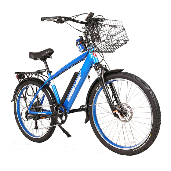
- Page 1 Rubicon 48V / Sedona 48V Santa Cruz 48V / Catalina 48V Baja 48V Rocky Road 48V Owner’s Manual www.ElectricBicycle.com...
-
Page 2: Important Information
PLEASE READ PRIOR TO RIDING IMPORTANT INFORMATION FULLY CHARGE BATTERIES BEFORE FIRST USE - Batteries should be fully charged immediately when they are received and immediately after each use for the recommended charge times (see below) • Li-Po4 Lithium Batteries: 4-6 hours FACTORS TO MAXIMIZE THE RANGE OF YOUR ELECTRIC BICYCLE ... -
Page 3: Table Of Contents
TABLE OF CONTENTS Important Information………………………………………………………………………………………….. 2 Table of Contents……………………………………………………………………………………………… 3 Terminology & Battery Systems………………………………………………………………………………… 4 Required Tools………………………………………………………………………………………………… 5 Before You Ride……………………………………………………………………………………………….. 6-8 Safety Checklist………………………………………………………………………………………………..9-10 Bicycle Care…………………………………………………………………………………………………… 10-13 Basic Maintenance………………………………………………………………………………………… 10 Throttle…………………………………………………………………………………………………… 11 Battery Care and Information……………………………………………………………………………….. 11-2 Charger……………………………………………………………………………………………………12-13 Bicycle Assembly……………………………………………………………………………………………… 13 Getting Started…………………………………………………………………………………………….. -
Page 4: Terminology & Battery Systems
Warning / important - take notice of this symbol throughout this manual and pay particular attention to the instructions blocked off and preceded by this symbol. TERMINOLOGY POWER Systems – Pedal Assist - A sensor ring and pickup mounted near the bottom bracket allow the bicycle to sense forward pedaling and apply power. -
Page 5: Required Tools
Your new bicycle was partially assembled in the factory and then partially disassembled for shipping. You may have purchased the bicycle already fully assembled and ready to ride OR in the shipping carton in the partially disassembled form. The following instructions will enable you to prepare your bicycle for years of enjoyable cycling. -
Page 6: Before You Ride
BEFORE YOU RIDE ABOUT THIS MANUAL It is important for you to understand your new bicycle. By reading this manual before you go out on your first ride, you’ll know how to get better performance, comfort, and enjoyment from your new bicycle. It is also important that your first ride on your new bicycle is taken in a controlled environment, away from cars, obstacles, and other distractions. - Page 7 Seat Height RIDING POSITION In order to obtain the most comfortable riding position and offer the best possible pedaling efficiency, the seat height should be set correctly in relation to the rider’s leg length. The correct seat height should not allow leg strain from over-extension, and the hips should not rock from side to side when pedaling.
- Page 8 Stem Wedge Bolt Handlebar Adjustment & Height Handlebar The stem’s “Minimum insertion” mark must not be visible above Maximum Height/ Binder Bolt the top of the headset. If the stem is extended beyond this mark, Minimum the stem may break or damage the fork’s steering tube, which Insertion Mark Exceeds 2 1/2”...
-
Page 9: Safety Checklist
SAFETY CHECKLIST Before first initial ride and every ride after, it is important to carry out the following safety checks: 1. Brakes Ensure front and rear brakes work properly. Ensure brake calipers are not over worn and are correctly adjusted. ... -
Page 10: Bicycle Care
8. Frame and Fork Check that the frame and fork are not bent or broken. If either is bent or broken, they should be replaced. 9. Accessories Ensure that all reflectors are properly fitted and not obscured. ... -
Page 11: Throttle
18-22mph (30-35km/h). BATTERY CARE AND INFORMATION Proper maintenance of batteries will maximize their lifespan and capacity. X-Treme Scooters warranties your new batteries from the date of purchase for 1 full year when properly cared for. Visit http://support.x-tremescooters.com... -
Page 12: Charger
STORAGE When storing your batteries for a long period of time (longer than two months): • Charge your batteries every 90 days to avoid capacity loss. Batteries slowly self-discharge when left unused for a long period of time; if the battery cells are allowed to reach a critically low voltage, their lifespan and capacity will be permanently reduced. -
Page 13: Bicycle Assembly
**Note: Your bicycle may be equipped with different style components than the ones illustrated within this manual. We recommend that you contact X-Treme if you have doubts or concerns as to your experience or ability to properly assembly, repair, or maintain your bicycle... -
Page 14: Stem And Handlebars
STEM AND HANDLEBARS (STANDARD QUILL-TYPE Remove the protective shipping cap from the stem wedge. Remove the Stem Plug from the stem. Loosen the Stem Bolt with a 6mm allen wrench or 13mm box wrench. Insert the stem into the head tube of the bicycle. Ensure that the Minimum Insertion Line is below the top nut of the headset. - Page 15 WARNING: MINIMUM INSERTION LINE MUST BE HIDDEN WITHIN THE HEADTUBE OF THE BICYCLE. Stem should be inserted into the top nut of stem bolt at least. Binder Bolt if the stem is not inserted into the top nut to at least the stem bolt. Stem Bolt Minimum Top Nut...
- Page 16 Handlebar Wedge Head Tube Stem Installation (should be assembled on the bike already) Compression Bolt Insert the compression bolt through the top cap and the stem. Begin Top Cap threading into the star nut. Stem Cap Bolt Headset Wedge Tighten compression bolt so it removes all play from the fork, but allows Stem Clamp Bolts Bearing Dust Cover the fork to rotate smoothly.
-
Page 17: Front Forks
Should you attempt to install the forks on your own, we request you consult X-TREME SCOOTERS for assistance or seek Tech Support from the professionals at a local bike store. Please note that incorrect installation is extremely dangerous and can cause damage to your bicycle and/or possible injury or death to the rider. - Page 18 Very Important Information WARNING! Be sure to read carefully the instructions below before using your suspension fork. Inappropriate usage of your suspension fork may cause damage to the product and/or injuries or death to the rider. 1. Suspension forks contain fluid and gas under extreme pressure. Warnings included in these instructions must be followed in order to reduce the possibility of injuries and possible death.
- Page 19 4. Install the head set crown race (30mm for 1 1/8") firmly against the top of your fork crown. Install the fork unit (headset, spacers and stem) back on the bike. 5. Install brake and make sure to adjust the brake pads properly. If you use a disc brake, only mount your brake to the original disc brake mounting holes. Only use cantilever brakes which are intended to be used with a brace that does not have a hanger.
-
Page 20: Tektro Brakes
TEKTRO BRAKES INSTALLATION & ADJUSTMENT OF YOUR BRAKES The Caliper and rotor for the front and rear of the bike are the same. The only difference between front and rear disc brakes is which adapter should be used to mount the caliper to the bike. - Page 21 Cable Barrel Adjustment Note: Do not only adjust the cable tension to compensate pad wear. After replacing with new pads, check if the rotor and pad come in contact with each other. If so, you need to adjust step pads and caliper again. Warning:! 1.
-
Page 22: Shimano Altus Rear Derailleur
Shimano Altus Rear Derailleur • If gear shifting operations cannot be carried out smoothly, clean the derailleur and lubricate all moving parts. • If the amount of looseness in the links is so great that adjustment is not possible, you should replace the derailleur. •... - Page 23 Install of the Rear Derailleur Install the rear derailleur (A) 5mm Allen Wrench (B) Fork end (C) Bracket NOTE: Periodically check that there is no gap between the fork end and the bracket as shown in the illustration. If there is a gap between these two parts, problems with gear shifting performance may occur.
- Page 24 Stroke Adjustment No. 1 As shown in illustration No. 1 (A) Smallest Sprocket (B) Guide Pulley (C) “H” Adjustment Bolt Turn the “H” adjustment bolt to adjust so that the guide pulley is in line with the outer line of the smallest sprocket when looking from the rear.
- Page 25 Using the B-Tension Adjustment Bolt As shown in illustration No. 1 (A) Largest Sprocket (B) Smallest Sprocket (C) B-Tension Adjust Bolt Mount the chain on the chain ring and the largest sprocket and turn the crank arm for shifting. Adjust the B-tension bolt so that the guide pulley does not interfere with the sprocket but do not let the pulley come close to the chain that they come In contact with each other.
- Page 26 How to Take Up the Slack in the Cable As shown in the illustration (A) “A” Slot (Z) Pull Connect the inner cable to the rear derailleur as shown in illustration (A). Remove the initial slack from the cable as shown in the illustration (Z). Reconnect the cable to the derailleur and secure the cable in the slot.
-
Page 27: Kickstand
How to Adjust Rear Derailleur Step By Step 1. Loosen the bolt on derailleur and remove cable, afterwards check the finger shifter to be sure that finger shifter pointing at the figure No. 9. 2. Set the chain on the smallest gear sprocket and use screw driver to adjust "H" bolt (refer back to "H" adjustment bolt), keep in mind that when this setup is done, do not turn the "H"... -
Page 28: Rear Suspension
CAUTION! regular bolts replacement. Contact X-Treme Bicycle for replacement spare parts. Be sure to check the tightness of each bolt prior to riding your E-Bike. Make sure that these bolts are not loose PRIOR TO EACH RIDE. -
Page 29: Seat And Seat Post
SEAT AND SEAT POST Seat Fixing Bolt Your bicycle may come equipped with either a standard or a micro-adjustable seat post. Seat Clamp Nuts Standard seat post Attach the seat to the seat post by first loosening the nuts on the seat clamp. Insert the tapered Quick Release end of the seat post into the seat clamp until it is at the top of the clamp. -
Page 30: Installing Front Wheel
Figure 2 Figure 1 Figure 3 Figure 4 Figure 5 INSTALLING THE FRONT WHEEL Make sure the brakes are loose enough to allow the brake pads easily. Place wheel into fork drop outs (Figure 1). Insert Quick Release Axle (Figure 2) as shown in Figure 3 & 4 with nut. When axle is in place, push lever down on axle to lock into place (Figure 5). -
Page 31: Drivetrain
Drivetrain The drivetrain of a bicycle refers to all parts that transmit power to the rear wheel including the pedals, chain, chain wheel, crank set and freewheel. Pedals Pedals are available in a variety of shapes, sizes and materials and each are designed with a particular purpose in mind. -
Page 32: Troubleshooting
TROUBLESHOOTING PROBLEM POSSIBLE CAUSE REMEDY Low batteries Charge batteries for recommended time Faulty or old batteries Replace batteries Bicycle has reduced range and/or speed Low tire pressure Inflate tires to recommended pressure Brakes dragging against disc Adjust brakes and/or caliper Riding in hilly terrain, headwind, etc. - Page 33 Damaged wires Inspect all wires Charger shows a full charge in an Faulty charger Replace charger Faulty unusually short amount of time batteries Replace batteries Outlet has no power Check outlet for power Indicator light on charger not illuminated Blown fuse (Li-Po4 chargers) Replace fuse when charger is plugged into outlet Faulty charger...
-
Page 34: Specifications
48 VOLT SPECIFICATIONS SPECIFICATIONS Battery: 48V/8AH LiPo4 Lithium Battery, 52 cells Battery: 24V/8AH LiPo4 Lithium Battery, 14 cells Frame: Alloy 6061-T6, TIG welded Frame: Alloy 6061-T6, TIG welded Front Fork: Suntour Front Suspension Front Fork: Alloy suspension front fork Handlebar: Alloy, with adjustable alloy handlebar stem with scale Handlebar: Alloy, with adjustable alloy handlebar stem with scale... -
Page 35: How To Check Wire Terminals If Battery Not Charging Properly
How To Check Battery Terminals If Battery Not Charging Properly 1.) Remove battery pack from bike 2.) Remove cap from end of battery that has the Four Slots (Key end). 3.) Remove cover plate. 4.) You are now able to look at the Red and Black wires; the Two Black wires should be on the same side as the Key. 5.) If the Black wires are not on the side of the Key carefully open the Terminal Block Cover. -
Page 36: How To Replace Brake Lever
pad can be the difference between having a brake lever that feels spongy to one that is not.) How To Replace Brake Lever 1.) Loosen brake cable at caliper to gain slack in cable. 2.) Remove cable from brake lever 3.) Remove handlebar grip. -
Page 37: How To Replace Pedal Shaft
How To Replace Pedal Shaft (Left & Right is based on sitting on bicycle) Keep parts laid out in order for easier installment. Make yourself a drawing if needed and label each part when removed. 1.) Remove plastic pedal arm cover, that covers center shaft and nut and remove the nut and pull arm off of shaft. -
Page 38: General Information/Tech Support
DO NOT RETURN TO STORE! IF YOU NEED HELP CALL OR GO ONLINE 1-253-777-0690 http://support.x-tremescooters.com/ For General Information or Parts Visit www.x-tremescooters.com www.ElectricBicycle.com...