Advertisement
Quick Links
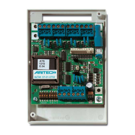
4/8-Zone DGP
M
OUNTING THE UNIT
The PCB can be mounted in any existing ATS series enclosure
that supports the BB format.Connections
J1
COMMS
12 VDC power supply. It is recommended that where
+
the distance between an ATS1220 and the nearest
-
device is more than 100 meters, a separate power
supply be used.
COMMS
Positive and negative data connection of the system
D+
databus. Units can be up to 1.5 km from the 4-lift
D-
DGP or the ATS control panel, depending on the
cable used. See the ATS control panel installation
guide for details.
T
TAMP
Connect the enclosure tamper switch across
C
these terminals (Tamper switch requires
normally open contacts.)
J2/J3
Each zones requires a 4k7 end-of-line resistor (1 or 2
depending on single or dual zone monitoring programmed
in ATS control panel).
J4
+12 VDC supply and open collector or data output for output
connection to ATS 1810, ATS 1811 and ATS 1820 output cards
via 10-way cable supplied with the output card. Up to sixteen
outputs are available with 8-way or 16-way open collector cards
(4-way and 8/16-way output cards cannot be used together
on the same DGP)
L
INKS
Earth connection. Earth wires from all pieces of
equipment must be earthed at one system earth.
For further detail see the ATS control panel
installation guide.
"I
./E
. T
NT
XT
INT
EXT
DGP
DIPSWITCH SETTINGS
ADDR
ABCT
T
A,C
B
Z
ONE NUMBERING
A 4/8-zones DGP can have four or eight zones connected to it.
There are 16 zones allocated to every DGP address. Only zones 1
to 4 or 1 to 8 can be used when an ATS1210/1211/1220 is
allocated a DGP number. Zones not available (5 - 16) or (8-16)
should be programmed as type 0 (zone disabled) in the Zone
database.
Control panel
DGP1
DGP2
DGP3
DGP4
DGP5
DGP6
DGP7
Note 1:The ATS1210/1211/1220 cannot be expanded to provide
additional zones.
© 2003 GE Interlogix B.V.
All Rights Reserved
ATS1210/1211/1220
4/8-Zone DGP
" J
S
AMP
UMPER
ETTINGS
Tamper switch SW4 + switch on backside SW5 of
the PCB are used (eg. in combination with ATS1644,
plastic housing).
Tamper connections on connector J1 (T, C) are
used for an external tamper switch (eg. In
combination with ATS1643, metal housing).
Dip switches 1 to 4 are used to identify the DGP
number.
Set switch T on if this device is the last device on the
system databus. For more details see the ATS
control panel installation guide.
Not in use
ON - ATS1811 8-way relay card or ATS1820 16-way
open collector card connected to J4.OFF - no
ATS1811 or ATS1820 connected to J4. Use this
setting also if an ATS1810 is connected to J4.
1 – 16
DGP8
17 - 32
DGP9
33 - 48
DGP10
49 - 64
DGP11
65 - 80
DGP12
81 - 96
DGP13
97 - 112
DGP14
113 - 128
DGP15
129 - 144
145 - 160
161 - 176
177 - 192
193 - 208
209 - 224
225 - 240
241 - 256
xxxxxxx
12/2004
Advertisement

Related Manuals for GE Aritech ATS1210


Summary of Contents for GE Aritech ATS1210
- Page 1 DGP7 113 - 128 DGP15 241 - 256 For further detail see the ATS control panel Note 1:The ATS1210/1211/1220 cannot be expanded to provide installation guide. additional zones. © 2003 GE Interlogix B.V. xxxxxxx All Rights Reserved 12/2004...
- Page 2 LED’ LED flashes to indicate the DGP is replying to polling from the ATS control panel. If the RX LED flashes but the TX LED does LED flashes to indicate polling data is being received on the not, it indicates that the DGP is not programmed to be polled system databus from the ATS control panel.
- Page 3 maximaal zestien outputs beschikbaar met 8-voudige relais of 16- NGANGSNUMMERING voudige open collectorkaarten (4-wegsvoudige en 8/16-wegsvoudige Aan een 4-ingangen DI kunnen 4 of 8 ingangen verbonden zijn. outputkaarten kunnen niet tegelijk op één DI gebruikt worden). Aan elk DI-adres zijn 16 ingangen toegewezen. Slechts de ingangen 1 –...
- Page 4 Non usati DGP2 33 – 48 DGP10 161 – 176 ON – Al connettore J4 sono collegate schede a 8 DGP3 49 – 64 DGP11 177 – 192 relè ATS1811 o la scheda a 16 uscite open collector DGP4 65 – 80 DGP12 193 –...
-
Page 5: Diody Led
Dioda LED błyska wskazując, że moduł MZD IODY odpowiada na odpytywanie z centrali ATS. Jeśli Dioda LED błyska wskazując, że są odbierane dane dioda LED RX błyska, lecz dioda LED TX nie błyska, odpytywania z centrali przez magistralę systemową. oznacza to, że moduł MZD nie jest zaprogramowany Jeśli dioda LED nie błyska, oznacza to, że centrala w centrali do odpytywania lub że jest nieprawidłowo nie działa lub że magistrala systemowa jest... - Page 6 TAMP Koble sabotasjebryteren for kapslingen over Ikke i bruk disse terminalene (Sabotasjebrytere krever ON - ATS1811 8-dobbelt relékort eller ATS1820 normalt åpne kontakter.) 16-dobbelt åpen kollektor-kort koblet til J4. OFF - ingen ATS1811 eller ATS1820 er koblet til J4. J2/J3 Bruk denne innstillingen også...
- Page 7 8 x eller 16 x open collector-kort (4 x og DGP7 113 - 128 DGP15 241 - 256 8/16 x udgangskort kan ikke bruges sammen på den samme Bemærk 1: ATS1210/1220 kan ikke udvides for at forøge antallet DGP). af zoner. INKS LED’ Jordtilslutning. Jordledninger fra alle udstyrsdele skal samles i en fælles jordledning.
- Page 8 241–256 vägskabeln som medföljer utgångskortet. Upp till 16 utgångar finns Obs! ATS 1210/1211/1220 kan inte byggas ut för att ge extra att tillgå med 4-vägs och 16-vägs open collector-kort (4-vägs och sektioner. 8/16-vägs utgångskort kan inte användas tillsammans på samma DGP).
- Page 9 “I ”-S Meldegruppen zugewiesen. Nur Meldegruppen 1 bis 4 oder 1 bis 8 TECKBRÜCKENEINSTELLUNGEN können verwendet werden, wenn eine ATS1210/1211/1220 einer Sabotageschalter SW4 + Schalter auf der Rückseite AME-Nummer zugewiesen ist. Nicht verfügbare Meldegruppen (5 - von SW5 der Platine werden verwendet 16) oder (8 - 16) sollten als Typ 0 (deaktivierte Meldegruppe) in (beispielsweise in Verbindung mit ATS1644- der Meldegruppendatenbank programmiert werden.
- Page 10 Vilkkuva LED-valo näyttää, että keskitin vastaa ATS- ERKKIVALOT keskuslaitteelta tulevaan pollaukseen. Jos RX-LED vilkkuu, Vilkkuva merkkivalo näyttää, että pollaustietoja mutta TX-LED ei, keskitintä ei ole ohjelmoitu keskuslaitteessa vastaanotetaan ATS-keskuslaitteelta järjestelmän dataväylän pollattavaksi tai sen osoite on määritetty väärin. kautta. Jos LED-valo ei vilku, keskuslaite ei ole toiminnassa tai dataväylä...
-
Page 11: Manufacturer's Declaration Of Conformity
Kelvinstraat 7 6003 DH Weert, The Netherlands Concerning 1.1.1. RTTE Safety Telecom A sample of the product Dare, GE Interlogix, Bicon Dare KTL-Telefication has been tested by: Test report reference QA plan : 00002 Version 2.18h EN50130-4(1995) +A1(1998) EN60950(1992) CTR21(1998) - Page 12 Technical specifications Specifications techniques Technische specificaties Specifiche tecniche Supply Voltage Tension d’alimentation Voedingsspanning Tensione di alimentazione 10,5 - 13,8V (Nominale) (12V ) Current consumption Consommation électrique Stroomverbruik Assorbimento 53 mA max. Dimensions (H x W) Dimensions (H x l) Afmetingen (H xB) Dimensioni (h x l) 90 x 80 mm (size B board).