Table of Contents
Advertisement
Available languages
Available languages
Quick Links
Owner's Manual
PDU & Maintenance
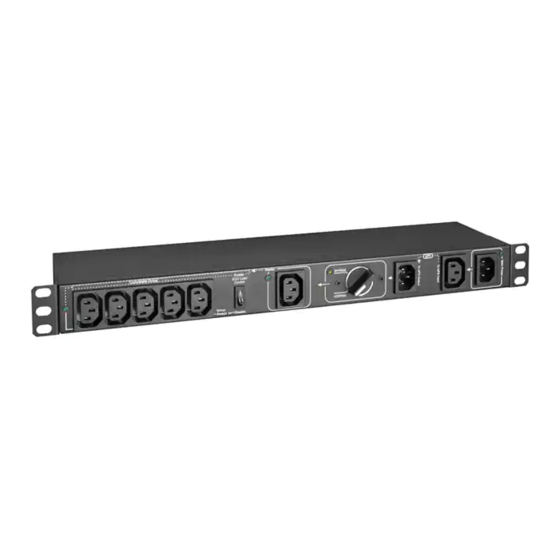
Bypass Switch Module
PDUB151U (Series Number: AG-0514)
PDUB201U (Series Number: AG-0515)
PDUBHV101U (Series Number: AG-0516)
PDUBHV201U (Series Number: AG-0517)
PDUBHV20B (Series Number: AG-0518)
PDUBHV20D (Series Number: AG-0519)
1. Introduction
2. Product Overview
3. Important Safety Warnings
4. Installation
5. Warranty & Product Registration
Español 9 • Français 17 • Русский 25
WARRANTY REGISTRATION
Register your product today and be
automatically entered to win an ISOBAR
surge protector in our monthly drawing!
tripplite.com/warranty
1111 W. 35th Street, Chicago, IL 60609 USA • tripplite.com/support
Models:
®
Copyright © 2020 Tripp Lite. All rights reserved.
1
2
2
4
4
8
Advertisement
Table of Contents

Related Manuals for Tripp Lite AG-0514 Series

Summary of Contents for Tripp Lite AG-0514 Series
- Page 1 WARRANTY REGISTRATION Register your product today and be automatically entered to win an ISOBAR ® surge protector in our monthly drawing! tripplite.com/warranty 1111 W. 35th Street, Chicago, IL 60609 USA • tripplite.com/support Copyright © 2020 Tripp Lite. All rights reserved.
- Page 2 1. Introduction This product is used as an external power distribution unit in conjunction with UPS systems. It enables the user to manually transfer the connected equipment to utility power via a bypass switch, permitting scheduled maintenance or UPS replacement without interruption of connected equipment.
- Page 3 2. Product Overview Master Output Receptacle(s) UPS-supported outlet with optional current sense capability. This connection is labeled MASTER on the Bypass PDU. Controllable Output Receptacle Group UPS-supported outlets with optional power switching capability. These connections are labeled CONTROLLABLE GROUP on the Bypass PDU.
- Page 4 3. Important Safety Warnings CAUTION! Save these instructions. To safely operate this unit, read and follow all instructions carefully. Read this manual thoroughly before attempting to unpack, install or operate. Retain this manual for further reference. • The unit is for indoor use only. •...
- Page 5 4. Installation Connect UPS 1. Connect the UPS input cord to the outlet for UPS input power cord (4). This outlet is labeled “To UPS Input” on the Bypass PDU. 2. Connect the protected UPS input power connection on the Bypass PDU to a protected UPS outlet. This connection is labeled “To UPS Output”...
- Page 6 4. Installation Plug Computer into Controllable Output Receptacle Computer Plug Peripherals into Controllable Output Receptacle Group Monitor Printer Switch Normal/Bypass Mode Operation Before transferring to maintenance bypass, make sure the Main Power LED is illuminated. Transfer the rotary bypass switch from NORMAL to BYPASS.
- Page 7 4. Installation Status Indicator Table ECO Mode Disabled ECO Mode Enabled Any load level Master load above threshold Master load below threshold Load Level Mains Available Transfer Normal Bypass Normal Bypass Normal Bypass Normal Bypass Normal Bypass Normal Bypass Switch Position Mains AC Green Green...
- Page 8 2-YEAR LIMITED WARRANTY TRIPP LITE warrants its products to be free from defects in materials and workmanship for a period of two (2) years from the date of initial purchase. TRIPP LITE’s obligation under this warranty is limited to repairing or replacing (at its sole option) any such defective products. To obtain service under this warranty, you must obtain a Returned Material Authorization (RMA) number from TRIPP LITE or an authorized TRIPP LITE service center.
-
Page 9: Table Of Contents
2. Vista General del Producto 3. Advertencias Importantes de Seguridad 4. Instalación 5. Garantía English 1 • Français 17 • Русский 25 1111 W. 35th Street, Chicago, IL 60609 EE UU • tripplite.com/support Copyright © 2020 Tripp Lite. Todos los derechos reservados. -
Page 10: Pdub151U (Número De Serie: Ag-0514)
1. Introducción Este producto se usa como una unidad de distribución de energía externa en conjunto con sistemas UPS. Permite al usuario transferir manualmente el equipo conectado a la energía de la red pública mediante un switch de derivación, permitiendo el mantenimiento programado o reemplazo del UPS sin interrupción del equipo conectado. - Page 11 2. Vista General del Producto Tomacorriente(s) Maestro(s) de Salida Tomacorriente soportado por el UPS con capacidad opcional de detección de corriente. Esta conexión está etiquetada como MASTER en el PDU de Derivación. Grupo de Tomacorrientes Controlables de Salida Tomacorrientes soportados por el UPS con capacidad de alternar entre las opciones de alimentación. Estas conexiones están etiquetadas CONTROLLABLE GROUP [Grupo Controlable] en el PDU de Derivación.
-
Page 12: Advertencias Importantes De Seguridad
3. Advertencias Importantes de Seguridad ¡PRECAUCIÓN! Conserve estas instrucciones. Para operar con seguridad esta unidad, lea y siga cuidadosamente todas las instrucciones. Lea cuidadosamente este manual antes de intentar desempacar, instalar o operar. Conserve este manual para referencia adicional. • La unidad se diseñó para uso exclusivo en interiores. •... - Page 13 4. Instalación Conecte el UPS 1. Conecte el cable de entrada del UPS al tomacorriente para el cable de alimentación del UPS (4). Este tomacorriente está etiquetado “a entrada de UPS” en el PDU de derivación. 2. Conecte la conexión de alimentación protegida del UPS en el PDU en derivación a un tomacorriente protegido del UPS. Esta conexión está...
- Page 14 4. Instalación Enchufe la Computadora en un Tomacorriente de Salida Controlable Computadora Enchufe los Periféricos en un Grupo de Tomacorrientes de Salida Controlables Monitor Impresora Switch Operación en Modo Normal / Derivación Antes de transferir a derivación para mantenimiento, asegúrese de que el LED de alimentación principal esté encendido. Transfiera el switch rotativo de derivación de NORMAL a BYPASS.
- Page 15 4. Instalación Tabla de Indicador de Estado Modo ECO Desactivado Modo ECO Activado Nivel de Cualquier nivel de carga Carga maestra superior al umbral Carga maestra inferior al umbral Carga Energía de la Red Pública Sí Sí Sí Sí Sí Sí...
-
Page 16: Garantía
GARANTÍA LIMITADA POR 2 AÑOS TRIPP LITE garantiza durante un período de dos (2) años a partir de la fecha de compra inicial que este producto no tiene defectos de materiales ni de mano de obra. La obligación de TRIPP LITE bajo esta garantía está limitada a la reparación o reemplazo (a su entera discreción) de cualquier producto defectuoso. - Page 17 2. Aperçu du produit 3. Avertissements importants en matière de sécurité 4. Installation 5. Garantie English 1 • Español 9 • Русский 25 1111 W. 35th Street, Chicago, IL 60609 USA • tripplite.com/support Droits d'auteur © 2020 Tripp Lite. Tous droits réservés.
- Page 18 1. Introduction Ce produit est utilisé comme une unité de distribution de puissance externe en conjonction avec des onduleurs. Il permet à l'utilisateur de transférer manuellement l'équipement connecté vers le courant du secteur par le biais du commutateur de dérivation, permettant l'entretien prévu ou le remplacement de l'onduleur sans aucune interruption de l'équipement connecté. La fonctionnalité...
- Page 19 2. Aperçu du produit Prise(s) de sortie maître(s) Prise prise en charge pour l'onduleur avec capacité de détection de courant en option. Cette connexion est étiquetée MASTER (maître) sur la PDU de dérivation. Groupe de prises de sortie contrôlable Prises prises en charge par l'onduleur avec capacité de commutation de l'alimentation en option. Ces connexions sont étiquetées CONTROLLABLE GROUP (groupe contrôlable) sur la PDU de dérivation.
- Page 20 3. Avertissements importants en matière de sécurité MISE EN GARDE ! Conserver des instructions. Pour un fonctionnement en toute sécurité de cet appareil, lire et respecter attentivement toutes les instructions. Lire complètement ce manuel avant de tenter de le déballer, de l'installer ou de l'utiliser. Conserver ce manuel à des fins de référence ultérieure. •...
- Page 21 4. Installation Raccordement de l'onduleur 1. Raccorder le cordon d'entrée de l'onduleur à la prise pour le cordon d'alimentation d'entrée de l'onduleur (4). Cette prise est étiquetée « To UPS Input » (vers l'entrée de l'onduleur) sur la PDU de dérivation. 2.
- Page 22 4. Installation Raccordement de l'ordinateur à la prise de sortie contrôlable Ordinateur Raccordement des périphériques à un groupe de prises de sortie contrôlables Moniteur Imprimante Commutateur Fonctionnement en mode normal/de dérivation Avant de passer en mode de dérivation d'entretien, s'assurer que le voyant à DEL Main Power (alimentation principale) est allumé.
- Page 23 4. Installation Tableau des voyants d'état Mode ECO désactivé Mode ECO activé Niveau de charge Tout niveau de charge Charge maître au-delà du seuil Charge maître de deçà du seuil Secteur disponible Position du commutateur de Normal Dérivation Normal Dérivation Normal Dérivation Normal Dérivation Normal Dérivation Normal Dérivation transfert Voyant à...
- Page 24 GARANTIE LIMITÉE DE 2 ANS TRIPP LITE garantit que ses produits sont exempts de vices de matériaux et de fabrication pendant une période de deux (2) ans à partir de la date d'achat initiale. La responsabilité de TRIPP LITE, en vertu de la présente garantie, se limite à la réparation ou au remplacement (à...
-
Page 25: English 1 • Français 17 • Русский
2. Kраткое описание изделия 3. Важные предупреждения по технике безопасности 4. Установка 5. Гарантийные обязательства English 1 • Español 9 • Français 17 1111 W. 35th Street, Chicago, IL 60609 USA • tripplite.com/support Охраняется авторским правом © 2020 Tripp Lite. Перепечатка запрещается. - Page 26 1. Введение Данное изделие используется в качестве внешнего блока распределения питания совместно с ИБП. Оно позволяет пользователю вручную переводить подключенное оборудование на питание от сетевого источника с помощью переключателя байпаса, что обеспечивает возможность проведения планового техобслуживания или замены ИБП без прекращения подачи электропитания к подключенному оборудованию. Дополнительная...
- Page 27 2. Kраткое описание изделия Глав. вых. разъем(-ы) Розетка с поддержкой от ИБП с дополнительной возможностью замера тока. Данный разъем обозначен как MASTER ("ГЛАВНЫЙ") на PDU обходной цепи. Управляемая группа выходных розеток Розетки с поддержкой от ИБП с дополнительной возможностью переключения питания. Эти разъемы обозначены как CONTROLLABLE GROUP ("УПРАВЛЯЕМАЯ ГРУППА") на...
- Page 28 3. Важные предупреждения по технике безопасности ВНИМАНИЕ! Сохраните настоящие указания. Для обеспечения безопасной эксплуатации данного блока следует ознакомиться со всеми инструкциями и тщательно выполнять их. Перед распаковкой, установкой или эксплуатацией изделия внимательно изучите настоящее руководство. Сохраните настоящее руководство для получения необходимой информации в будущем. •...
- Page 29 4. Установка Подключение ИБП Подключите входной шнур ИБП к розетке, предназначенной для входного шнура питания ИБП (4). Данная розетка обозначена как "To UPS Input" ("Ко входу ИБП") на PDU обходной цепи. Соедините защищенный входной разъем питания ИБП с защищенным выходным разъемом для подключения к ИБП, расположенным на PDU обходной цепи. Данный...
- Page 30 4. Установка Подключение компьютера к управляемой выходной розетке Компьютер Подключение периферийного оборудования к управляемой группе выходных розеток Монитор Принтер Переключатель (коммутатор) Нормальный режим работы / режим работы по обходной цепи Переключение в режим ремонтного байпаса должно производиться только при горящем светодиодном индикаторе "Main Power" ("Сетевое питание"). Переведите поворотный...
- Page 31 4. Установка Таблица индикаторов состояния Режим ECO отключен Режим ECO включен Нагрузка на главной розетке выше Нагрузка на главной розетке ниже Уровень нагрузки Любой уровень нагрузки максимально допустимой минимально допустимой Сетевое питание Да Да Нет Нет Да Да Нет Нет Да...
- Page 32 настоящей гарантии ограничиваются ремонтом или заменой (по ее единоличному усмотрению) любых таких дефектных изделий. Для получения услуг по данной гарантии необходимо получить номер Returned Material Authorization (RMA ― разрешение на возврат материалов) от компании TRIPP LITE или ее авторизованного сервисного центра. Изделия должны...