janitza UMG 804 User Manual And Technical Data
Bcm power analyser
Hide thumbs
Also See for UMG 804:
- User manual and technical data (40 pages) ,
- User manual and technical data (64 pages) ,
- Installation manual (36 pages)

Related Manuals for janitza UMG 804


Summary of Contents for janitza UMG 804
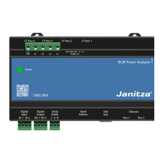
- Page 1 BCM Power Analyser UMG 804 User manual and technical data Fig. UMG 804 (24 V), optional Janitza electronics GmbH Vor dem Polstück 6 35633 Lahnau, Gemany Support tel. +49 6441 9642-22 E-mail: info@janitza.com www.janitza.com...
- Page 2 · This equipment must only be installed and serviced by qualified electrical personnel. · Do not use this product for life or safety For Janitza measurement devices and compo- applications. nents, use only current transformers intended for · Do not install this product in hazardous or measuring purposes (“transformers”)!
- Page 3 Information and specifications can be changed at any time. Please consult www.janitza.com for information on the current version. The English version is the original version of the documentation.
-
Page 4: Table Of Contents
4. Order information 5. Technical data 6. Features and Monitored Parameters 6. 1 Features 6. 2 Monitored Parameters 7. UMG 804 7. 1 Installation 7. 2 Connection of modules 8. DIN Rail CT Interface Floating Board (CTS24FBV) 8. 1 Overview 8. - Page 5 UMG 804 8. 3. 2 Bottom Feed 8. 3. 3 Single Row Sequential 8. 3. 4 Single Row Odd Even 8. 4 Application Example 9. DIN Rail CT Interface Card (CTC24CV) 9. 1 Overview 9. 2 Installation 9. 2. 1 Current Transformer Types 9.
- Page 6 Ping the Polling PC to establish IP Addressing 16. Appendix 16. 1 Spreadsheet Utility (firmware 1.126 or higher) 16. 2 Spanning Tree / Ring Topology 16. 3 Using POE power for the UMG 804 For firmware version 1.126 Earlier versions may not contain all the noted features.
- Page 7 UMG 804...
-
Page 8: General Information
· Metal or commission a certified disposal company with the scrapping. Copyright notice © 2019 - Janitza electronics GmbH - Lahnau. Safety All rights reserved. Any duplication, processing, distribution and any The safety chapter contain notes that must be other kind of use, even in part, is prohibited. -
Page 9: Danger Levels
UMG 804 Danger levels Read and understand the user manual before installation, operation, maintenance and use of the Warning notices and safety instructions are device. highlighted by a warning symbol and the danger levels are presented as follows depending on the... -
Page 10: Electrically Qualified Personnel
Janitza measurement devices or their compo- nents can lead to injuries and even death or to material damage! · Do not use Janitza measurement devices or components for critical switching, control or pro- tection applications where the safety of persons and property depends on this function. -
Page 11: System Overview
24 x 24 x 24 x 24 Fig.: DIN Rail CT Interface Boards connect to the Smart Ports on the UMG 804 using network cables. INFORMATION The UMG 804 can also be connected via Splitcore CT with Molex connector (available at Janitza electronics GmbH) -
Page 12: Order Information
Order information Article Short name Item no.: UMG 804 230 V AC UMG 804 14.02.001 UMG 804 230 V AC Advanced UMG 804 14.02.002 UMG 804 24 V DC UMG 804 14.02.009 UMG 804 24 V DC Advanced UMG 804 14.02.010... -
Page 13: Technical Data
UMG 804 Technical data General Device dimensions (approx.) w=158.7 mm, h=108.5 mm, d=59.2 mm (w=6.248 in, h=4.271 in, d=2.330 in) Transport and storage The following information applies to devices which are transported or stored in the original packaging. Temperature -40 °C to 70 °C (-40 °F to 158°... - Page 14 UMG 804 www.janitza.com Current measurement on modules Rated current 0 .. 600 A (external current transducer dependant) Resolution 0.01 A Crest factor 3.75 @ 100 % of 0.333 V signal Overload for 1 s 200 % Voltage measurement The voltage measurement inputs are suitable for measurements in the following power supply systems...
- Page 15 36 (1.420) 2,0 (78.74) 0.5* DIN-Rail * in combination with the UMG 804 and the DIN Rail CT Interface Floating Board / DIN Rail CT Interface Card Further information can be found in the separate data sheet for the current transformers.
-
Page 16: Features And Monitored Parameters
UMG 804 www.janitza.com Features and Monitored Parameters Features Standard Enhanced Feature / Version (v1.048 or lower) (v1.126 or higher) Supports 96 circuits using up to four interface cards • • Dual Ethernet ports • • Integrated webserver Original version •... - Page 17 UMG 804 · Alarming: provides alarms and status points with user-de- fined thresholds. · HTML interface: easy read/write access to all device configurati- ons and parameters. · Lock device settings: protection against manipulations. Especially use- ful for billing applications in data centers.
-
Page 18: Monitored Parameters
UMG 804 www.janitza.com Monitored Parameters Monitored Parameter Circuit Level Input Level Current per phase • • Max. current per phase • • Avg. Current per phase • • Current demand per phase • • Max. current demand per phase •... -
Page 19: Umg 804
Disconnect power to the panel or equipment to secure the enclosure in place. on which the monitor is being installed before starting the installation. Unlock The UMG 804 can be housed in existing enclosures where permitted by code or inside standard Lock electrical enclosures. DIN Circlips 7.5 mm... -
Page 20: Connection Of Modules
UMG 804 www.janitza.com Connection of modules The UMG 804 is installed by mounting on standard CAUTION 35 mm DIN rail. The enclosure can be mounted Note that the when the Ethernet cable is run in in any orientation. Secure the DIN rail using a... - Page 21 USB SD card on Advanced UMG 804s. The USB port can be used to confi gure the UMG 804 using a USB thumb drive with up to 32 GB in capacity the confi guration fi le. See the “Confi guration”...
- Page 22 ModBus Address “X” ModBus Address “X”+1 UMG 804 www.janitza.com PORT 1 PORT 2 PORT 3 PORT 4 STRIP 1 STRIP 2 STRIP 3 STRIP 4 Fig.: Cable Ports For circuit destination refer to „8.3 Panel Maps Confi guration“ on page 30 or „9.3 Panel Maps...
-
Page 23: Din Rail Ct Interface Floating Board (Cts24Fbv)
(Top Feed) or bottom facing (Bottom Feed). · Floating Boards also have slots that allow them to be zip tied in place instead of using DIN rail. · Ensure that the connections to the UMG 804 Smart Ports match those shown on the orienta- tion diagrams. - Page 24 Smart Port (RJ45 connector) top facing (Top Feed) or bottom facing (Bottom Feed). · The UMG 804 must be configured according to the selected orientation or else channels will not be aligned the panelboard pole numbers. This is...
-
Page 25: Current Transformer Types
UMG 804 8.2.1 Current Transformer Types 1. Plug the branch CTs into the polarized connectors on the Interface Board, refer to 2. Place the CT on the correct conduc- tor being sure to align the CT with the correct terminal and breaker conductor... - Page 26 UMG 804 www.janitza.com 4. Double check that the CTs are connected to the corresponding conductor. Use the CT Inter- face Board Orientation and Connection dia- gram for reference if needed (refer to chapter „8.2.3 DIN Rail CT Interface Board Orientation“ on page 38.
-
Page 27: Extensions Of Ct Wires
1 and 3 to be consistent. · Note that polarity and orientation of the CTs will be automatically corrected. · Note that versions of the UMG 804 can use the Virtual Meter function to accurately total the branch circuits eliminating the need for main input CTs. - Page 28 UMG 804 www.janitza.com IMPORTANT: Observe which CT strip auxiliary terminal blocks are designated for the main inputs. This will change depending on how the panels are configu- red. i.e. TOP FEED, BOTTOM FEED etc. Main CTs PANEL 1 Main CTs PANEL 2...
-
Page 29: Status Led
UMG 804 8.2.4 Status LED · Once energized the status LED on each strip will indicate proper operation. · This can also be confirmed on the Main Status page of the HTML console under the respective Smart Port settings „16.1 Main Status Page“ on page 49. -
Page 30: Panel Maps Configuration
UMG 804 www.janitza.com Panel Maps Configuration 8.3.1 Top Feed... - Page 31 UMG 804 PANEL 2 PANEL 1...
-
Page 32: Bottom Feed
UMG 804 www.janitza.com 8.3.2 Bottom Feed... - Page 33 UMG 804 PANEL 2 PANEL 1...
-
Page 34: Single Row Sequential
UMG 804 www.janitza.com 8.3.3 Single Row Sequential... - Page 35 UMG 804 PANEL 2 PANEL 1...
-
Page 36: Single Row Odd Even
UMG 804 www.janitza.com 8.3.4 Single Row Odd Even... - Page 37 UMG 804 PANEL 1 PANEL 2...
-
Page 38: Application Example
CT strip with the UMG 804. Auxiliary CT Terminal Block: monitors up to UMG 804: hosts up to four interface fl oating three auxiliary CTs per DIN Rail CT Interface boards. Floating Board, typically used to monitor main input circuits. -
Page 39: Din Rail Ct Interface Card (Ctc24Cv)
Card with the Smart Port (RJ45 connector) top facing (Top Feed) or bottom facing (Bottom Feed). · Ensure that the connections to the UMG 804 Smart Ports match those shown on the orienta- tion diagrams. · Smart Ports hosting the Interface Card must be correctly set in the HTML console under Con- figuration>General Settings. -
Page 40: Installation
Current Transformer Types LINE SIDE The DIN Rail CT Interface Card is designed to used 0.33 V output CTs provided by Janitza. Other 0.33 V CTs won`t work, Janitza does not warranty the performance if third party CTs are used. -
Page 41: Panel Maps Configuration
9.3.1 Sequential There are four Smart Port connectors (RJ45) on the UMG 804 that can host interface cards. The Smart Port receptacle selected for the card will affect how circuit numbers are referenced on that card. Channel numbers are cumulative so the card... - Page 42 UMG 804 www.janitza.com...
-
Page 43: Voltage Input /Electrical Connections
Failure to follow these instructions will result in death or serious injury. The UMG 804 must be connected to the voltage source being monitored. The Voltage Input termi- nal serves as the both power supply to the monitor and voltage sensing (230 V version). -
Page 44: Acceptable Wiring Configurations
UMG 804 www.janitza.com 10.2 Acceptable wiring confi gurations The monitor may be connected to any wiring confi guration shown in the following fi gure except for corner grounded delta circuits. Corner-grounded 4-Wire Wye 3-Wire 2-Wire 2-Wire 120/240V 3-wire (ungrounded) Delta - NOT ALLOWED... -
Page 45: 11. Serial Communications
UMG 804 11. Serial Communications The UMG 804 supports both Modbus TCP/IP and Modbus RTU serials communications. Connect the shielded 2 wire cable to the 2-wire Modbus RS-485 network with the serial interface jack. Mechanically secure the RS-485 cable(s) where USB PORT they enter the electrical panel. -
Page 46: 12. Ethernet Communications
UMG 804 www.janitza.com 12. Ethernet Communications can be used to link additional UMG 804s or other The UMG 804s equipped with dual managed third party Ethernet devices to the network. To Ethernet ports. Either port can be used to com- confi gure the IP settings see the confi guration at municate with the device. -
Page 47: 13. Confi Guration
UMG 804 13. Confi guration The UMG 804 can be confi gured in three different 2. Prepare the confi guration fi le. ways: If required, rename the confi guration fi le to “confi g.csv” 1. Via the USB Interface using a USB Flash Drive 3. -
Page 48: 14. Device Homepage
3. Use the default login of “admin” and default password of “admin”. This may be changed as required. 4. If the web console of the UMG 804 does not appear, ping the IP address using the windows command line prompt “ping 192.168.5.77” to... -
Page 49: Main Status Page
UMG 804 14.1 Main Status Page · The Main Status Page indicates the identifying features of the UMG 804 including firmware ver- sion and connectivity status to interface devices connected to the Smart Ports. BCMS Main Hall BCMS Main Hall 1.126... -
Page 50: Date And Time Reference
UMG 804 www.janitza.com 14.1.1 Date and Time Reference · The Date and Time can be synchronized by clicking on the Date button in the Main Status page. · This reference may be changed in the config.csv file or on the Homepage to reference the desired NTP server. -
Page 51: Smart Port Connectivity Status
UMG 804 14.1.2 Smart Port Connectivity Status The connection status of each module is visuali- zed on the homepage and via a status LED on the module. Status on Homepage The designated Smart Port (1-4) will display as CONNECTED on the Main Status page. -
Page 52: Network
· The factory default IP is always 192.168.5.77 · The PC or device must be set to the same subnet Ethernet as the IP address on the UMG 804 (see modify- Serial ing subnet (i.e 192.168.5.XXX) on PC for more details). -
Page 53: Serial Communications Settings
UMG 804 14.2.2 Serial Communications Settings · The Serial Settings page allows for all serial-ba- Ethernet sed settings to be configured. These settings Serial may also be configured using the config.csv file via USB drive or using Modbus write commands. -
Page 54: Data Menu
UMG 804 www.janitza.com 14.3 Data Menu The options under the Data menu allow for view- ing real time readings as well as waveform captu- res and voltage abnormalities. · Meter Data: Displays data for “True Meters” and „Virtual Meters“. True Meters are circuits that are grouped to represent a single circuit breaker such as a 2P or 3P breaker. -
Page 55: True Meter Data Page
UMG 804 14.3.1 True Meter Data Page · The Meter data page provides an overview of all data for all True Meters and Virtual Meters. True Meters are groups of individual circuits that are combined to represent a single two-phase or three-phase circuit breaker allowing total data for the breaker to be presented. - Page 56 UMG 804 www.janitza.com Current Alarm Settings · Over and under current alarms thresholds are set separately for True Meters and Virtual Meters than for individual circuit channels not assigned a “meter number” which are set on the Detailed Data page.
-
Page 57: Detail Data
UMG 804 14.3.2 Detail Data · The Detail Data page presents readings for all channels / circuits connected to the meter. · Channels are organized according to the Smart Port on the meter they are connected to. · The channel-to-circuit relationship will change according to how the Smart Ports are configured. - Page 58 UMG 804 www.janitza.com Setting Alarm Thresholds · Alarm thresholds can be set on the Detail Data page under the Data Menu. · Voltage thresholds are set using the Update Set- tings button under the Voltage Alarm. INFORMATION Setting any threshold to “0” will disable the alarm.
-
Page 59: Digital I/O Data
UMG 804 14.3.3 Digital I/O Data · The UMG 804 has two Digital Inputs and two Digital Outputs. The state of these can be seen on the Digital I/O Data page. · The Digital Outputs state change be toggled on this page. - Page 60 UMG 804 www.janitza.com · When a 24 Channel Digital Input Card (dry con- tact) is plugged into a Smart Port, the status of each of the 24 inputs will be shown on the Digital I/O Data page under the specific Smart Port the Card is plugged into.
-
Page 61: Waveform Capture
UMG 804 14.3.5 Waveform Capture · The Waveform Capture function will capture up to six cycles (256 data points) of a waveform for all of the affected 96 channels in the event the voltage or current exceeds the waveform capture thresholds. - Page 62 UMG 804 www.janitza.com Viewing and Downloading · To view a waveform capture, select the capture from the drop down menu which uses the dd/ mm/yy/hh/mn/ss file name and then select the phase and circuit / channel from the drop down menu followed by selecting Add to plot.
-
Page 63: Busway Data
UMG 804 14.3.6 Busway Data Currently not available. -
Page 64: Voltage Events
UMG 804 www.janitza.com 14.3.8 Voltage Events · Any voltage event that violates the CBEMA / ITIC power quality window will be captured and writ- ten to the USB flash drive. · A USB drive must be installed in the meter (no larger than 32 GB) to capture events. -
Page 65: Configuration
Point Map: The monitor is capable of supporting different register maps. The standard register map is the UMG 804 Point Map that provides access to all of the features the module offers. System Voltage: Provide the nominal system voltage (line to line) for the source. If a line to neutral single-phase source is being used input the line to neutral voltage. - Page 66 UMG 804 www.janitza.com CT Strip Configuration · The UMG 804 must be configured according to the physical orientation of the DIN Rail CT Inter- face Boards in order to correctly represent the channel to circuit relationship. · The configuration is determined by the panelbo- ard type and numbering sequence;...
-
Page 67: Ct Size
UMG 804 14.4.2 CT Size · The CT (current transformer) size configuration setting provides current transformer nominal amperage values for all circuit positions. This is critical as it affects the scaling of currents. · All CTs used are 0.33 V output. -
Page 68: Breaker Size
UMG 804 www.janitza.com 14.4.3 Breaker Size · The breaker size configuration setting provides trip ratings for each circuit breaker on each circuit. It does not influence any readings and is only used in over and under current alarms and percent circuit capacity calculations. -
Page 69: Voltage Phase
UMG 804 14.4.4 Voltage Phase · The Voltage Phase Assignment assigns a voltage phase (L1, L2, L3) to each channel in the event non-sequential panel type or receptacle types are being used. · The default is L1-L2-L3 in sequential order. -
Page 70: True Meter
UMG 804 www.janitza.com 14.4.5 True Meter · True Meter Mapping allows individual circuits/ channels to be grouped as one, two or three phase meters and read as a single meter meter with total readings for the meter. · For example: if channels 1, 2, 3 are a three-phase... - Page 71 UMG 804 True Meter Assignement - Example · In the below example each channel / pole on a Register Base breaker is assigned a common True Meter num- True Meter Address Friendly Name ber (must be unique to that circuit) from 1-96.
-
Page 72: Virtual Meter
UMG 804 www.janitza.com 14.4.6 Virtual Meter · “Virtual Meters” sum a group of channels / cir- cuits to provide a single reading that is the sum of all the circuits. Virtual Meters can be used for generating: - Panelboard mains reading without the need for panel mains CTs. - Page 73 UMG 804 Configuring Virtual Meters · To create a Virtual Meter go to the “configuration” tab on the HTML interface and select “Virtual Meter”. · Using the Virtual Meter mapping template provi- de a common Virtual Meter number “1-96” for all the channels that are to be grouped to form the Virtual Meter.
- Page 74 UMG 804 www.janitza.com Reading Virtual Meter Data · To read Virtual Meter data go to the “Data” tab and select „Meter Data“ and “Virtual Meter”. · Enter the number of the virtual meter you want to read.
-
Page 75: Virtual Meter Breaker
UMG 804 14.4.7 Virtual Meter Breaker · The breaker size configuration is needed when alarming is used as the alarm threshold is based on a percentage of the breaker size. · Enter the breaker size in Amps on the applicable Virtual Meter number. -
Page 76: System (Firmware Update)
Save Settings to File on USB This function will download all of the configuration settings from the UMG 804 to a .csv file on a USB drive installed in the UMG 804. This can then be used to verify settings as well as duplicate settings on other UMG 804s. - Page 77 1. Update Firmware · Uploading firmware requires that the firmware be NOTE transferred to a USB drive on the UMG 804. This can be accomplished either by a direct trans- If the USB drive is not recognized during the fer of files from a PC to USB Drive or remotely update process, you may have to reboot the (requires version 1.126 or higher) if the USB drive...
- Page 78 UMG 804 www.janitza.com 5. Select “continue” - the process will take around 1. Access the HTML console of the UMG 804 30-60 seconds. using a browser and the IP address of the UMG 804. 2. Insert USB fl ash drive that contains unzipped fi les into the UMG 804 USB port.
- Page 79 (firmware version 1.126 or higher) · Place the USB flash drive with the “config.csv” file into the USB port of the UMG 804. Note that Configuration files can be remotely uploaded over the name of the file must not be modified from a network.This requires a USB drive to be present...
-
Page 80: 15. Troubleshooting
Windows type “ipconfig / all” and confirm that the PC subnet mask, subnet and gateway are all cor- · If the IP address of the UMG 804 is not known rect and that there are no conflicting IP addresses. place a USB drive in the UMG 804 after it has booted up and stabilized and wait 15 seconds. -
Page 81: Modifying Ip Addresses
UMG 804 15.3 Modifying IP Addresses · IP addresses need to be changed on each UMG 804 to make them unique after firmware is Ethernet uploaded to prevent conflicts from identical IP Serial addresses on the same network. · These will be interim IP addresses unless perma- nent addresses are available. -
Page 82: Modifying The Subnet (Windows 10)
4. Select the Ethernet adapter and right click to reveal the menu; then click on “Properties”. · If your PC fails to access the UMG 804 when directly plugged into a PC it could be a result of the PC not being on the same subnet as the UMG 804. -
Page 83: Ping The Polling Pc To Establish Ip Addressing
Subnet Mask as UMG 804. If the commu- nications are going through a Gateway in a net- work, the UMG 804 must be set to the correct Gateway or else it can be left blank. 2. Type “ping” _ followed by the IP address of the UMG 804 to see if the polling device is commu- nicating with the UMG 804. -
Page 84: 16. Appendix
Using the Configuration Spreadsheet Utility Direct Editing of Downloaded config.csv spreadsheets · The UMG 804 can be configured by using the Configuration spreadsheet utility which can be · The values config.csv spreadsheet may be di- loaded onto the UMG 804 via a USB flash drive rectly edited on the .csv file... -
Page 85: Spanning Tree / Ring Topology
POE using a POE splitter. · The nominal voltage for DC input is 24 V DC. · A POE port splitter is required to separate the Ethernet and DC feed. · Each UMG 804 uses 3 Watts of power. - Page 86 Janitza electronics GmbH Vor dem Polstück 6 35633 Lahnau, Germany Tel.: +49 6441 - 9642-0 E-mail: info@janitza.com info@janitza.com | www.janitza.com...