
Summary of Contents for Panasonic HUSSMANN SMED153
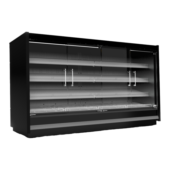
- Page 1 MEDIUM TEMPERATURE REMOTE CABINET SMED SEMI VERTICAL DISPLAY DOOR CABINET INSTALLATION MANUAL SMED153/163 JUN 2021 - AJHH9A20002A...
-
Page 2: Table Of Contents
CONTENTS CLEANING & MAINTENANCE GENERAL INFORMATION Commissioning Symbols Care & Cleaning Stop Think Act Daily Checks Staff Training Six Monthly Maintenance Electrical Connections Replacing Fan and Motor Blades Refrigerants Case Ventilation DECOMMISSIONING & DISPOSAL PRE-INSTALLATION Decommisioning Case Service Dimensions Disposal Operating Environment Handling and Transporting Cases Shipping Damages and Shortages... -
Page 3: General Information
GENERAL INFORMATION SYMBOLS: NOTE: NO CLIMB: Not related to personal injury Do not climb on top or on – Indicate[s] situations, which if not any parts of the case. This may cause avoided, could result in damage to damage to the case or personal injury. equipment CAUTION: NO CHEMICALS:... - Page 4 GENERAL INFORMATION SYMBOLS: TURN OFF: TECHNICIANS ONLY: Ensure that power source Installation is disconnected when conducting any should only be performed by qualified servicing or inspection. Injuries such technicians. as electric shock or burns could occur. NO FLAMMABLE: Do not expose the NO OBJECTS ON CASE: Do not case to any flamable objects.
-
Page 5: Stop Think Act
GENERAL INFORMATION STOP THINK ACT ELECTRICAL CONNECTION Check that the power supply voltage matches that displayed on the rating plate of the case, and that the STOP: Take the time to think about power is adequate. Voltage provided should be ±10% the installation process. - Page 6 GENERAL INFORMATION REFRIGERANTS TCO2/CO2: The refrigerant TCO2 & CO2 is a high pressure gas that is compatible with the environment, but is not flammable. Pay close attention during transport, installation and dismantling not to damage the refrigerant pipelines. CAUTION: Gas is under high pressure. EVENT OF DAMAGE: Keep surrounding flames or sources of ignition away from the appliance and gad.
-
Page 7: Case Ventilation
GENERAL INFORMATION LOCATION: NOTE: Check underside of case The refrigeration case should be positioned in a manner before lifting to ensure no damage to that optimal air flow can flow through the underside electrical, drain box or other extrusions and rear. This will minimise the risk of condensation on occurs. -
Page 8: Pre-Installation
PRE INSTALLATION CASE DIMENSIONS & SERVICES EXAMPLE SMED153 FIGURE 2A - EXAMPLE ONLY NOTE: This information is a reference only. Always refer to the latest Product Engineering Data sheet (PED). * SMED153/163 Case Dimensions found at back of the manual. PAGE 8 SMED SEMI VERTICAL - HUSSMANN... -
Page 9: Operating Environment
PRE INSTALLATION OPERATING ENVIRONMENT Cases have been factory tested to AS1731, +25 C at It is the responsibility of the transport company to 60% RH, and cross draft of maximum 0.2m/s. For insure adequate loading strategies are implemented to best performance, we recommend maintaining store insure the safe transportation of the Hussmann cases. -
Page 10: Shipping Damages And Shortages
PRE INSTALLATION HANDLING AND TRANSPORTING CASES The cabinets must be stored indoors, with a • Concealed loss or damage After removing all temperature ranging between 0 C and +40 C and a packing etc confirm with the parts list, attached to humidity between 30% RH and 90% RH. -
Page 11: Rating Plates
PRE INSTALLATION RATING PLATES: Each case has a 2 unique & 1 optional label that ASSET TAG (Where Applicable): includes an identification number. As well as on the packaging, the case identification number appears as a serial number on the rating plate (most commonly located on the ceiling panel left hand end of the case and left side rear panel) and is printed on a decal on the rear of the case . - Page 12 PRE INSTALLATION PACKAGING TAG: RATING PLATE (Continued): • Model No: Identifies the model type (letters on left) • Anti-Sweat Current: The heater thats installed as well as the model size (numbers on right) in the frames and doors of refrigerated cases to •...
-
Page 13: Installation
INSTALLATION POSITIONING AND LEVELLING Unwrap the cabinet and remove the shipping braces. NOTE: Information in this manual Lift up cabinet and remove shipping base. is to be followed in conjunction with specifications, work practices and regulations of the customer, installing company and relevant industry. - Page 14 INSTALLATION POSITIONING AND LEVELLING NOTE: It is important that all cases are Level Front to Back level for correct case joining and operation and door alignment. DO NOT SET CASE LEVELS OFF THE PATCH END fitted to a case Make sure case is level: Front to Back: +/- 1.5mm Side to Side: +/- 1.5mm (Figure 3C) NOTE:...
- Page 15 INSTALLATION Example of a 2500mm case - The amount of legs will defer on a each size case. Make sure all feet are adjusted, NOT just the ones at the end of the Make sure case is level: case, ensuring case load is fully supported. Front to Back: +/- 1.5mm FIGURE 3E Side to Side: +/- 1.5mm...
-
Page 16: Door Saw Toothing
INSTALLATION DOOR SAW TOOTHING SCHOTT DOOR : BENTCAM DOOR: The doors in the images below show the misalignment (saw toothing) . This should be completely horizontal NOTE: IF SAW TOOTHING OF DOORS and flush with each other. The door system on this IS EVIDENT THEN IT IS HIGHLY LIKEY case only has a minor adjustment. -
Page 17: Door Adjustment
INSTALLATION DOOR ADJUSTMENT: If the doors do not align horizontally, they can be adjusted using the adjustment mechanism in the sill rail. Check the vertical gap between the doors , to be Slide adjusted and the adjacent sets of doors, to see which door is the one to be adjusted. - Page 18 INSTALLATION DOOR ADJUSTMENT: BENTCAM DOOR : Cancelling Bentcam door misalignment is basically similar to the Schott door with this difference that hinge mechanism is at the bottom of the door assembly. FIGURE 3P Doors after adjustment and cancelling of misalignment FIGURE 3N Adjust the door by using of the two screws of door hinge plate at the bottom of door assembly.
-
Page 19: Lighting
INSTALLATION LIGHTING Single Row Canopy LED lighting is standard. Various optional shelf LED lighting is available and where fitted is located under each of the shelves. NOTE: Vertical mullion lighting is standard with Bentcam doors. It is important that proper cable management is followed and cables are clipped in correctly. -
Page 20: Fitting Shelves
INSTALLATION FITTING SHELVES TILTING SHELVES Although the shelf sizes may vary, the installation and fitting will remain the same. The shelves can be titled downward in between 0 . This is done by the placement of hinges on the shelf brackets. Using the hook bracket shown down below. -
Page 21: Sealing Case Joins
INSTALLATION SEALING CASE JOINS All cases must be sealed against water and air leakage CAUTION: Take care if removing before joining. Shelves when joining the cases Shelf light leads may need to be To seal the joins: disconnected 1. Remove the shelving, racks, mirrors etc, from the JOINING THE CASES end bays, where necessary. -
Page 22: Attaching Kickplates
INSTALLATION JOINING THE CASES DOOR HANDLES Depending on door type, door handles will be factory fitted, but some may become loose during transportation of the case. Check handles and tighten if necessary. Bentcam Door Canopy Joining Point FIGURE 3U FIGURE 3W - Door Handles Are Secure ATTACHING KICK PLATES (This should be done after final Installation of Refrigeration and Drainage connections) - Page 23 INSTALLATION ATTACHING KICK PLATES Kick Plate Support FIGURE 3Y FIGURE 3W This front kickplate ajdustment bracket will be screwed On patch or crown end kickplates, cut the profile seal onto the support assembly. in a 45 angle in order to attach it to the bottom of the front kickplate panel.
-
Page 24: Connecting Refrigerant Lines
INSTALLATION CONNECTING REFRIGERANT LINES To connect refrigeration lines: • Connection of refrigeration lines is to be undertaken 1. Use free-flowing dry nitrogen when brazing piping by qualified persons only. to ensure internal cleanliness of piping and • Refrigeration pipes are located under the pan eliminate copper oxide debris. -
Page 25: Installing The Waste Drain
INSTALLATION 3.10 INSTALLING WASTE DRAIN 1. Install PVC drain parts using recommended PVC NOTE: Drains must be connected to cleaner, primer and cement per manufacturer’s local council requirements. recommendation. 2. Installed drain piping may require additional Each case must be connected to its support depending on the number and location of own waste drain See figure 3AC: the hub floor drains. -
Page 26: Installing Sensor Probes
INSTALLATION 3.11 INSTALLING SENSOR PROBES CAUTION: To install the probe: Refer to relevant State or Territory legislation relating to safe 1. Unscrew the plate from the ceiling panel to get working heights access to the conduit for the probe wire. A coloured piece of wire acting as a draw string is located behind the plate in the conduit 2. -
Page 27: Cleaning & Maintenance
CLEANING & MAINTENANCE COMMISSIONING START UP & CHECKS CLEANING • Check supply power is ready and correct voltage. (by Licensed Person) For all case cleaning activities cabinet should be • Confirm correct operation of RCD (if fitted) (by turned off. (Electrical power safely disconnected Licensed Person) and refrigeration switched off). -
Page 28: Care & Cleaning
CLEANING & MAINTENANCE CARE AND CLEANING Long life and satisfactory performance of any DO NOT USE: equipment is dependent upon the care it receives. • Abrasive cleansers and scouring pads, as these will To ensure long life, proper sanitation and minimum mar the finish. - Page 29 CLEANING & MAINTENANCE DO USE: CLEANING COILS • Rinse with warm water, but do NOT flood. Never Wear apppropriate PPE. introduce water faster than the waste outlet can NEVER USE SHARP OBJECTS AROUND COILS. Use a soft remove it. brush and water to clean debris from coils. •...
-
Page 30: Daily Checks
CLEANING & MAINTENANCE DAILY CHECKS • If an alarm system is not part of the refrigeration IMPORTANT NOTES installation, the temperature of each case should • DO NOT use hot water on cold glass surfaces as the be checked on a daily basis via the thermometer glass may shatter and cause serious injury. -
Page 31: Six Monthly Maintenance
CLEANING & MAINTENANCE SIX MONTHLY MAINTENANCE A thorough cleaning and maintenance check should 12. Carefully flush the waste drain with a bucket of be carried out on a six monthly basis by qualified water and allow the base to drain. Ensure the drain and approved refrigeration and electrical engineers. -
Page 32: Replacing Fan And Motor Blades
CLEANING & MAINTENANCE REPLACING FAN MOTORS AND BLADES Fan Assembly See cross section for location of evaporator fans. Should it ever be necessary to service or replace the Fan Guard fan motors or blades be certain that the fan blades are Screws re-installed correctly. -
Page 33: Decommissioning & Disposal
DECOMMISSIONING & DISPOSAL DECOMMISIONING DISPOSAL Plan and risk assess the decommissioning process to The case must be disposed of in accordance with include the following: local authority guidelines. • Disconnect all case services. Disconnection is to be 75% of the materials in this case are able to be recycled; undertaken by qualified persons only. -
Page 34: Troubleshooting
TROUBLESHOOTING TROUBLESHOOT TABLE ISSUE POSSIBLE REASON REMEDIAL ACTION Product temperature is Store condition is warmer or more humid Check store climate control is operating higher than requirement than climate class 3 (25°C/60%RH) correctly. Refrigeration plant is not running or Check for refrigeration plant operation. operating at inappropriate settings or If refrigeration is running and other conditions... - Page 35 TROUBLESHOOTING TROUBLESHOOT TABLE ISSUE POSSIBLE REASON REMEDIAL ACTION Products are freezing up Store condition is too cold compared to Check store climate control is operating design climate class 3 correctly. If store condition cannot be lifted, then adjust cabinet evaporator pressure and defrost strategy to suit.
-
Page 36: Appendix
APPENDIX APPENDIX 1 - Wiring diagrams – Supplied with each case APPENDIX 2 - Risk Analysis HAZARD CONTROL MEASURES Electrical - Replacement of electrical components Request a service call. Electrically isolate cases before works Ergonomic - Moving/ positioning/ adjusting cases Staff must be trained in the correct procedures for setting up cases and ergonomic practices. - Page 37 APPENDIX APPENDIX 2 - Risk Analysis HAZARD CONTROL MEASURES Ergonomic - Stretching during the cleaning of the case Request a service call. Electrically isolate cases before works and positioning of stock and shelves leading to strains and sprains Slipping - Surfaces may become slippery due to spillage Staff must be trained in the correct procedures for setting up cases and ergonomic practices.
-
Page 38: Appendix 3 - Warranty
APPENDIX APPENDIX 3 - WARRANTY APPENDIX 4 - DISCLAIMER The information in this manual is for “Qualified Hussmann reserves the right to modify the Persons Only”. It is NOT an Installation Guide for components within the case, as well as alter “NON Qualified Persons”. -
Page 39: Appendix 6 -Case Dimensions
APPENDIX APPENDIX 6 - CASE SERVICES & DIMENSIONS SMED153 PAGE 39 SMED SEMI VERTICAL - HUSSMANN... - Page 40 APPENDIX APPENDIX 6 - CASE SERVICES & DIMENSIONS SMED163 PAGE 40 SMED SEMI VERTICAL - HUSSMANN...