Table of Contents
Advertisement
Quick Links
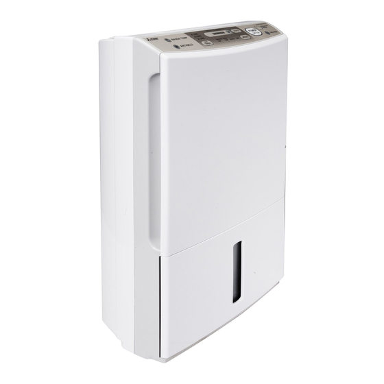
DEHUMIDIFIER
SERVICE MANUAL
Model
CONTENTS
1. PRODUCT SPECIFICATIONS........................................................................................ 2
2. OUTER DIMENSIONS .................................................................................................... 3
3. EXTERNAL VIEW, PARTS AND DISPLAY SECTION................................................... 3
4. NAMES AND FUNCTIONS OF PARTS....................................................................... 4 ~ 8
5. TECHNICAL POINTS................................................................................................... 9 ~ 11
6. MAINTENANCE ......................................................................................................... 12 ~ 13
7.1 Wiring Diagram....................................................................................................... 14
7.2 Function List ....................................................................................................... 14 ~ 16
7.3 Timing Charts ..................................................................................................... 17 ~ 19
7.4 General Block Diagram ...................................................................................... 20 ~ 21
8.1 Troubleshooting flowchart ................................................................................. 22 ~ 23
8.2 Key Component Check Procedures ....................................................................... 24
8.3 Error Indications and Corrective Actions ............................................................... 24
8.4 Self-Test Program and Execution Procedure ........................................................ 25
9. DISASSEMBLY AND REASSEMBLY HINTS .......................................................... 26 ~ 28
9.1 Disassembly Procedures ....................................................................................... 26
10. CONTINUOUS WATER DRAINAGE ............................................................................. 29
PARTS CATALOG .......................................................................................................... 30 ~ 37
11. TROUBLESHOOTING ............................................................................................... 38 ~ 39
PRECAUTIONS ............................................................................................................... 40 ~ 42
MJ-E16V-S1
ADVANCED AND EVER ADVANCING
MITSUBISHI ELECTRIC
Sold from 2005
2005
No.MJW-0502A
Advertisement
Table of Contents
Troubleshooting

Related Manuals for Mitsubishi MJ-E16V-S1


Summary of Contents for Mitsubishi MJ-E16V-S1
-
Page 1: Table Of Contents
ADVANCED AND EVER ADVANCING MITSUBISHI ELECTRIC 2005 DEHUMIDIFIER No.MJW-0502A SERVICE MANUAL MJ-E16V-S1 Model Sold from 2005 CONTENTS 1. PRODUCT SPECIFICATIONS..................2 2. OUTER DIMENSIONS ....................3 3. EXTERNAL VIEW, PARTS AND DISPLAY SECTION........... 3 4. NAMES AND FUNCTIONS OF PARTS............... 4 ~ 8 5. -
Page 2: Product Specifications
1. Product specifications Model MJ-E16V-S1 Item Dehumidifying capacity 16.0 (30°C room temperature, 80% relative humidity) (liters/day) Laundry Power supply (phases,V,Hz) Single phase, 220-240V, 50Hz Power consumption (W) Operating current (A) Starting current (A) Color tone Beige (C) 570 × 384 × 183 Dimensions (H ×... -
Page 3: Outer Dimensions
2. Outer Dimensions 3. External View, Parts and Display Section Drain the water tank before use Installing your dehumidifier Make sure to leave some space around the Refrain from opening unit. doors/windows during operation <For use in close proximity to At least 50 cm a wall>... -
Page 4: Names And Functions Of Parts
Do not block. Sensor Do not cover. Continuous drainage outlet Power plug NOTE It is impossible to remove the back panel because the two spots shown are fastened with two special screws. If the unit malfunctions, contact your Mitsubishi dealer:... - Page 5 Control Panel ¡OFF Timer ¡Lamp ¡Power ¡ Drying inside lamp Lamp button Current mode lights. ¡Auto button Flashes when Set time lights. Use this to ¡OFF Timer drying inside in Switches mode to switch the unit progress. button AUTO. ON and OFF. ¡Mode button ¡...
- Page 6 Modes AUTO LOW, LAUNDRY, LOW TEMP and AIR PURIFIER When you want to dehumidify easily. LOW mode is for when you want to leave the dehumidifier on, LAUNDRY mode is for when you want to dry laundry, LOW TEMP mode is for preventing condensation or when the room temperature is low and AIR PURIFIER mode is for when you want to use only the...
- Page 7 ¡ Drying inside The inside of the unit can be dried to suppress mildew growth on the cooler. On days the dehumidifier is used, drying inside is recommended. Automatic operation Manual operation To activate drying inside after every use. To activate drying inside by pressing a button. Press Press while the unit is off...
- Page 8 [OFF Timer Operation] [Removing Water from the Tank] The OFF timer can be set for each 2, 4, 8 hours. The unit automatically shuts down and lights the Tank Set the timer when the power is switched on. full lamp when the tank (approximately 4L) is full. Empty the tank.
-
Page 9: Technical Points
5. Technical points 5.1 The technical points of the new products 1) Drying inside During dehumidification, moisture accumulates on the heat exchanger. If left, this can lead to mildew growth, which is circulated around the room with the air discharge. Drying inside starts automatically after operation, and dries any moisture inside the unit. - Page 10 5.2 Operation and Performance Working temperature Defrosting Dehumidification is possible with a room The unit may display during operation and stop air temperature of 1 – 35°C. If the room temperature flow, followed by a change in the operating noise. The exceeds 35°C, however, the temperature inside the unit has stopped the airflow, and is melting internal frost unit will increase;...
- Page 11 5.3 Coolant Circuit φ6.35 Compressor Coolant flow Dehumidifying φ5 Defrosting φ5 φ6.35 Tube temperature φ6.35 sensing thermistor Solenoid valve Intake Blow (closed when dehumidifying and open when defrosting) Capillary tube Humidity sensor φ5.0 × φ4.0 Room temperature sensing thermistor φ6.35 φ6.35 Capillary tube φ2.0 ×...
-
Page 12: Maintenance
6. Maintenance Maintenance Do not use detergents, cleaning agents for heat exchange equipment, abrasive powders, chemically treated dusters, gasoline, benzene, thinners or other solvents, as they can damage the unit or the water tank, which may result in leakage. Cleaning Water tank ·... - Page 13 Store the unit. ∞ Type code: 5C5 813 ¡ When you are sure that all parts of the For these items contact your nearest Mitsubishi unit are dry, cover it with a cloth to keep Electric dealer. it from dust.
-
Page 14: Wiring Diagram And Block Diagram
7. Wiring Diagram and Block Diagram 7.1 Wiring Diagram Control board Sensors (Humidity and room P200 temperature sensing) P100 Gray Run capacitor 1°C (defrost)/12°C (end) Gray Thermistor (Tube White temperature sensing) Blue Power supply board White Brown Power plug Gray Tank full switch Gray Safety Devices... - Page 15 <Operation Control> 1 Specifications shared at all operation modes The compressor and blower fan will operate for about 6 minutes after turning on the operation switch or activating the compressor, regardless of humidity or temperature levels. 2 Low, Low Temp, Air Purifier Fan temperature table Compressor 16°C...
- Page 16 4 Drying inside 1. Controls (a) Prevents the growth of mildew by drying the moisture accumulated on the heat exchanger when the dehumidifier is OFF. (b) Drying inside operation does not depend on having a full water level. (c) The following operations are performed during drying inside operation. Target part Compressor Airflow fan Solenoid valve...
-
Page 17: Timing Charts
7.3. Timing Charts When room temperature is Easy dehumidifying/ Mode Low temp Tank full/ Power OFF between 20 and 27 Decrease in room Power Power Mode button AUTO Increase in room Tank full Drain temperature temperature Operation switch Easy Easy Low temp Operation mode dehumidifying... - Page 18 Defrost Off timer Defrost count Defrost Defrost Off timer Off timer Off timer After 2 hr. After 4 hr. After 1 hr. start start finish Operation switch 4 hr. 2 hr. 2 hr. Mode lamp Timer lamp Timer button Compressor Solenoid valve Blower fan Tube...
- Page 19 Cleaning inside (manual) Cleaning inside (automatic) Tube temperature Cleaning Tube temperature Cleaning Cleaning inside switch Cleaning inside switch Operation OFF inside complete inside complete Start Cleaning inside Operation switch Operation mode lamp Cleaning inside switch Cleaning inside lamp 30 min. 30 min.
-
Page 20: General Block Diagram
7.4 General Block Diagram... -
Page 22: Troubleshooting Procedure
8. Troubleshooting Procedure 8.1 Troubleshooting flowchart The unit does not operate Start Abnormal Restore AC power supply Check AC power supply Normal Blown Has the fuse blown out? Replace fuse Not blown Is the float switch turned on? Mechanical check •... - Page 23 Step 3 Does the compressor operate? (NO if stalled) Is there an overcurrent? Replace compressor *The compressor does not operate for (Surface is hot) 3 minutes after turning the power ON or OFF. (See page 10) Check connectors Is the compressor relay Check board operating properly? (open/bridge)
-
Page 24: Key Component Check Procedures
8.2 Key Component Check Procedures Component name Testing procedure Detach the connector and measure the resistance using a multimeter (component temperature: 10°C to 30°C). Tub temperature sensing thermistor Normal Abnormal Open or shorted Between P11 pins: 8.0kΩ to 20.8kΩ Detach the connector and measure the resistance using a multimeter Room (component temperature: 10°C to 30°C). -
Page 25: Self-Test Program And Execution Procedure
8.4 Self-Test Program and Execution Procedure (1) Deactivating 3-minute restart prevent lock ●Start: Press the MODE and AUTO buttons together 3 times when the power is off. Press the POWER button within 2 seconds. ●Functions: 1 Deactivates 3-minute restart prevention lock (immediate operation) 2 Fan: Fix at rank 6 (max. -
Page 26: Disassembly And Reassembly Hints
9. Disassembly and Reassembly Hints 9.1 Disassembly Procedures Picture 1 1. Remove the water tank (Pic. 1.) 2. Removing the front panel, and air filter Catch assembly Step 1) Push the front panel downward, and pull toward you (to release the catch on the bottom). - Page 27 [To remove the control board] Picture 6 Step 1) Pull the front casing/switch operation part toward the outside, release the catch (protrusion) on the switch button on the main board cover side, and remove the main board cover assembly. (Pic. 6) Step 2) Release the main board catches (4 below, 1 on the right), and remove the main board.
- Page 28 5. To remove the fan assembly Picture 13 Step 1) Remove the water tank, front panel, air filter assembly, front casing assembly, main board, and rear casing following the steps for sections 1 to 4 above. Valve Step 2) Remove the condenser and connectors (9) from the power board.
-
Page 29: Continuous Water Drainage
10. Continuous Water Drainage If a drain is available, the unit can continuously drain excess water by attaching a commercially available hose (internal diameter 15mm). The unit can be operated for extensive periods without the need to empty the water tank. ¡Commercially available hose (ID 15mm) CAUTION Long enough to reach the drain. -
Page 30: Parts Catalog
Parts Catalog Model MJ-E16V-S1 Exploded View <Casing and Structure> magnifing picture... - Page 31 Parts Catalog Model MJ-E16V-S1 Parts List <Casing and Structure> Notes: 1. Circled reference numbers indicate performance parts. 2. New parts and the parts that are used only with these models lack compatibility. 3. Those parts that are marked by are of critical importance for sustaining safety and performance. Use specified parts atreplacement.
- Page 32 Parts Catalog Model MJ-E16V-S1 Exploded View <Casing and Structure>...
- Page 33 Parts Catalog Model MJ-E16V-S1 Parts List <Casing and Structure> Notes: 1. Circled reference numbers indicate performance parts. 2. New parts and the parts that are used only with these models lack compatibility. 3. Those parts that are marked by are of critical importance for sustaining safety and performance. Use specified parts atreplacement.
- Page 34 Parts Catalog Model MJ-E16V-S1 Exploded View <Electrical Parts>...
- Page 35 Parts Catalog Model MJ-E16V-S1 Parts List <Electrical Parts> Notes: 1. Circled reference numbers indicate performance parts. 2. New parts and the parts that are used only with these models lack compatibility. 3. Those parts that are marked by are of critical importance for sustaining safety and performance. Use specified parts atreplacement.
- Page 36 Parts Catalog Model MJ-E16V-S1 Exploded View <Compressor Parts> 12 18 back...
- Page 37 Parts Catalog Model MJ-E16V-S1 Parts List <Compressor Parts> Notes: 1. Circled reference numbers indicate performance parts. 2. New parts and the parts that are used only with these models lack compatibility. 3. Those parts that are marked by are of critical importance for sustaining safety and performance. Use specified parts atreplacement.
-
Page 38: Troubleshooting
11. Troubleshooting ¡ For the symptoms listed below, refer to the remedies listed right. Symptom Cause/Remedy ¡ Dehumidified air passes through heating coils causing it to The unit blows warm air warm (this unit is not a cooler). This is not a malfunction. ¡... - Page 39 Symptom Cause/Remedy ¡ Check to see if the unit is on a slope or uneven surface. ➝ Move to a sturdy even surface. The operating ¡ Check to see if the pre-filter is clogged. noise is → Clean according to the maintenance procedures. loud/reverberates ¡...
-
Page 40: Precautions
Precautions The following diagrams indicate circumstances where Meanings of the graphic symbols used in this manual and danger can result from mishandling the unit. on the unit are explained below. Always Do not Forbidden follow the WARNING CAUTION disassemble instructions Mishandling may result Mishandling may result in Keep... - Page 41 CAUTION Do not cover the front or side air Do not drain water continuously if intakes or the air outlet with cloth, there is a possibility that curtain, etc. temperature around the hose could drop to freezing point. Water inside the hose may freeze and prevent This results in poor ventilation and the water in the tank from flowing out.
- Page 42 Precautions (cont.) Warning CAUTION ● Keep the unit always in an upright position. Inclining the unit may cause water in the tank to leak into the unit, resulting in malfunction. After emptying the tank, Should this happen contact service number on transport the unit by grasping the last page for advice.
- Page 43 Packaging diagram...
- Page 44 Issued in 2005.07 Printed in Japan...