Table of Contents
Advertisement
Quick Links
Advertisement
Table of Contents

Related Manuals for IBASE Technology SI-62 Series


Summary of Contents for IBASE Technology SI-62 Series
- Page 1 SI-62 Series User Manual 2014 Jan V1 IBASE Technology Inc.
- Page 3 SI-62 User Manual Copyright © 2013 IBASE Technology Inc. All Rights Reserved. No part of this manual, including the products and software described in it, may be reproduced, transmitted, transcribed, stored in a retrieval system, or translated into any language in any form or by any means, except documentation kept by the purchaser for backup purposes, without the express written permission of IBASE Technology INC.
-
Page 4: Table Of Contents
SI-62 User Manual Table of Contents Setting up your system ....................3 Care during use ......................4 Acknowledgments......................5 CHAPTER 1 INTRODUCTION ..................6 1.1 General Description ....................6 1.2 System Specifications ....................7 1.2.1 Hardware Specifications ..................7 1.2.2 Dimensions......................8 1.2.3 I/O View ........................ -
Page 5: Setting Up Your System
SI-62 User Manual Safety Information Your SI-62 is designed and tested to meet the latest standards of safety for information technology equipment. However, to ensure your safety, it is important that you read the following safety instructions Setting up your system ... -
Page 6: Care During Use
SI-62 User Manual Care during use Do not walk on the power cord or allow anything to rest on it. Do not spill water or any other liquids on your system. When the system is turned off, a small amount of electrical current still flows. Always unplug all power, and network cables from the power outlets before cleaning the system. -
Page 7: Acknowledgments
FINTEK is a registered trademark of FINTEK Electronics Corporation. REALTEK is a registered trademark of REALTEK Electronics Corporation. All other product names or trademarks are properties of their respective owners. Copyright © 2013 IBASE Technology Inc. All Rights Reserved. -
Page 8: Chapter 1 Introduction
SI-62 User Manual CHAPTER 1 INTRODUCTION 1.1 General Description SI-62 digital signage player comes with 2nd/3rd Gen. Intel Core i7/i5/i3 Celeron Quad Core/Dual Core processors and Intel HD Integrated Graphics Engine. It supports DVI-I and HDMI output, 2 x USB 3.0, 1x RJ45 for RS-232, 1x Gigabit LAN giving a great selection for data communication in display applications. -
Page 9: System Specifications
-20° ~ 80°C (-4°F~176°F) Relative Humidity 5~90% @45°C (non-condensing) Vibration mSATA: 5 Grms/5~500Hz random operation RoHS Certification CE, FCC class B, CCC and UL ‧ This specification is subject to change without prior notice. Copyright © 2013 IBASE Technology Inc. All Rights Reserved. -
Page 10: Dimensions
SI-62 User Manual 1.2.2 Dimensions... -
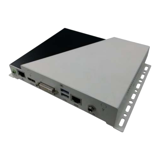
Page 11: I/O View
IBASE Technology Inc. 1.2.3 I/O View Item Connector Item Connector Line-out 2 x USB 3.0 Gigabit LAN RJ45 for RS-232 HDMI 12V DC in Copyright © 2013 IBASE Technology Inc. All Rights Reserved. -
Page 12: Exploded View Of The Si-62 Assembly
SI-62 User Manual 1.3 Exploded View of the SI-62 Assembly 1.3.1 Parts Description Part No. Description Part No. Description SI-62 side bracket Base 2.5” HDD bracket Top cover 2.5” HDD Thermal pad Heatsink Gasket Memory DIP PCBA LAN gasket... -
Page 13: Packing List
Cable; EXT-311 2-HD 10C, 150CM; DSUB-9F => EXT-311 RJ45-10M RoHS (C501EXT3110A12000P) Cable; EXT-312 2-HD 10C, 150CM; DSUB-9M => EXT-312 RJ45-10M RoHS (C501EXT3120A12000P) Description Display Cable DVI-22 3-HD, 10CM; DVI => DVI, VGA-15 RoHS DVI-22 (C501DVI2200103000P) Copyright © 2013 IBASE Technology Inc. All Rights Reserved. -
Page 14: Hardware Installation
SI-62 User Manual 2 HARDWARE INSTALLATION 2.1 Installing the CPU The IB902A board supports rPGA988B socket for Intel® Ivy Bridge Dual Core mobile processors. The processor socket comes with a screw to secure the processor. As shown in the picture below, loosen the screw first before inserting the processor. Place the processor into the socket by making sure the notch on the corner of the CPU corresponds with the notch on the inside of the socket. -
Page 15: Installing The Memory
2. Gently push the DDR3 module in an upright position until the clips of the slot close to hold the DDR3 module in place when the DDR3 module touches the bottom of the slot. 3. To remove the DDR3 module, press the clips with both hands. Copyright © 2013 IBASE Technology Inc. All Rights Reserved. -
Page 16: Installing The Hdd Module
SI-62 User Manual 2.3 Installing the HDD Module HDD Module: 1. Remove the four screws on the sides that are used to secure the top cover to the chassis. Once all the screws are removed, from the side, push the cover forward to remove it. - Page 17 2. Loosen the mounting screws that secure the HDD to the bracket. 3. As in the following the picture’s arrowed direction, push out the HDD module. 4. Loosen the four screws and then replace the HDD module. Copyright © 2013 IBASE Technology Inc. All Rights Reserved.
-
Page 18: Chapter 3 Motherboard Introduction
SI-62 User Manual CHAPTER 3 MOTHERBOARD INTRODUCTION 3.1 Introduction The IB902A motherboard is based on the latest Intel® QM77 chipset. The platform supports 3rd generation Intel® Core processor family with rPGA988B packing and features an integrated dual-channel DDR3 memory controller as well as a graphics core. - Page 19 Power Supply Power Power Jack (+12V DC) Environmental Temperature Operating: 0°C~ 40°C (32°F~104°F) Storage: -20oC to 80oC(-4oF~167oF) Humidity 10%~90% (non-condensing) Shock IBASE Standard Test Vibration IBASE Standard Test Certification RoHS Other CE/FCC Copyright © 2013 IBASE Technology Inc. All Rights Reserved.
- Page 20 SI-62 User Manual Board Dimensions...
-
Page 21: Setting The Jumpers
Jumpers are used on IB902A to select various settings and features according to your needs and applications. Contact your supplier if you have doubts about the best configuration for your needs. Jumper Locations on IB902A Copyright © 2013 IBASE Technology Inc. All Rights Reserved. - Page 22 SI-62 User Manual JP1: COM1 RS232 RI/+5V/+12V Power Setting Setting Function Pin 1-3 +12V Short/Closed Pin 3-4 Short/Closed Pin 3-5 Short/Closed J4: Clear CMOS Contents Setting Function Pin 1-2 Normal Short/Closed Pin 2-3 Clear CMOS Short/Closed...
- Page 23 IBASE Technology Inc. J7: Flash Descriptor Security Override (Factory use only) Flash Descriptor Security Override Open Disabled (Default) Close Enabled J10: Reset BTN Reset BTN Open Disabled (Default) Close Enabled Copyright © 2013 IBASE Technology Inc. All Rights Reserved.
-
Page 24: Connector Locations On Ib902A
SI-62 User Manual 3.3 Connector Locations on IB902A... - Page 25 DSR, Data set ready GND, ground GND, ground TXD, Transmit data RXD, Receive data DCD, Data carrier detect DTR, Data terminal ready CTS, Clear to send RTS, Request to send RI, Ring indicator Copyright © 2013 IBASE Technology Inc. All Rights Reserved.
- Page 26 SI-62 User Manual CN5: USB3 Connector CN6: Gigabit LAN (82579V) J1: +12V Power Supply Connector J5: Battery 1/2AA Connector Pin # Signal Name Ground...
- Page 27 J13: Digital I/O Connector (4 in, 4 out) Signal Name Pin # Pin # Signal Name Ground Out3 Out1 Out2 Out0 J14: DDR3 SO-DIMM Channel A J15: DDR3 SO-DIMM Channel B J16: Mini-PCIE Connector and mSATA Copyright © 2013 IBASE Technology Inc. All Rights Reserved.
- Page 28 SI-62 User Manual CPU_FAN1: CPU Fan Power Connector Signal Name Pin # Ground +12V Rotation detection SYS_FAN2: System Fan Power Connector Signal Name Pin # Ground +12V Rotation detection JP3: SPI Flash connector (Factory use only) JP4: LPC debug Connector (Factory use only)
-
Page 29: Chapter 4 Bios Setup
AMI and your system manufacturer to provide the absolute maximum performance and reliability. Changing the defaults could cause the system to become unstable and crash in some cases. Copyright © 2013 IBASE Technology Inc. All Rights Reserved. - Page 30 SI-62 User Manual Main Settings Aptio Setup Utility – Copyright © 2011 American Megatrends, Inc. Main Advanced Chipset Boot Security Save & Exit BIOS Information Choose the system default language Total memory 8176 MB (DDR3) Memory Frequency 1333Mhz → ← Select Screen System Date [Tue 01/20/2013]...
- Page 31 +- Change Field ► F81866 Super IO Configuration F1: General Help ► F81866 H/W Monitor F2: Previous Values F3: Optimized Default ► CPU PPM Configuration F4: Save ESC: Exit ►Sandybridge DTS Configuration Copyright © 2013 IBASE Technology Inc. All Rights Reserved.
- Page 32 SI-62 User Manual PCI Subsystem Settings Aptio Setup Utility Main Advanced Chipset Boot Security Save & Exit PCI Bus Driver Version V 2.0502 PCI 64bit Resources Handing Above 4G Decoding Disabled PCI Common Settings → ← Select Screen ↑↓ Select Item PCI Latency Timer 32 PCI Bus Clocks Enter: Select...
- Page 33 Set the ASPM Level: Force L0s – Force all links to L0s State: AUTO – BIOS auto configure: DISABLE – Disables ASPM. Extended Synch If ENABLED allows generation of Extended Synchronization patterns. Copyright © 2013 IBASE Technology Inc. All Rights Reserved.
- Page 34 SI-62 User Manual Link Training Retry Defines number of Retry Attempts software will take to retrain the link if previous training attempt was unsuccessful. Link Training Timeout (uS) Defines number of Microseconds software will wait before polling ‘Link Training’ bit in Link Status register.
- Page 35 Disabled Enter: Select +- Change Field F1: General Help F2: Previous Values F3: Optimized Default F4: Save ESC: Exit Wake on PCIE PME Wake Event The options are Disabled and Enabled. Copyright © 2013 IBASE Technology Inc. All Rights Reserved.
- Page 36 SI-62 User Manual CPU Configuration Aptio Setup Utility Main Advanced Chipset Boot Security Save & Exit CPU Configuration Intel® Core ™ i5-3610ME CPU @ 2.70GHz Processor Stepping 306a9 Microcode Revision Max CPU Speed 2700 MHz Min CPU Speed 1200 MHz CPU Speed 2700 MHz Processor Cores...
- Page 37 F1: General Help F2: Previous Values F3: Optimized Default Software Preserve Unknown F4: Save ESC: Exit SATA Controller(s) Enable / Disable Serial ATA Controller. SATA Mode Selection (1) IDE Mode. (2) AHCI Mode. Copyright © 2013 IBASE Technology Inc. All Rights Reserved.
- Page 38 SI-62 User Manual Shutdown Temperature Configuration Aptio Setup Utility Main Advanced Chipset Boot Security Save & Exit APCI Shutdown Temperature Disabled → ← Select Screen ↑↓ Select Item Enter: Select +- Change Field F1: General Help F2: Previous Values F3: Optimized Default F4: Save ESC: Exit ACPI Shutdown Temperature The default setting is Disabled.
- Page 39 Trigger CIRA boot. PET Progress User can Enable/Disable PET Events progress to receive PET events or not. Watchdog Timer This configuration is supported only with IB902AVF (with iAMT function). Enable/Disable Watchdog Timer. Copyright © 2013 IBASE Technology Inc. All Rights Reserved.
- Page 40 SI-62 User Manual USB Configuration Main Advanced Chipset Boot Security Save & Exit USB Configuration USB Devices: 2 Hubs Legacy USB Support Enabled USB3.0 Support Enabled XHCI Hand-off Enabled → ← Select Screen ↑↓ Select Item EHCI Hand-off Enabled Enter: Select +- Change Field F1: General Help USB hardware delays and time-outs:...
- Page 41 F3: Optimized Default F4: Save ESC: Exit Serial Port Configuration Set Parameters of Serial Ports. User can Enable/Disable the serial port and Select an optimal settings for the Super IO Device. Copyright © 2013 IBASE Technology Inc. All Rights Reserved.
- Page 42 SI-62 User Manual F81866 H/W Monitor Aptio Setup Utility Main Advanced Chipset Boot Security Save & Exit PC Health Status CPU temperature +32 C SYS temperature +35 C FAN1 Speed 5154 RPM FAN2 Speed Vcore +0.904 V Vcc5V +5.003 V Vcc12V +12.408 V →...
- Page 43 Enabled: ACPI thermal management uses DTS SMM mechanism to obtain CPU temperature values. Out of Spec: ACPI Thermal Management uses EC reported temperature values and TS SMM is used to handle Out of Spec. Copyright © 2013 IBASE Technology Inc. All Rights Reserved.
- Page 44 SI-62 User Manual Chipset Settings This section allows you to configure and improve your system and allows you to set up some system features according to your preference. Aptio Setup Utility Main Advanced Chipset Boot Security Save & Exit ► PCH-IO Configuration ►...
- Page 45 The control of Active State Power Management on both NB side and SB side of the DMI link. PCIe-USB Glitch W/A PCIe-USB Glitch W/A for bad USB device(s) connected behind PCIE/PEG port. Copyright © 2013 IBASE Technology Inc. All Rights Reserved.
- Page 46 SI-62 User Manual USB Configuration Main Advanced Chipset Boot Security Save & Exit USB Configuration XHCI Pre-Boot Driver Disabled xHCI Mode Auto HS Port #1 Switchable Enabled HS Port #2 Switchable Enabled HS Port #3 Switchable Enabled HS Port #4 Switchable Enabled xHCI Streams Enabled...
- Page 47 F4: Save ESC: Exit VT-d Check to enable VT-d function on MCH. Enable NB CRID Enable or disable NB CRID WorkAround. C-State Pre-Wake Controls C-State Pre-Wake feature for ARAT, in SSKPD[57]. Copyright © 2013 IBASE Technology Inc. All Rights Reserved.
- Page 48 SI-62 User Manual Graphics Configuration Aptio Setup Utility Main Advanced Chipset Boot Security Save & Exit Graphics Configuration IGFX VBIOS Version 2132 IGfx Frequency 350 MHz Primary Display Auto Internal Graphics Auto → ← Select Screen GTT Size ↑↓ Select Item Enter: Select Aperture Size 256MB...
- Page 49 ↑↓ Select Item Enter: Select CAS to RAS (tRCDmin) +- Change Field F1: General Help Row Precharge (tRPmin) F2: Previous Values F3: Optimized Default Active to Precharge (tRASmin) F4: Save ESC: Exit Copyright © 2013 IBASE Technology Inc. All Rights Reserved.
- Page 50 SI-62 User Manual Boot Settings Aptio Setup Utility Main Advanced Chipset Boot Security Save & Exit Boot Configuration Setup Prompt Timeout Bootup NumLock State Quiet Boot Disabled Fast Boot Disabled CSM16 Module Version 07.68 → ← Select Screen ↑↓ Select Item GateA20 Active Upon Request Enter: Select...
- Page 51 Launch Video OpROM policy Controls the execution of UEFI and Legacy Video OpROM. Other PCI device ROM priority For PCI devices other than Network, Mass storage or Video defines which OpROM to launch. Copyright © 2013 IBASE Technology Inc. All Rights Reserved.
- Page 52 SI-62 User Manual Security Settings This section allows you to configure and improve your system and allows you to set up some system features according to your preference. Aptio Setup Utility Main Advanced Chipset Boot Security Save & Exit Password Description If ONLY the Administrator’s password is set, then this only limit access to Setup and is only asked for when entering Setup.
- Page 53 Restore/Load Defaults values for all the setup options. Save as User Defaults Save the changes done so far as User Defaults. Restore User Defaults Restore the User Defaults to all the setup options. Copyright © 2013 IBASE Technology Inc. All Rights Reserved.
-
Page 54: Chapter 5 Drivers Installation
SI-62 User Manual CHAPTER 5 DRIVERS INSTALLATION This section describes the installation procedures for software and drivers. The software and drivers are included with the motherboard. If you find the items missing, please contact the vendor where you made the purchase. IMPORTANT NOTE: After installing your Windows operating system, you must install first the Intel Chipset Software Installation Utility before proceeding with the drivers installation. - Page 55 3. When the Welcome screen to the Intel® Chipset Device Software appears, click Next to continue. 4. Click Yes to accept the software license agreement and proceed with the installation process. Copyright © 2013 IBASE Technology Inc. All Rights Reserved.
- Page 56 SI-62 User Manual 5. On the Readme File Information screen, click Next to continue the installation. 6. The Setup process is now complete. Click Finish to restart the computer and for changes to take effect.
-
Page 57: Vga Drivers Installation
To install the VGA drivers, follow the steps below. 1. Insert the CD that comes with the board. Click Intel and then Intel(R) Q7 Series Chipset Drivers. 2. Click Intel(R) Q77 Chipset Family Graphics Driver. Copyright © 2013 IBASE Technology Inc. All Rights Reserved. - Page 58 SI-62 User Manual 3. When the Welcome screen appears, click Next to continue. 4. Click Yes to to agree with the license agreement and continue the installation.
- Page 59 5. On the Readme File Information screen, click Next to continue the installation of the Intel® Graphics Media Accelerator Driver. 6. On Setup Progress screen, click Next to continue. 7. Setup complete. Click Finish to restart the computer and for changes to take effect. Copyright © 2013 IBASE Technology Inc. All Rights Reserved.
-
Page 60: Realtek Hd Audio Driver Installation
SI-62 User Manual 5.3 Realtek HD Audio Driver Installation Follow the steps below to install the Realtek HD Audio Drivers. 1. Insert the CD that comes with the board. Click Intel and then Intel(R) Q7 Series Chipset Drivers. 2. Click Realtek High Definition Audio Driver. - Page 61 3. On the Welcome to the InstallShield Wizard screen, click Next to proceed with and complete the installation process. 4. The InstallShield Wizard Complete. Click Finish to restart the computer and for changes to take effect. Copyright © 2013 IBASE Technology Inc. All Rights Reserved.
-
Page 62: Lan Drivers Installation
SI-62 User Manual 5.4 LAN Drivers Installation 1. Insert the CD that comes with the board. Click Intel and then Intel(R) Q7 Series Chipset Drivers. 2. Click Intel(R) PRO LAN Network Driver. - Page 63 IBASE Technology Inc. 3. Click Install Drivers and Software. 4. When the Welcome screen appears, click Next. Copyright © 2013 IBASE Technology Inc. All Rights Reserved.
- Page 64 SI-62 User Manual 5. Click Next to to agree with the license agreement. 6. Click the checkbox for Drivers in the Setup Options screen to select it and click Next to continue.
- Page 65 IBASE Technology Inc. 7. The wizard is ready to begin installation. Click Install to begin the installation. 8. When InstallShield Wizard is complete, click Finish. Copyright © 2013 IBASE Technology Inc. All Rights Reserved.
-
Page 66: Intel® Management Engine Interface
SI-62 User Manual 5.5 Intel® Management Engine Interface Follow the steps below to install the Intel Management Engine. 1. Insert the CD that comes with the board. Click Intel and then Intel(R) AMT 8.0 Drivers. - Page 67 2. When the Welcome screen to the InstallShield Wizard for Intel® Management Engine Components, click the checkbox for Install Intel® Control Center & click Next. 3. Click Yes to to agree with the license agreement. Copyright © 2013 IBASE Technology Inc. All Rights Reserved.
- Page 68 SI-62 User Manual 4. When the Setup Progress screen appears, click Next. Then, click Finish when the setup progress has been successfully installed.
-
Page 69: Intel® Usb 3.0 Drivers
IBASE Technology Inc. 5.6 Intel® USB 3.0 Drivers 1. Insert the CD that comes with the board. Click Intel and then Intel(R) Q7 Series Chipset Drivers. 2. Click Intel(R) USB 3.0 Drivers. Copyright © 2013 IBASE Technology Inc. All Rights Reserved. - Page 70 SI-62 User Manual 3. When the Welcome screen to the InstallShield Wizard for Intel® USB 3.0 eXtensible Host Controller Driver, click Next. 4. Click Yes to to agree with the license agreement and continue the installation. 5. On the Readme File Information screen, click Next to continue the installation of the Intel®...
-
Page 71: Appendix
Choose fasteners that are rated either ”Medium Duty“ or ”Heavy Duty.“ To assure proper fastener selection and installation, follow the fastener manufacturer’s recommendations. Copyright © 2013 IBASE Technology Inc. All Rights Reserved. -
Page 72: Wall Mounting Requirements
SI-62 User Manual Wall Mounting Requirements Note: Before mounting the system on wall, ensure that you are following all applicable building and electric codes. When mounting, ensure that you have enough room for power and signal cable routing. And have good ventilation for power adapter. The method of mounting must be able to support weight of the SI-62 plus the suspend weight of all the cables to be attached to the system.