
Related Manuals for IBASE Technology SI-614


Summary of Contents for IBASE Technology SI-614
- Page 1 SI-614 / SI-614-M Extreme Performance Digital Signage Player User’s Manual Version 1.0 (Nov. 2018)
- Page 2 No part of this publication may be reproduced, copied, stored in a retrieval system, translated into any language or transmitted in any form or by any means, electronic, mechanical, photocopying, or otherwise, without the prior written consent of IBASE Technology, Inc. (hereinafter referred to as “IBASE”).
-
Page 3: Compliance
0.1% by weight (1000 ppm) except for cadmium, limited to 0.01% by weight (100 ppm). • Lead (Pb) • Mercury (Hg) • Cadmium (Cd) • Hexavalent chromium (Cr6+) • Polybrominated biphenyls (PBB) • Polybrominated diphenyl ether (PBDE) SI-614 / SI-614-M User Manual... -
Page 4: Important Safety Information
Avoid Disassembly Do not disassemble, repair or make any modification to the device. Doing so could generate hazards and cause damage to the device, even bodily injury or property damage, and will void any warranty. SI-614 / SI-614-M User Manual... -
Page 5: Caution
Software in use (such as OS and application software, including the version numbers) 3. If repair service is required, you can download the RMA form at http://www.ibase.com.tw/english/Supports/RMAService/. Fill out the form and contact your distributor or sales representative. SI-614 / SI-614-M User Manual... -
Page 6: Table Of Contents
Jumper & Connector Locations on Motherboard ........16 Jumpers Quick Reference ..............17 2.7.1 Clearing CMOS Data (JBAT2) ..........17 2.7.2 Clearing ME Register (JBAT1) ..........17 Connectors Quick Reference ..............18 2.8.1 Front Panel Setting Connector (J1) ........19 SI-614 / SI-614-M User Manual... - Page 7 4.4.9 CSM Configuration ..............38 4.4.10 NVMe Configuration ............... 38 4.4.11 USB Configuration ..............39 Appendix ...................... 40 I/O Port Address Map ................41 Interrupt Request Lines (IRQ) ............... 43 Watchdog Timer Configuration .............. 44 SI-614 / SI-614-M User Manual...
-
Page 8: Chapter 1 General Information
Chapter 1 General Information The information provided in this chapter includes: • Features • Packing List • Accessories • Specifications • Overview • Dimensions... -
Page 9: Introduction
3X the performance of previous-generation graphics cards. The SI-614 digital signage player is designed for digital signage applications within hospitality, retail and education sectors to empower the establishments to connect and communicate with their guests, customers and audience, reliably delivering high-quality live video and digital signage content. -
Page 10: Packing List
Your product package should include the items listed below. If any of the items below is missing, contact the distributor or the dealer from whom you purchased the product. • SI-614 / SI-614-M Digital Signage Player • Power Adapter •... - Page 11 Note: The product performance relies on the system functioning as a whole. The level of CPU/APU/GPU processor, the interaction among the processor and the memory and storage bandwidth, or the functionality of the digital signage application software may affect the product performance. SI-614 / SI-614-M User Manual...
-
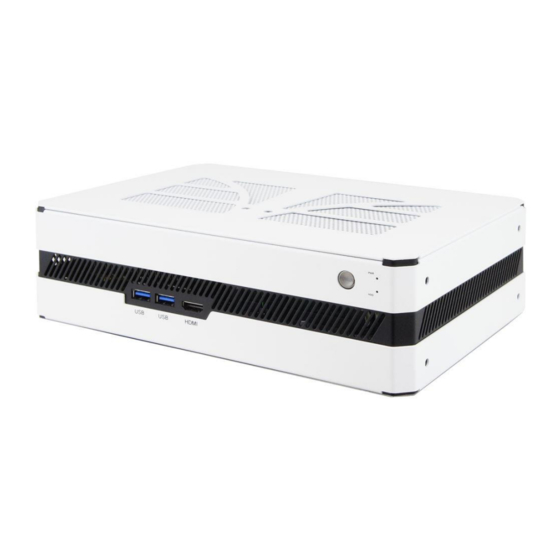
Page 12: Overview
Power Button Rear View No. Name Name DC Power Input Audio Line-Out LAN Port Antenna Hole DisplayPorts COM1 RS-232 Port (RJ50) USB 3.0 Ports Reserved HDMI 1.4 Port 2-Pin Terminal Block (for external power button) SI-614 / SI-614-M User Manual... - Page 13 Oblique View SI-614 / SI-614-M User Manual...
-
Page 14: Dimensions
General Information 1.6 Dimensions Unit: mm SI-614 / SI-614-M User Manual... -
Page 15: Hardware Installation & Motherboard Information
Chapter 2 Hardware Installation & Motherboard Information The information provided in this chapter includes: • Installation of memory, M.2 and mini PCIe card • Information and locations of connectors... -
Page 16: Installation / Replacement
3. Gently push the module in an upright position unitl the ejector tabs of the memory slot close to hold the module in place when the module touches the bottom of the slot. To remove the module, press the ejector tabs outwards with your fintertips to eject the module. SI-614 / SI-614-M User Manual... -
Page 17: Ssd
1. Locate the mini-PCIe or M.2 slot inside the device. 2. Align the key of the mini-PCIe card to the mini-PCIe interface, and insert the card slantwise. (Insert the M.2 card in the same way.) SI-614 / SI-614-M User Manual... -
Page 18: Wifi / 3G / 4G Antenna Installation
1. Thread and fasten the hex nut and the 2. Apply adhesive around here. washer. Then install the antenna. Info: The diameter of the nut is around 6.35 mm (0.25”-36UNC). SI-614 / SI-614-M User Manual... -
Page 19: Mounting Installation
8 screws. 2. Prepare at least 4 screws (M3) to install the device on the wall as shown. You can also install the wall mount kit onto either side of the device. SI-614 / SI-614-M User Manual... -
Page 20: Pin Assignment For Dc Power Input Connector
Hardware Configuration 2.2 Pin Assignment for DC Power Input Connector ➔ Signal Name Signal Name +19V +19V Ground Ground 2.3 Pin Assignment for External Power Input Connector ➔ Signal Name Signal Name Ground PWR_SW SI-614 / SI-614-M User Manual... -
Page 21: Pin Assignment For Com1 Rs-232 Port
COM1 port is jumper-less and configurable in BIOS. Signal Name Signal Name DSR, Data set ready DCD, Data carrier detect Ground DTR, Data terminal ready Ground CTS, Clear to send TX, Transmit RTS, Request to send RX, Receive RI, Ring Indicator SI-614 / SI-614-M User Manual... -
Page 22: Setting The Jumpers
When two pins of a jumper are encased in a jumper cap, this jumper is closed, i.e. turned On. When a jumper cap is removed from two jumper pins, this jumper is open, i.e. turned Off. SI-614 / SI-614-M User Manual... -
Page 23: Jumper & Connector Locations On Motherboard
2.6 Jumper & Connector Locations on Motherboard Motherboard: MBD614 MBD614 – top and I/O MBD614 - bottom SI-614 / SI-614-M User Manual... -
Page 24: Jumpers Quick Reference
Page Clearing CMOS Data JBAT2 Clearing ME Register JBAT1 2.7.1 Clearing CMOS Data (JBAT2) Function Pin closed Illustration Normal (default) Clear CMOS 2.7.2 Clearing ME Register (JBAT1) Function Pin closed Illustration Normal (default) Clear ME SI-614 / SI-614-M User Manual... -
Page 25: Connectors Quick Reference
M.2 M2280 Slot with SATA & PCIe (x4) M.2 B3042 Slot with USB 2.0 Mini-PCIe Slot SIM Card Socket Factory Use Only J2, J8, J9 [1]: Refer to 2.2 Pin Assignment for DC Power Input Connector. SI-614 / SI-614-M User Manual... -
Page 26: Front Panel Setting Connector (J1)
Signal Name Signal Name Power BTN- Power BTN+ Powe LED+ Powe LED- HDD LED+ HDDLED- Reset BTN- Reset BTN+ 2.8.2 USB 2.0 Connector (J3, J5) Signal Name Signal Name Data- Data- Data+ Data+ Ground Ground SI-614 / SI-614-M User Manual... -
Page 27: Cpu Fan Power Connector (Cpu_Fan1, Cpu_Fan2)
2.8.3 CPU Fan Power Connector (CPU_FAN1, CPU_FAN2) CPU_FAN1 CPU_FAN2 Signal Name Signal Name Ground Rotation detection +12V Control 2.8.4 Ditigal I/O Connector (J7) Signal Name Signal Name Ground Out3 Out1 Out2 Out0 SI-614 / SI-614-M User Manual... -
Page 28: External Power Botton Connector (J10)
COM1 port is jumper-less and configurable in BIOS. Signal Name Signal Name DSR, Data set ready DCD, Data carrier detect Ground DTR, Data terminal ready Ground CTS, Clear to send TX, Transmit RTS, Request to send RX, Receive RI, Ring Indicator SI-614 / SI-614-M User Manual... -
Page 29: Sata Connector (J11, J12)
SATA Connector (J11, J12) Signal Name Signal Name Ground Ground Ground Ground Ground 2.8.8 MXM Connector (CN4) Signal Name Signal Name Signal Name Signal Name PWR_SRC PWR_SRC PEX_RX1# PEX_TX1# Ground Ground PEX_RX1 PEX_TX1 PRSNT_R# Ground Ground SI-614 / SI-614-M User Manual... - Page 30 PEX_TX14# Ground Ground PEX_RX14# PEX_TX14 DP_C_L0# DP_E_L2# PEX_RX14 Ground DP_C_L0 DP_E_L2 Ground PEX_TX13# Ground Ground PEX_RX13# PEX_TX13 DP_C_L1# DP_D_L0# PEX_RX13 Ground DP_C_L1 DP_D_L0 Ground PEX_TX12# Ground Ground PEX_RX12# PEX_TX12 DP_C_L2# DP_D_L1# PEX_RX12 Ground DP_C_L2 DP_D_L1 SI-614 / SI-614-M User Manual...
- Page 31 Ground DP_A_L1 Ground Ground PEX_TX3# Ground DP_B_L3# PEX_RX3# PEX_TX3 DP_A_L2# DP_B_L3 PEX_RX3 Ground DP_A_L2 Ground Ground Ground DP_B_AUX# DP_A_L3# DP_B_AUX DP_A_L3 DP_B_HPD Ground DP_A_HPD Ground Ground DP_A_AUX# PEX_RX2# PEX_TX2# DP_A_AUX PEX_RX2 PEX_TX2 PRSNT_L# Ground Ground SI-614 / SI-614-M User Manual...
-
Page 32: Chapter 3 Driver Installation
Chapter 3 Driver Installation The information provided in this chapter includes: • ® Intel Chipset Software Installation Utility • HD Audio Driver Installation • LAN Driver Installation • ® Intel Management Engine Component Drivers Installation... -
Page 33: Introduction
2. When the Welcome screen to the Intel Chipset Device Software appears, click Next to continue. 3. Accept the license agreement and proceed with the installation process. 4. When the driver is completely installed, restart the computer for changes to take effect. SI-614 / SI-614-M User Manual... -
Page 34: Hd Audio Driver Installation
3. Accept the license agreement and click Next to continue. 4. On the Setup Options screen, tick the checkbox to select the desired driver(s) and click Next for installation. When the driver is completely installed, restart the computer for changes to take effect. SI-614 / SI-614-M User Manual... -
Page 35: Intel Management Engine Components Drivers Installation
® ® 3.6 NVIDIA GeForce MXM Driver Installation 1. Download the driver from NVIDIA’s website or IBASE’s website. 2. Accept the software license agreement and start installation. 3. Click Close to finish the installation. SI-614 / SI-614-M User Manual... -
Page 36: Chapter 4 Bios Setup
Chapter 4 BIOS Setup This chapter describes the different settings available in the AMI BIOS that comes with the board. The topics covered in this chapter are as follows: • Main Settings • Advanced Settings • Chipset Settings • Security Settings •... -
Page 37: Introduction
These defaults have been carefully chosen by both AMI and your system manufacturer to provide the absolute maximum performance and reliability. Changing the defaults could make the system unstable and crash in some cases. SI-614 / SI-614-M User Manual... -
Page 38: Main Settings
Use the <Tab> key to switch between the data elements. 4.4 Advanced Settings This section allows you to configure, improve your system and allows you to set up some system features according to your preference. SI-614 / SI-614-M User Manual... -
Page 39: Cpu Configuration
Number of cores to enable in each processor package. Intel Trusted Execution Enables / Disables utilization of additional Technology hardware capabilities provided by Intel(R) Trusted Execution Technology. Changes require a full power cycle to take effect. SI-614 / SI-614-M User Manual... -
Page 40: Power & Performance
BIOS Setup 4.4.2 Power & Performance BIOS Setting Description CPU – Power CPU power management control options. Management Control 4.4.3 PCH-FW Configuration SI-614 / SI-614-M User Manual... -
Page 41: Acpi Settings
Enables / Disables system ability to hibernate (OS/S4 Sleep State). This option may not be effective with some operating systems. ACPI Sleep State Selects the highest ACPI sleep state the system will enter when the SUSPEND button is pressed. SI-614 / SI-614-M User Manual... -
Page 42: Ismart Controller
For example, if setting up a schedule from Wednesday 5 p.m. to Thursday 2 a.m., configure two schedule slots. But if setting up a schedule from 3 p.m to 5 p.m. on Wednesday, configure only a schedule slot. SI-614 / SI-614-M User Manual... -
Page 43: Nct5523D Super Io Configuration
4.4.6 NCT5523D Super IO Configuration BIOS Setting Description Serial Port 1 Configuration Sets parameters of Serial Port 1 (COMA). Enables / Disables the serial port and select an optimal setting for the Super IO device. SI-614 / SI-614-M User Manual... -
Page 44: Nct5523D Hardware Monitor
The values are read-only values as monitored by the system and show the PC health status. 4.4.8 Network Stack Configuration BIOS Setting Description Network Stack Enables / Disables UEFI Network Stack. SI-614 / SI-614-M User Manual... -
Page 45: Csm Configuration
4.4.9 CSM Configuration BIOS Setting Description Network Controls the execution of UEFI and Legacy PXE OpROM. 4.4.10 NVMe Configuration SI-614 / SI-614-M User Manual... -
Page 46: Usb Configuration
The maximum time the device will take before it properly reports itself to the Host Controller. “Auto” uses default value for a Root port it is 100ms. But for a Hub port, the delay is taken from Hub descriptor. SI-614 / SI-614-M User Manual... -
Page 47: Appendix
Appendix This section provides the mapping addresses of peripheral devices and the sample code of watchdog timer configuration. • I/O Port Address Map • Interrupt Request Lines (IRQ) • Watchdog Timer Configuration... -
Page 48: I/O Port Address Map
0x0000164E-0x0000164F Motherboard resources 0x00000800-0x0000087F Motherboard resources 0x000000F0-0x000000F0 Numeric data processor 0x0000F050-0x0000F057 Standard SATA AHCI Controller 0x0000F040-0x0000F043 Standard SATA AHCI Controller 0x0000F020-0x0000F03F Standard SATA AHCI Controller 0x000003F8-0x000003FF Communications Port (COM1) 0x00000040-0x00000043 System timer 0x00000050-0x00000053 System timer SI-614 / SI-614-M User Manual... - Page 49 0x000000A4-0x000000A5 Programmable interrupt controller 0x000000A8-0x000000A9 Programmable interrupt controller 0x000000AC-0x000000AD Programmable interrupt controller 0x000000B0-0x000000B1 Programmable interrupt controller 0x000000B4-0x000000B5 Programmable interrupt controller 0x000000B8-0x000000B9 Programmable interrupt controller 0x000000BC-0x000000BD Programmable interrupt controller 0x000004D0-0x000004D1 Programmable interrupt controller 0x00001854-0x00001857 Motherboard resources SI-614 / SI-614-M User Manual...
-
Page 50: Interrupt Request Lines (Irq)
Intel(R) 100 Series/C230 Series Chipset Family Thermal subsystem - A131 IRQ 4294967292 Intel(R) Ethernet Connection (2) I219-V IRQ 4294967290 NVIDIA GeForce GTX 1050 IRQ 8 System CMOS/real time clock IRQ 16 High Definition Audio Controller SI-614 / SI-614-M User Manual... -
Page 51: Watchdog Timer Configuration
NCT5523D_DATA_PORT (NCT5523D_BASE+1) //--------------------------------------------------------------------------- #define NCT5523D_REG_LD 0x07 //--------------------------------------------------------------------------- #define NCT5523D_UNLOCK 0x87 #define NCT5523D_LOCK 0xAA //--------------------------------------------------------------------------- unsigned int Init_NCT5523D(void); void Set_NCT5523D_LD( unsigned char); void Set_NCT5523D_Reg( unsigned char, unsigned char); unsigned char Get_NCT5523D_Reg( unsigned char); //--------------------------------------------------------------------------- #endif //__NCT5523D_H SI-614 / SI-614-M User Manual... - Page 52 Nuvoton NCT5523D, program abort.\n"); return(1); WDTInitial(); WDTEnable(10); WDTDisable(); return 0; //--------------------------------------------------------------------------- void WDTInitial(void) unsigned char bBuf; Set_NCT5523D_LD(0x08); //switch to logic device 8 bBuf = Get_NCT5523D_Reg(0x30); bBuf &= (~0x01); Set_NCT5523D_Reg(0x30, bBuf); //Enable WDTO //--------------------------------------------------------------------------- void WDTEnable(unsigned char NewInterval) SI-614 / SI-614-M User Manual...
- Page 53 = Get_NCT5523D_Reg(0xF0); bBuf &= (~0x08); Set_NCT5523D_Reg(0xF0, bBuf); //count mode is second Set_NCT5523D_Reg(0xF1, NewInterval); //set timer //--------------------------------------------------------------------------- void WDTDisable(void) Set_NCT5523D_LD(0x08); //switch to logic device 8 Set_NCT5523D_Reg(0xF1, 0x00); //clear watchdog timer Set_NCT5523D_Reg(0x30, 0x00); //watchdog disabled //--------------------------------------------------------------------------- SI-614 / SI-614-M User Manual...
- Page 54 = Get_NCT5523D_Reg(0x20); if (ucDid == 0xC4) //NCT5523D?? goto Init_Finish; } NCT5523D_BASE = 0x00; result = NCT5523D_BASE; Init_Finish: return (result); //--------------------------------------------------------------------------- void Unlock_NCT5523D (void) outportb(NCT5523D_INDEX_PORT, NCT5523D_UNLOCK); outportb(NCT5523D_INDEX_PORT, NCT5523D_UNLOCK); //--------------------------------------------------------------------------- void Lock_NCT5523D (void) outportb(NCT5523D_INDEX_PORT, NCT5523D_LOCK); //--------------------------------------------------------------------------- SI-614 / SI-614-M User Manual...
- Page 55 Lock_NCT5523D(); //--------------------------------------------------------------------------- void Set_NCT5523D_Reg( unsigned char REG, unsigned char DATA) Unlock_NCT5523D(); outportb(NCT5523D_INDEX_PORT, REG); outportb(NCT5523D_DATA_PORT, DATA); Lock_NCT5523D(); //--------------------------------------------------------------------------- unsigned char Get_NCT5523D_Reg(unsigned char REG) unsigned char Result; Unlock_NCT5523D(); outportb(NCT5523D_INDEX_PORT, REG); Result = inportb(NCT5523D_DATA_PORT); Lock_NCT5523D(); return Result; //----------------------------------------------------------------------- SI-614 / SI-614-M User Manual...