Hitachi EH-150 Applications Manual
Hidic cpu link module (eh-lnk)
Hide thumbs
Also See for EH-150:
- Engineering manualline (9 pages) ,
- Applications manual (176 pages) ,
- Applications manual (58 pages)

Related Manuals for Hitachi EH-150


Summary of Contents for Hitachi EH-150
- Page 1 HITACHI PROGRAMMABLE CONTROLLER CPU LINK MODULE (EH-LNK) APPLICATION MANUAL NJI-381(X)
- Page 2 If you have any questions regarding the warranty please contact either your supplier or the local Hitachi Distributor. (Depending on failure part, examination might be impossible.)
- Page 3 Safety Precautions Read this manual and related documents thoroughly before installing, operating, performing preventive maintenance or performing inspection, and be sure to use the unit correctly. Use this product after acquiring adequate knowledge of the unit, all safety information, and all cautionary information. Also, make sure this manual enters the possession of the chief person in charge of safety maintenance.
- Page 4 1. Attachments CAUTION • To be used in environments stipulated in the catalogue and in this document. Usage in environments that subject the equipment to high temperatures, high humidity, dirt and dust, corrosive gas, vibrations and shocks may result in electric shocks, the outbreak of fire and malfunctions.
-
Page 5: Table Of Contents
CONTENTS Chapter 1. Foreword 1-1 to 1-2 Before use..........................1-1 Precautions during use ....................... 1-2 Usable CPU modules ......................... 1-2 Chapter 2. Specifications 2-1 to 2-2 General specifications ........................ 2-1 Function specifications ....................... 2-1 Transmission specifications......................2-1 Defference with upper H series equipment .................. 2-2 Chapter 3. - Page 6 Appendix. Processing the ends of the coaxial cable Appendix-1 to Appendix -6 Appendix.1 Outline of coaxial cables..................Appendix -1 Appendix.2 Processing the outer sheath and outer shield ............Appendix -2 Appendix.3 Processing the inner sheath and inner shield ............Appendix -4...
-
Page 7: Chapter 1. Foreword 1-1 To
Thank you for using the Hitachi EH-150 Programmable Controller series (hereinafter known as the PLC.) This manual explains how to use the CPU link module (hereinafter known as the EH-LNK) with the Hitachi EH-150 Programmable Controller. Read this manual thoroughly and use if when performing installation operations, maintenance checks and other procedures. -
Page 8: Precautions During Use
R O M V E R . ** M F G . N O ****** M A D E I N J A P A N Hitachi,Ltd. Tokyo Japan Side view of the CPU module Figure 1.1 CPU ROM version display... -
Page 9: Chapter 2. Specifications 2-1 To
Chapter 2. Specifications Chapter 2 Specifications General specifications Table 2.1 General specifications Item Specification 0 to 55 °C Operating temperature -10 to 75 °C Preserving temperature Operating humidity No condensation 20 to 90% RH Preserving humidity No condensation 10 to 90% RH Current consumption 5V DC approx. - Page 10 Chapter 2. Specifications Differences with upper level H series equipment Table 2.4 shows the differences between the EH-LNK and the LINK-SH CPU link module (single-slot, coaxial cable) and the LINK-H (twin-slot, coaxial cable) for use with large upper level H series equipment, and the LINK-02H CPU link module (coaxial cable) for use with the medium H series.
-
Page 11: Chapter 3. Configuration 3-1 To
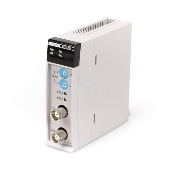
Chapter 3. Configuration Chapter 3 Configuration Part names and functions EH-LNK Name and function of each part Type Approx. 0.15 kg Weight 1] Lock button Dimensions(mm) 2] Module information display 3] Station No. setting switch (10-digits) 4] Station No. setting switch (1-digits) 5] Error display clearance switch 6] Reset switch... -
Page 12: Module Information Display Led
Chapter 3. Configuration Module information display LED Descriptions of the module information display for all LEDs are provided in table 3.1. Table 3.1 Module Status display LED Outlook Name Color Contents Green Blinking when data is being transmitted. CPU LINK EH-LNK Green Blinking when data is being received. -
Page 13: Chapter 4. Basic Cpu Link Operations 4-1 To
Chapter 4. Basic CPU Link Operations Chapter 4 Basic CPU Link Operations System Configuration An example of a CPU link module configuration is shown is figure 4.1. It is possible to connect up the EH-LNK together with upper level H series CPU link modules (LINK-H, LINK-SH, LINK-02H, etc.) As indicated in figure 4.1, it is possible to use both upper level H series CPU link modules and CPU modules in a link system loop. -
Page 14: Cpu Link Functions
Chapter 4. Basic CPU Link Operations CPU link functions A transmission area and a receiving area are assigned to the CPU's link area, and all link operations are performed via these areas. The link areas can be assigned arbitrarily in units of 16 points (1 word) for each CPU. - Page 15 Chapter 4. Basic CPU Link Operations 2) Link area identification When two CPU link modules have been installed, the first and second link areas are identified in accordance with their installation position. The slots are counted in 0, 1, 2 sequence from the right-hand side of the CPU, and the CPU link module with the smallest number is assigned as the first unit, with the other unit assigned as the second CPU link module.
- Page 16 Chapter 4. Basic CPU Link Operations 3) Precautions related to assignment duplication Link areas assigned in local stations will become the areas for transmitting to other stations, and the remaining area will become the area for receiving from other stations, in accordance with link area assignment.
-
Page 17: Function For Accessing Other Stations
Link data refresh time The amount of time required for the EH-150 link module to update link data is calculated in the following manner. However, this is only a rough estimate and does not necessarily apply when transmission errors and other errors are triggered. -
Page 18: Method Of Confirming Link Data Validation
Chapter 4. Basic CPU Link Operations Method of confirming link data validation 4.5.1 Link Error Flag Area When reading area data assigned to other stations, it is necessary to confirm that each station's link module is operating normally and that the CPU is running correctly at the very least. The method for doing this is by monitoring the link operation station flags (WRF05E to WRF08E and WRF145 to WFR148) and the CPU status flags (WRF0E9 to WRF0F8 and WRF149 to WFR158) and confirming all are set at ON (normal operations) before reading the assigned area data. -
Page 19: Example Of Effective Check Of Link Data
Chapter 4. Basic CPU Link Operations 4.5.2 Example of Effective check of Link Data Figure 4.7 shows the example which CPU module of link station No.0 checks the effective of link data (receive area) from other stations. ST32 ST63 Figure 4.7 CPU link configuration R7E4 WM0 :ST. -
Page 20: Chapter 5. Installation And Start-Up 5-1 To
Chapter 5. Installation and start-up Chapter 5 Installation and start-up Installation 5.1.1 Installation position The available slot for EH-LNK is slot 0, 1 or 2 of basic base at maximum 2 times. Slot No. Available slot 2 units can be mounted at maximum. Slot No. -
Page 21: Loading The Module
Chapter 5. Installation and start-up 5.1.2 Loading the Module (1) Installing 1] Hook the claw at the lower section of the module to the hole in the base. 2] Press in the upper side of the module until it clicks. Note 1: After loading the module, check to make sure it does not come out. -
Page 22: Cable Connections
Chapter 5. Installation and start-up 5.1.4 Cable connections The coaxial cable connections between CPUs are shown in figure 5.3. As shown in figure 5.3, the TXD is connected to the opposing RXD to ensure that only one cable is sued for the entire link system. -
Page 23: Coaxial Cable Shielding Process
Chapter 5. Installation and start-up 5.1.6 Coaxial cable shielding process Figure 5.5 shows the shielding line of a shielded coaxial cable when two EH-LNK units are installed on the basic base (EH-BS3.) The shielding line is only earthed on the RXD (receiving) side as a basic principle. However, this depends on the noise environment prevalent with the user, so the cable on the TXD (transmission) side may also be used without cutting off the shielding line. -
Page 24: Precautions When Wiring Coaxial Cables
Chapter 5. Installation and start-up 5.1.7 Precautions when wiring coaxial cables Observe the following precautions when wiring coaxial cables for transmission purposes between CPU link modules to avoid the effects of noise and to increase reliability. (1) Use a different route to power lines and signal cables when wiring coaxial cables for transmitting between CPU link modules. -
Page 25: Start-Up
Chapter 5. Installation and start-up Start-up The procedure for starting up a link system is explained below. 1. Although there are no restrictions on the order in which the power supply to each station must be switched on when starting up a link system, link operations will not commence until the power has been switched on to station No.0 (the master station.) Create the program used for controlling and computing the link data after the master station's participation flag has been set at ON. -
Page 26: Errors
Chapter 6. Errors and error recovery Chapter 6 Errors and error recovery Errors If an error occurs with the link module or an abnormality arises with the transmission route, the status display LED will indicate the error. The error information will also be set in the special CPU internal output related to the relevant link module (R7DE, WRF007, WRF0E0 to WRF19F.) "1"... -
Page 27: Error Displays
Chapter 6. Errors and error recovery Error displays The LED displays when the following errors occur are explained below. (1) Normal operations (LED display status and module status) Status of LED indication & Condition of Link Module CPU LINK EH-LNK The RUN LED lights. -
Page 28: Troubleshooting
Chapter 6. Errors and error recovery Troubleshooting This section provides a flowchart on the procedures for troubleshooting when recovering errors and when errors occur. As the EH-LNK is equipped with e bypass function, it is possible to replace modules with units other than link modules without amending the architecture of the link system. - Page 29 Chapter 6. Errors and error recovery (2) Transmission route cut-off ERR LED - Error information of own station : bit8 ON Flicker at 0.5 sec intervals - Cut-off station No. : bit0 to bit7 * The local station error information Check to ascertain if the transmission route has been cut off.
- Page 30 Chapter 6. Errors and error recovery Duplicated station No.s ERR LED - Error information of own station : Flicker at 0.5 sec intervals bit8 to b11 all OFF Check to ascertain if there is a station sharing the same station No. as the one displaying an error.
- Page 31 Chapter 6. Errors and error recovery ERR LED - Error information of own station : bit9 ON Flicker at 0.5 sec intervals Check the station No. setting. Has the station No. been set between 0 and 63? Set the correct station No. and then switch the power off and on (or press the reset switch.) Replace the module with a spare one,...
- Page 32 Chapter 6. Errors and error recovery ERR LED - Error information of own station : bit9 ON Flicker at 0.5 sec intervals Check the link area assignment setting. Is the ERR LED on Other stations illuminated or blinking? Correctly set the assignment range between WL0000 to 03FF or WL1000 to WL13FF.
- Page 33 Chapter 6. Errors and error recovery (7) Transmission error (CRC error, overrun) ERR LED - Error information of each station : bit14 ON Flicker at 1 sec intervals Run a loop-back check (refer to section 7.3.) Has an error occurred in the loop-back check? Does it happen frequently? It may be assumed that this is a...
- Page 34 Chapter 6. Errors and error recovery (8) Peripheral data receiving time-out, sum error, address error, response time-out ERR LED - Error information of own station : bit13 ON - Error information of each station : bit13 ON Flicker at 1 sec intervals - Error information of own station : bit13 ON - Error information of each station : bit15 ON Run a loop-back check (refer to...
-
Page 35: Chapter 7. Maintenance And Inspections 7-1 To
Chapter 7. Maintenance and Inspections Chapter 7 Maintenance and Inspections Daily inspections Check the following items to ensure the operational status of the equipment. Refer to Chapter 6 (Error Displays and Troubleshooting) for further details on errors. Table 7.1 Daily inspection items Item Normal Abnormal... -
Page 36: Loop-Back Check
Chapter 7. Maintenance and Inspections Loop-back check Run a loop-back check in accordance with the procedure explained below when normal operations are not possible during test operations of the link system, and when errors occur after start-up, resulting in link system operations being suspended. - Page 37 It is recommended that a product equivalent to the shielded 5D2VTXE (manufactured by Fujikura Densen) is used as the transmission coaxial cable with EH-150 CPU link modules. The method of processing the ends of this cable is explained below. Note that this chapter is only to be used as reference material. For further information, contact the manufacturers of the cables and connectors directly.
- Page 38 Appendix. Processing the ends of the coaxial cable Appendix 2 Processing the outer sheath and outer shield Working STEP Description of work Remark External shield Remove the cable covering as shown in the diagram pre-processing below, and expose the external semi-conductor. External shield Approx.
- Page 39 Appendix. Processing the ends of the coaxial cable Working STEP Description of work Remark Attaching Cover it with the vinyl tube as shown in the diagram vinyl wir below. L / 2 Processing the Peel back 5mm of the vinyl wire. end of the vinyl wire Attach a compression terminal.
- Page 40 Appendix. Processing the ends of the coaxial cable Appendix 3 Processing the inner sheath and inner shield The method of connecting and attaching the coaxial cable connector to the coaxial cable is shown below. It is recommended that a product equivalent to the BNC-P-5DV (Manufactured by Hirose Inc.) is used. (Refer to the diagram in Appendix.3.) Plug (BNC-P-5DV) Figure Appendix.3 Coaxial cable connector...
- Page 41 Appendix. Processing the ends of the coaxial cable Working STEP Description of work Remark End processing Remove the insulation. Remove the insulation, but leave approximately 5mm from the end of the clamp. Approx. 5mm (insulator) Approx. 5mm (center conductor) *Take care not to damage the central semi-conductor when removing the insulation.
- Page 42 Appendix. Processing the ends of the coaxial cable Working STEP Description of work Remark Attaching Insert it in the plug shell after soldering. (10) plug shell Check to ascertain that the connection areas on the central semi- conductor and the terminal are not bent when inserting them. Good No good Gasket...