Hitachi EH-150 Applications Manual
Ethernet module 2 eh-eth2
Hide thumbs
Also See for EH-150:
- Engineering manualline (9 pages) ,
- Applications manual (58 pages) ,
- Applications manual (42 pages)

Related Manuals for Hitachi EH-150


Summary of Contents for Hitachi EH-150
- Page 1 HITACHI PROGRAMABLE CONTROLLER Ethernet Module 2(EH-ETH2) APPLICATION MANUAL NJI-543C (X)
- Page 2 Warranty period and coverage The product warranty period will be one year after the product has been delivered to the location designated in the order. If a malfunction occurs within the warranty period even though the product has been used within the range of correct conditions according to the product specifications given in this document, we will exchange or repair the defective part free of charge.
- Page 3 Safety Precautions Read this manual and related documents thoroughly before installing, operating, performing preventive maintenance or performing inspection, and be sure to use the unit correctly. Use this product after acquiring adequate knowledge of the unit, all safety information, and all cautionary information. Also, make sure this manual enters the possession of the chief person in charge of safety maintenance.
- Page 4 2. About wiring REQUIRED Always perform grounding (FE terminal). If grounding is not performed, there is a risk of electric shocks and malfunctions. CAUTION Connect power supply that meets rating. If a power supply that does not meet rating is connected, fire may be caused. The wiring operation should be performed by a qualified personnel.
- Page 5 4. About preventive maintenance DANGER Do not connect the of the battery in reverse. Also, do not charge, disassemble, heat, place in fire, or short circuit the battery. There is a risk of explosion or fire. PROHIBITED Do not disassemble or modify the unit. These actions may result in fire, malfunction, or malfunction.
- Page 6 Revision History NJI No. DATE CONTENTS NJI543(X) Oct.2009 First release NJI543A(X) May.2010 Input of IP address is added to section 6.3 "Connection with LADDER EDITOR for Windows®". NJI543B(X) Oct.2010 Procedure of uploading of setup file (setup.dat) of EH-ETH is added to section 5.4.4 "Downloading and Uploading of Setup file"...
-
Page 7: Table Of Contents
Table of contents Chapter 1 Introduction 1-1 to 1-4 Before to use.............................. 1- 1 Outline ............................... 1- 2 Feature ............................... 1- 2 Notes to use ............................... 1- 3 Term and abbreviation..........................1- 4 Chapter 2 System structure Chapter 3 Specifications 3-1 to 3-2 General Specifications.......................... - Page 8 Chapter 7 Automatic Sending/Receiving function (ASR) 7-1 to 7-25 ASR ................................7- 1 7.1.1 Automatic data sending........................ 7- 1 7.1.2 Automatic data receiving ......................7- 2 Presetting ..............................7- 4 7.2.1 Open connection .......................... 7- 5 7.2.2 Close connection.......................... 7- 10 ASR with user program ..........................
- Page 9 Sample program lists To set Ethernet parameters ........................5- 15 To check Ethernet parameters ........................5- 17 To open the connection to other station..................... 7- 8 To close the connection to other station ....................7- 12 To close the connection with "Close mode control" enabled..............7- 15 To refresh receiving area with "Optional receiving mode"................
-
Page 10: Chapter 1 Introduction 1-1 To
Chapter 1 Introduction We appreciate that you have selected the HITACHI Programmable Controller (PLC) EH-150 Series. This application manual describes how to properly operate the EH-150 Ethernet Module. Please read this manual carefully to familiarize yourself with the procedures respectively of installation, operation, and maintenance and check. -
Page 11: Outline
This product supports production control and system operation monitor, equipment monitor and maintenance by connecting PLC to information network. EH-ETH2 (this module) can be mounted onto the basic base of EH-150 system and is the communication module can be connected EH-150 system to Ethernet comforms to IEEE802.3. -
Page 12: Notes To Use
Chapter 1 Introduction Notes to use (1) Please note the master CPU type to control this module Table 1.3 supported CPU CPU type supported or not EH-CPU104 not supported EH-CPU208 not supported EH-CPU308 not supported EH-CPU316 not supported EH-CPU448 supported EH-CPU516 supported EH-CPU548... -
Page 13: Term And Abbreviation
Chapter 1 Introduction Term and abbreviation Table 1.4 shows the term and abbreviation in this manual. Table 1.4 Term and abbreviations Term / abbreviation Description Ethernet parameters This is general terms of parameter including IP address, task code logic port number etc. This abbreviation of Automatic Sending/Receiving ASR connection This is connection which is called message communication for data... -
Page 14: Chapter 2 System Structure
Chapter 2 System structure Chapter 2 System structure Figure 2.1 shows an example of FA system consisting of combined EH-150 communication systems. (1): EH-ETH2 (2): EH-LNK (3): EH-RMD (4): EH-IOCD (5): Hitachi inverter (6): Hitachi servo Ethernet network CPU LINK DeviceNet network Figure 2.1... -
Page 15: Chapter 3 Specifications 3-1 To
Chapter 3 Specifications Chapter 3 Specifications General Specifications The general specifications of this module are show in Table 3.1. Table 3.1 General Specifications Items Specifications Dielectric withstand voltage 250 V DC between the communication signal and case ground (FE) Internal current consumption 5 V 470 mA 0 to 55 °C Operating ambient temperature... -
Page 16: Functional Specifications
Chapter 3 Specifications Functional Specifications The functional specifications of this module are shown in Table 3.3. Table 3.3 Functional Specifications Items Specifications - Set up EH-ETH2’s Communication parameter with the dedicated software Configuration “EH-ETH2 Configurator”. - The configuration for IP address setting and Taskcode communication should be (*1) done at Configuration mode. -
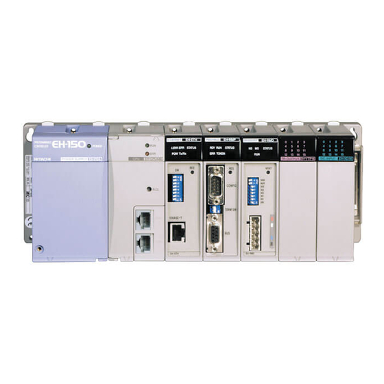
Page 17: Chapter 4 System Equipment 4-1 To
Chapter.4 System equipment Chapter 4 System equipment EH-ETH2 Name and function of each parts Type 0.12 kg (0.26 Lb.) Weight Dimensions (mm (in.)) 7) Lock button 1) LED cover 2) E.CLR switch 3) Reset switch 4) Dip switch 5) RS-232C connector 6) Ethernet connector LINK Transfer... -
Page 18: Operating Mode
Chapter.4 System equipment Operating mode Operation mode of EH-ETH2 is set by a dip switch on the front panel. The mode change is effective after completion of EH-ETH2 initialization. The dip switch setting is effective only when power on or the reset button pressed. -
Page 19: Led Indications
Chapter.4 System equipment LED indications Figure 4.1 shows out view of the LED cover. ETHERNET EH-ETH2 Figure 4.1 Out view of the LED cover Table 4.3 shows LED indications. Table 4.3 LED indications Name Indication Description The module is in Normal operation mode. Blinking The module is in Utility mode. -
Page 20: Sts Led
Chapter.4 System equipment 4.2.1 STS LED STS LED blinks with turning on ERR LED or IER LED, when EH-ETH2 has been detected an error. Table 4.4 shows Error class corresponding between STS LED’s blinking pattern and LED turns on concurrently with. -
Page 21: Chapter 5 Configuration Of Communication Parameters 5-1 To
Chapter 5 Configuration of Communication parameters Chapter 5 Configuration of communication parameters Communication parameters consist of Ethernet parameters and ASR parameters. Ethernet parameters It is required to configure the Ethernet parameters to this module before to start communication. The Ethernet parameters are saved by the retained memory of this module as the part of setup file. The detail of the Ethernet parameters is shown in Table 5.1. -
Page 22: Configuration Of Ethernet Parameters Using Eh-Eth2 Configurator
Chapter 5 Configuration of Communication parameters Configuration of Ethernet parameters using EH-ETH2 Configurator Communication parameters are configured or confirmed via EH-ETH2 Configurator. Table 5.2 The list of the items can be configured by EH-ETH2 Configurator Items Section number to refer (1) Ethernet parameters Section 5.2.7 IP address of self station... -
Page 23: Configuration
Chapter 5 Configuration of Communication parameters 5.2.2 Configuration Please connect PC and HUB, HUB and EH-ETH2 with LAN cable. The example in Figure 5.2 shows the smallest network by the explanation for convenience. PLC / EH-ETH2 Figure 5.2 Example of network 5.2.3 Network Setting on PC side At the network configuration of Figure 5.2, to access EH-ETH2 Configurator, the setting of PC must be the... - Page 24 Chapter 5 Configuration of Communication parameters The below explains the changing procedure of network setting at PC side. Furthermore, PC's OS is Windows2000 or later. - IP address (1) Open [Network] in control panel. Click [TCP/IP] protocol and [Property] button. (2) Select [IP address] tag, input [192.168.0.128] in IP address.
-
Page 25: Setting Of Dip Switch
Chapter 5 Configuration of Communication parameters 5.2.4 Setting of Dip switch To set Ethernet parameters by EH-ETH2 Configurator, set No.1 ON, No.2,3 OFF of dip switch. In this mode, No.4 to 8 means lower 5 bits of IP address. Furthermore remained higher 27 bits of IP address is fixed. -
Page 26: Access To Eh-Eth2 Configurator
Chapter 5 Configuration of Communication parameters 5.2.5 Access to EH-ETH2 Configurator When PLC is power on, STS LED turns on or blinks. You can access EH-ETH2 Configurator at both conditions. We recommend setup the I/O assignment on CPU at first. ETHERNET EH-ETH2 In the case that it is done with I/O correctly... -
Page 27: Initial Screen Structure Of Eh-Eth2 Configurator
Chapter 5 Configuration of Communication parameters 5.2.6 Initial screen structure of EH-ETH2 Configurator Figure 5.7 shows the initial screen of EH-ETH2 Configurator. 1. menu bar 2. work area Figure 5.7 The initial screen of EH-ETH2 Configurator The initial screen of EH-ETH2 Configurator consists of menu bar and work area. 1. -
Page 28: Configuration On Ethernet Parameters Window
Chapter 5 Configuration of Communication parameters 5.2.7 Configuration on Ethernet parameters window On Ethernet parameters window, configure or confirm Ethernet parameters. (1) Window structure Figure 5.8 shows Ethernet parameters window. 1. menu bar 2. input area 10-1) 11-1) 10-2) 11-2) 10-3) 11-3) 3. - Page 29 Chapter 5 Configuration of Communication parameters (2) Input items Input items that can be configured in Ethernet parameters window are shown in Table 5.6. Table 5.6 Input items of Ethernet parameters window Name Description Range for setting IP Address Set MAC Address To confirm the MAC address of EH-ETH2 Confirming only...
-
Page 30: Ethernet Parameters Setting Error Code
Chapter 5 Configuration of Communication parameters 5.2.8 Ethernet parameters setting error code The list of error code of Ethernet parameters setting is shown in Table 5.8. Table 5.8 The list of error code during the IP address setting Error Display comment Causes Code Operation mode: Is not Configuration mode. -
Page 31: Configuration Of Ethernet Parameters By User Program
(3) Setting and referring the table value of Ethernet parameters The dedicated commands (FUN200 on EH-150 series, XYRW on EHV-CPU series) should be used for setting or referring the value of Ethernet parameters of this module. These commands handle the data transfer between internal memory area of CPU and the retained memory of this module. - Page 32 Chapter 5 Configuration of Communication parameters (4) The configuration procedure of Ethernet parameters table The configuration procedure of Ethernet parameters shown in Table 5.11 is described here. And also the check procedure is described here. Table 5.11 Example of the configuration Items Setting value The area to set...
- Page 33 Chapter 5 Configuration of Communication parameters (b-1) FUN200 command (for EH-150 series) The notation of the FUN200 command specification and FUN200 usage for this module are described here. FUN200 command Format FUN 200 ( s ) Parameter Starting I/O No. of the s parameter area Function - This command handles Ethernet parameters using extended XY area between CPU module and this module.
- Page 34 Chapter 5 Configuration of Communication parameters (b-2) XYRW command (for EHV-CPU series) The notation of the XYRW command specification and XYRW usage for this module are described here. XYRW command Format XYRW ( s, t ) Parameter Starting I/O No. of the s parameter area, starting I/O No. of the t parameter area Function - This command handles Ethernet parameters using extended XY area between CPU module and this module.
-
Page 35: To Set Ethernet Parameters
Chapter 5 Configuration of Communication parameters Sample program 1 To set Ethernet parameters Slot No. EH-ETH2 (for EH-CPU) R7E3 To set s parameter area (00001) WR003 = H3 The request of Ethernet Parameters putting WR004 = H200 To set the target area (Unit 0, Slot 2) ADRIO = (WR005, R100) To configure R100 as the control bit I/O No. - Page 36 Chapter 5 Configuration of Communication parameters Sample program 1 To set Ethernet parameters Slot No. EH-ETH2 (for EHV-CPU) R7E3 To set s parameter area (00001) WR003 = H3 The request of Ethernet Parameters putting WR004 = H200 To set the target area (Unit 0, Slot 2) DR005 = ADR (WM100) To configure WM100 as the starting area of WR007 = 55...
-
Page 37: To Check Ethernet Parameters
Chapter 5 Configuration of Communication parameters Sample program 2 To check Ethernet parameters Slot No. EH-ETH2 (for EH-CPU) R7E3 To set s parameter area (00001) WR013 = H1 The request of Ethernet Parameters getting WR014 = H200 To set the target area (Unit 0, Slot 2) ADRIO = (WR015, R110) To configure R110 as the control bit I/O No. - Page 38 Chapter 5 Configuration of Communication parameters Ethernet parameters read by Sample program 2 are stored in the area below. WM140 Own IP Address (upper) WM141 (lower) WM142 Subnet mask (upper) WM143 (lower) WM144 IP Address for Diagnosis (upper) WM145 (lower) WM146 Port No.
-
Page 39: Configuration Of Asr Parameters
Chapter 5 Configuration of Communication parameters Configuration of ASR parameters There are 3 kinds of configuration items for ASR parameters as shown in Table 5.12. Table 5.12 The classification of ASR parameters Class Outline Description ASR General Information General setting for all connections. ASR Connection Setting Setting for every connection ASR I/O Area Setting... - Page 40 Chapter 5 Configuration of Communication parameters (2) Input items Input items that can be configured in ASR parameters window are shown in Table 5.13. Table 5.13 The list of items of ASR General Information Name Description Range for setting ASR General Information To select the enable or disable base on the AEN bit configuration of Always Enable, Module control register (MDCR) whether the ASR is valid without...
-
Page 41: Configuration Of Asr Connection
Chapter 5 Configuration of Communication parameters 5.4.2 Configuration of ASR connection The procedure of setting for ASR connection (1) Window structure ASR Connection Setting window is shown in Figure 5.11. 1. Menu bar 2. Connection tab 3. Input area 4. Operation area Figure 5.11 ASR Connection Setting window 1. - Page 42 Chapter 5 Configuration of Communication parameters (2) Input items Input items that can be configured in ASR Connection Setting window are shown in Table 5.15. Table 5.15 The list of items of ASR connection configuration Name Description Range for setting Own Station Usage To specify the usage of connection.
- Page 43 Chapter 5 Configuration of Communication parameters (3) Operation buttons The window has the four operation buttons shown below. Table 5.17 Operation buttons of ASR Connection Setting window Name Description To connect to EH-ETH2. At this time, the present values are overwrtiten in Online each input boxes.
-
Page 44: Configuration Of Asr I/O Area
Chapter 5 Configuration of Communication parameters 5.4.3 Configuration of ASR I/O area When using ASR connections, it is required to specify the I/O area in the CPU module as the sending source area and the receiving destination area. The configuration procedure for these usages is described here. - Page 45 Chapter 5 Configuration of Communication parameters (2) Input items Input items that can be configured in ASR I/O Area Setting window are shown in Table 5.18. Table 5.18 The list of items of ASR I/O area configuration Name Description Range for setting Receive Area Information To specify the I/O for the receiving area.
- Page 46 5. The valid combination of CPU and the range of I/O areas is shown in Table 5.20. Table 5.20 The Table of valid combination of CPU and the range of I/O area EHV-CPU EH-150 Usage Length Type 16 / 32 / 64 remarks...
-
Page 47: Downloading And Uploading Of Setup File
Chapter 5 Configuration of Communication parameters 5.4.4 Downloading and Uploading of Setup file A user can download to host computer (PC or WS) via EH-ETH2 Configurator. A user can also upload a stored setup.data file to EH-ETH2 from host computer. You do not need to change an operation mode (dip switch setting) when you download the setup file. - Page 48 Chapter 5 Configuration of Communication parameters (2) Operation buttons The explanations of the items on the window are shown below. Table 5.21 Setup file frame parameter Name Description Download Download To store a setup file in the PC. When you click this button, the save as dialogue will be displayed. Specify the file name to store. Upload File Name The file name and path of the setup file for uploading to EH-ETH2 is displayed.
-
Page 49: Asr Parameters Setting Error Code
Chapter 5 Configuration of Communication parameters 5.4.5 ASR parameters setting error code The list of error code of ASR parameters setting is shown in Table 5.22. Table 5.22 ASR parameters setting error code Error Comment Cause code (*1) 2101 General information (No.n): Port No. is incorrect. Illegal value or character is set for ASR connection n port number... -
Page 50: Chapter 6 Task Code Communication 6-1 To
Chapter 6 Task code communication Chapter 6 Task code communication H/EH series PLC has a communication protocol called task code, which enables easy communication between host computer and EH-ETH2. Features of task code communication - No need user program for task code communication. - A Host computer is able to up/download a user program to/from a CPU module using the task code. -
Page 51: Frame Format
Chapter 6 Task code communication 6.1.2 Frame format The task code format of EH-ETH2 is shown in Figure 6.2. If you make an application program for host computer, you should follow this format, which is different from the standard RS-232C protocol. The data must be binary. -
Page 52: H/Eh Series Network Address
Chapter 6 Task code communication 6.1.3 H/EH series network address At H/EH series network system shown in Figure 6.3, you must specify the CPU address according to the LUMP address rule as below. Station 0 ETH2 Ethernet Loop α Host Station 5 Station 0 ETH2... -
Page 53: Operative Example For Task Code Transmission
Chapter 6 Task code communication 6.1.4 Operative example for task code transmission An example for request / reply task code transmission is below. request task code reply task code 00 12 FFFF0000 1000 00 12 FFFF0000 00 10 ***** Task code to read CPU status Detail information of CPU status Network address (LUMP) Requested task code... -
Page 54: Task Code Port
Chapter 6 Task code communication Task code port EH-ETH2 has four logical ports for task code communication. Task code port supports TCP and UDP of data link layer. Table 6.3 shows the comparison to use. Table 6.3 Task code port Compression Item Host side: Need... -
Page 55: Connection With Ladder Editor For Windows
Chapter 6 Task code communication Connection with LADDER EDITOR for Windows® You can program CPU module via EH-ETH2 with LADDER EDITOR for Windows®. This chapter explains at the setting of EH-ETH2 and PC shown in Table 6.4. The setting of EH-ETH2 is default value. -
Page 56: Host Name Setting
Chapter 6 Task code communication 6.3.2 Host name setting When the connecting station is specified by the host name, the setting of the Hosts file is needed in addition to the setting of LADDER EDITOR for Windows®. - Editing of Hosts file Edit the file "host"(no extended code) in the directly (usually in ¥windows) is installed by the following process. - Page 57 Chapter 6 Task code communication - Setting of LADDER EDITOR for Windows® (1) Open LADDER EDITOR for Windows® and go off-line mode. (2) Choose [Environment Set] in [Utility] menu in the offline mode. (3) Choose [Communication]dialog box. A) Communication type : Ethernet B) Host name : EH-ETH2 (Name in Hosts file )
-
Page 58: Connection With Control Editor
Chapter 6 Task code communication Connection with Control Editor You can program CPU module via EH-ETH2 with Control Editor. This chapter explains at the setting of EH-ETH2 and PC shown in Table 6.5. The setting of EH-ETH2 is default value. IP address of PC should be set at your network environment. Table 6.5 Setting Setting Item... -
Page 59: Chapter 7 Automatic Sending/Receiving Function (Asr) 7-1 To
Chapter 7 Automatic Sending/Receiving function (ASR) Chapter 7 Automatic Sending/Receiving function (ASR) EH-ETH2 has ASR function. The detailed information is mentioned as follows. 7.1.1 Automatic data sending An automatic sending function is a function to transmit the data of CPU module to other node. The outline of this function is shown as Figure 7.1. -
Page 60: Automatic Data Receiving
Chapter 7 Automatic Sending/Receiving function (ASR) (2) Sending area (*1) Sending area can be specified in EH-ETH2 Configurator of “ASR I/O Area (Connection n ) Setting”. One connection can handle up to 10 sending areas. (One sending area is called as “Entry”) In case of sending several kinds of I/O areas, they are once sent to a sending buffer according to the setting in EH-ETH2 Configurator. - Page 61 Chapter 7 Automatic Sending/Receiving function (ASR) (2). Receiving area The receiving area can be specified only by “ASR I/O Area (Connection N) Setting” in EH-ETH2 Configurator. The receiving area can be defined every ASR connection. Available I/Os are word I/Os except WX. EH-ETH2 CPU module Receive Area Information...
-
Page 62: Presetting
Chapter 7 Automatic Sending/Receiving function (ASR) Presetting Before the data communication, you have to establish connection against to the other port. Here after, an enabled connection is called as “opened connection”, and a disabled connection is called as “closed connection”. Caution EH-ETH2 has 10 connections. -
Page 63: 7.2.1 Open Connection
Chapter 7 Automatic Sending/Receiving function (ASR) 7.2.1 Open connection The procedure for opening connection is shown as Figure 7.7. Host PC EH-ETH2 Host PC EH-ETH2 (A-1) (B-1) (A-2) (B-2) (A-3) (B-3) (A) In case of active open setting (B) In case of passive open setting (A) In case EH-ETH2 is in active open EH-ETH2 Description... - Page 64 Chapter 7 Automatic Sending/Receiving function (ASR) There are two ways for EH-ETH2 (specified as active) to open ASR connection. To send a request to open automatically after initializing of EH-ETH2 completed. To send a request to open by user program. Caution ASR information must be set correctly to open ASR connection.
- Page 65 Chapter 7 Automatic Sending/Receiving function (ASR) EH-ETH2 is able to request to open connection to other stations by setting “Request to open bit” to high. The procedure to open ASR connection 1 is shown as Figure 7.8. Register name C1CSR.OPC1 CNCR.OPN1 C1ESR.OE1 EC1CR.OEC1...
-
Page 66: To Open The Connection To Other Station
Chapter 7 Automatic Sending/Receiving function (ASR) Sample program 3 To open the connection to other station Slot No. EH-ETH2 (for EH-CPU) (00001) Parameter area setting of FUN201(s) for reading out R7E3 WM003 = H2 Request to read out SR WM004 = H2F Area setting (unit:0, slot:0) ADRIO = (WM005, R100) Control bit address is R100... - Page 67 Chapter 7 Automatic Sending/Receiving function (ASR) Sample program 3 To open the connection to other station Slot No. EH-ETH2 (for EHV-CPU) (00001) Parameter area setting of SCRW for reading out SR R7E3 Request to read out SR WM003 = H2 Area setting (unit:0, slot:0) WM004 = H2F Transmission I/O address is starting from WM10...
-
Page 68: 7.2.2 Close Connection
Chapter 7 Automatic Sending/Receiving function (ASR) 7.2.2 Close connection The procedure for closing connection is shown as Figure 7.9. Host PC EH-ETH2 Host PC EH-ETH2 (A-1) (B-1) (A-2) (B-2) (A-3) (B-3) (A-4) (B-4) (A) In case EH-ETH2 requests to close connection (B) In case host PC requests to close connection (A) In case EH-ETH2 requests to close connection EH-ETH2... - Page 69 Chapter 7 Automatic Sending/Receiving function (ASR) The conditions to close connection are ; (1) EH-ETH2 receives a request to close from user program in own station during connection opened. (2) EH-ETH2 receives a request to close from other stations during connection opened. The following description is regarding the way to close connection from user program.
-
Page 70: To Close The Connection To Other Station
Chapter 7 Automatic Sending/Receiving function (ASR) Sample program 4 Slot No. To close the connection to other station (for EH-CPU) EH-ETH2 (00001) R7E3 Setting parameter of FUN201(s) for reading out SR WM003 = H2 Request to read out SR WM004 = H2F Area setting (unit:0, slot:0) ADRIO = (WM005, R100) Control bit address is R100... - Page 71 Chapter 7 Automatic Sending/Receiving function (ASR) Sample program 4 To close the connection to other station Slot No. EH-ETH2 (for EHV-CPU) (00001) R7E3 Setting parameter of SCRW(s) for reading out SR WM003 = H2 Request to read out SR WM004 = H2F Area setting (unit:0, slot:0) DM005 = ADR (WM10) Transmission I/O address is starting from WM10...
- Page 72 Chapter 7 Automatic Sending/Receiving function (ASR) (b) CMCR.CMn = 1 (“Close mode control” is enabled. “n” is ASR connection number) Even if EH-ETH2 receives a request to close from other station, EH-ETH2 does not close the connection unless a user program is executed for closing the connection. The time chart to close connection 4 is shown in Figure 7.12.
-
Page 73: To Close The Connection With "Close Mode Control" Enabled
Chapter 7 Automatic Sending/Receiving function (ASR) Sample program 5 To close the connection with "Close mode control" enabled Slot No. EH-ETH2 (for EH-CPU) R7E3 (00001) M293 = 1 “Close mode control” for connection 4 is enabled. (00002) R7E3 Setting parameter of FUN201(s) for reading out SR. WM003 = H2 Request to read out SR WM004 = H2F... - Page 74 Chapter 7 Automatic Sending/Receiving function (ASR) Sample program 5 To close the connection with "Close mode control" enabled Slot No. EH-ETH2 (for EHV-CPU) R7E3 (00001) M293 = 1 “Close mode control” for connection 4 is enabled. (00002) R7E3 Setting parameter of SCRW(s) for reading out SR. WM003 = H2 Request to read out SR WM004 = H2F...
-
Page 75: Asr With User Program
Chapter 7 Automatic Sending/Receiving function (ASR) ASR with user program Without any user program, EH-ETH2 is able to send / receive data by using cyclic sending and receiving function. In addition to this function, you can achieve more precise data transmission by using above function with user program. -
Page 76: 7.3.1 Optional Data Receiving
Chapter 7 Automatic Sending/Receiving function (ASR) 7.3.1 Optional data receiving - Receive mode is Optional receiving mode EH-ETH2 store data in receive buffer from "other station" to receiving area (CPU internal output) when user program "receive refresh permit". Outline and time chart of Optional receiving mode is shown in Figure 7.13. Data receive Normal Receive mode... - Page 77 Chapter 7 Automatic Sending/Receiving function (ASR) Time chart for connection 2 is shown as Figure 7.14. Register name Optional receiving mode EXRR. ARP2 = 1 RDCR .ARE2 C2CSR .RXC2 : By user, : By EH-ETH2 Figure 7.14 Procedure of Optional receiving (1) When receive mode is optional mode, set 1 to “receive mode change ”...
- Page 78 Chapter 7 Automatic Sending/Receiving function (ASR) The sample program uses the below internal I/O. FUN 201 parameters for reading Status Register (SR) FUN 201 parameters for writing Control Register Description Description WM0 Result (Return code) WM8 Result (Return code) WM1 System area WM9 System area WM2 System area WMA System area...
-
Page 79: To Refresh Receiving Area With "Optional Receiving Mode
Chapter 7 Automatic Sending/Receiving function (ASR) Sample program 6 Slot No. To refresh receiving area with "Optional receiving mode" (for EH-CPU) EH-ETH2 (00001) R7E3 Parameters setting of FUN201(s) for reading out SR. WM003 = H2 Request to read out SR WM004 = H2F Area setting (unit:0, slot:0) ADRIO = (WM005, R100) - Page 80 Chapter 7 Automatic Sending/Receiving function (ASR) Sample program 6 Slot No. To refresh receiving area with "Optional receiving mode" (for EHV-CPU) EH-ETH2 (00001) R7E3 Parameters setting of SCRW(s) for reading out SR. WM003 = H2 Request to read out SR WM004 = H2F Area setting (unit:0, slot:0) DM005 = ADR (WM10)
-
Page 81: 7.3.2 Event Sending
Chapter 7 Automatic Sending/Receiving function (ASR) 7.3.2 Event sending This event sending function is able to send data at any requested timing. This setting is specified in EH-ETH2 Configurator as below. Please refer to "5.4.2 Configuration of ASR connection" for further information. -
Page 82: To Execute Event Sending
Chapter 7 Automatic Sending/Receiving function (ASR) Sample program 7 Slot No. To execute event sending (for EH-CPU) EH-ETH2 (00001) R7E3 Parameters setting of FUN201(s) for reading out SR. WM003 = H2 Request to read out SR WM004 = H2F Area setting (unit:0, slot:0) ADRIO = (WM005, R100) Control bit address is R100 ADRIO = (WM006, WM10) - Page 83 Chapter 7 Automatic Sending/Receiving function (ASR) Sample program 7 To execute event sending Slot No. EH-ETH2 (for EHV-CPU) (00001) R7E3 Parameters setting of SCRW(s) for reading out SR. WM003 = H2 Request to read out SR WM004 = H2F Area setting (unit:0, slot:0) DM005 = ADR (WM10) Transmission I/O address is starting from WM10 WM007 = 13...
-
Page 84: Chapter 8 Register Structure 8-1 To
Chapter 8 Register Structure Chapter 8 Register Structure The register structures of this module are described here. EH-ETH2 has Status Register (SR) and Control Register (CR). The Status Register is for reading only and mainly set communication status of each connection. The Control Register is for writing only and used to control ASR operation. -
Page 85: Module Status Register (Mdsr)
Chapter 8 Register Structure Module status register (MDSR) EIE AVR ATR IERR ERR Bit 15-7: Reserved These bits are reserved bits. Usually "0" are set. Bit 6: Operation mode bit (OPM) The status of DIP-switch 1 is reflected on this bit. Bit6: OPM Description Normal operation mode... -
Page 86: Connection N Error Status Register (Cnesr)
Chapter 8 Register Structure Connection n error status register (CnESR) n = 1 to 6 ATE1 SNE1 RCE1 STE1 OE1 RAE1 ATE6 SNE6 RCE6 STE6 OE6 RAE6 The error condition of each connection (1 to 6) is shown in this area. Bit 15-7: Reserved These bits are reserved. - Page 87 Chapter 8 Register Structure Bit 1: Send timeout error bit (STE[6:1]) These bit the timeout condition during sending data. Bit1: STE[6:1] Description No timeout error is detected during sending data. A timeout error is detected during sending data. Method to clear: To clear these bits to "0", please set "1" to TEC[6:1] of EC1CR. Bit 0: Open error bit (OE[6:1]) These bits show the condition during opening connection.
-
Page 88: Connection N Communication Status Register (Cncsr)
Chapter 8 Register Structure Connection n communication status register (CnCSR) n = 1 to 6 OPC1 CRO1 SMF1 ERF1 RXC1 TXC1 OPC6 CRO6 SMF6 ERF6 RXC6 TXC6 The connection condition of each connection is shown in this area. Bit 15-7: Reserved These bits are reserved. -
Page 89: Control Registers
Chapter 8 Register Structure Control Registers The information to control this module operation are passed from CPU module to this module via Control area. Figure 8.2 shows the map of the control area. The control area is structured with 9 kinds of registers. Each register size is 1 word (16bits). -
Page 90: Module Control Register (Mdcr)
Chapter 8 Register Structure Module control register (MDCR) AEN IAV Bit 15-4: Reserved These bits are reserved. Please set "0" always. Bit 3: Automatic Sending/Receiving enable bit (AEN) To specify whether Automatic Sending/Receiving function is used or not. Bit3: AEN Description Request to disable Automatic Sending/Receiving function. -
Page 91: Connection Control Register (Cncr)
Chapter 8 Register Structure Connection control register (CNCR) CLS6 CLS5 CLS4 CLS3 CLS2 CLS1 OPN6 OPN5 OPN4 OPN3 OPN2 OPN1 "Open request" and "Close request" for each connection is handled using this register. Bit 15, 14, 7, and 6: Reserved These bits are reserved. -
Page 92: Ready/Event Send Control Register (Recr)
Chapter 8 Register Structure Ready/Event send control register (RECR) ASE6 ASE5 ASE4 ASE3 ASE2 ASE1 Bit 15-6: Reserved These bits are reserved. Please set "0" always. Bit 5-0: Event send request bit (ASE[6:1]) This bit works as an Event send request bit. Bit5-0: ASE[6:1] Description (1) Request to clear Transmit complete bit (TXC) of Connection n... -
Page 93: Error Clear 1 Control Register (Ec1Cr)
Chapter 8 Register Structure Error clear 1 control register (EC1CR) TEC6 TEC5 TEC4 TEC3 TEC2 TEC1 OEC6 OEC5 OEC4 OEC3 OEC2 OEC1 This register is used for to clear the bits related to connection error. Bit 15, 14, 7 and 6: Reserved These bits are reserved bits. -
Page 94: Error Clear 3 Control Register (Ec3Cr)
Chapter 8 Register Structure Error clear 3 control register (EC3CR) SNC6 SNC5 SNC4 SNC3 SNC2 SNC1 RCC6 RCC5 RCC4 RCC3 RCC2 RCC1 This register is used for to clear the bits related to connection error. Bit 15, 14, 7 and 6: Reserved These bits are reserved bits. - Page 95 Chapter 8 Register Structure Table 8.1 The list of registers Status Registers Bit name Reg. name I/O No. IERR MDSR ATE1 SNE1 RCE1 RAE1 STE1 C1ESR ATE2 SNE2 RCE2 RAE2 STE2 C2ESR ATE3 SNE3 RCE3 RAE3 STE3 C3ESR ATE4 SNE4 RCE4 RAE4 STE4 C4ESR ATE5 SNE5 RCE5 RAE5...
-
Page 96: How To Access Registers
Chapter 8 Register Structure How to access registers You use the dedicated commands (FUN201 for EH-CPUs, SCRW for EHV-CPUs) to access EH-ETH2 register. The notation of these commands specification and the usage for this module are described here. FUN201 command Format FUN 201 ( s ) Parameter... - Page 97 Chapter 8 Register Structure SCRW command Format SCRW ( s, t ) Parameter Starting I/O No. of the s parameter area, Starting I/O No. of the t parameter area Function These are the commands to access registers. - This is the command to read or write Status and Control Register between CPU module and this module. - The control type supported by this command is only “With hand shaking”...
-
Page 98: Command Processing Summary And Usage
Chapter 8 Register Structure 8.3.1 Command processing summary and usage In this section, we explain the processing summary and usage of these commands with FUN201. (similar about SCRW) [Operation condition] FUN201 command is in function box without execute condition and in normal scan. When you write a data to Control Register in EH-ETH2, set control type "H0003". - Page 99 Chapter 8 Register Structure [Basic operation 2] To read Status Register (Control type "H0001"(handshake valid)) scan R7E3 (00001) WR00B = H1 WR00C = H0 ADRIO ( WR00D, R103 ) Wait execute ADRIO ( WR00E, WM110 ) instruction WR00F = 13 R7E4 (00002) R103 = 1...
- Page 100 Chapter 8 Register Structure [Basic operation 3] To read Status Register (Control type "H0002"(handshake invalid)) scan R7E3 (00001) WR00B = H2 WR00C = H2F ADRIO ( WR00D, R103 ) ADRIO ( WR00E, WM110 ) Wait execute WR00F = 13 instruction R7E4 (00002) R103 = 1...
-
Page 101: To Read Status Register
Chapter 8 Register Structure Sample program 8 To read Status Register Slot No. EH-ETH2 (for EH-CPU) When FUN201 is executed at R100=1, the value of Status Register will be putting on WM100 to WM10C. To set s parameter area R7E3 The request of Status Register getting (00001) WR003 = H2... - Page 102 Chapter 8 Register Structure Sample program 8 To read Status Register Slot No. EH-ETH2 (for EHV-CPU) When SCRW is executed at R100=1, the value of Status Register will be putting on WM100 to WM10C. To set s parameter area R7E3 The request of Status Register getting (00001) WR003 = H2...
-
Page 103: To Write To Control Register
Chapter 8 Register Structure Sample program 9 To write to Control Register Slot No. EH-ETH2 (for EH-CPU) When FUN201 command is executed at R200 = 1, WM110 to WM119 will be putting on Control Register. To set s parameter area R7E3 (00001) WR00B = H3... - Page 104 Chapter 8 Register Structure Sample program 9 To write to Control Register Slot No. EH-ETH2 (for EHV-CPU) When SCRW command is executed at R200 = 1, WM110 to WM119 will be putting on Control Register. To set s parameter area R7E3 (00001) WR00B = H3...
-
Page 105: Software Reset Function
Chapter 8 Register Structure 8.3.2 Software reset function EH-ETH2 support software reset function by the command FUN 201 or SCRW. The below is the sample program of software reset. Sample program 10 To execute software reset Slot No. EH-ETH2 (for EH-CPU) R7E3 To set s parameter area (00001) -
Page 106: Data Registers
Chapter 8 Register Structure Data Registers (*1) EH-ETH2 has data registers (WXs0, WYs1) . Data registers consist of Partial data of Status/Control Registers and flags to reset the Ethernet port. Data registers can be read or write by Arithmetic command. To WXs0 data register, the information of Module status register (MDSR) is assigned. -
Page 107: Wy Data Register
Chapter 8 Register Structure WY data register (WYs1) APR A6R A5R A4R A3R A2R A1R T4R Bit 15: Reserved This bit are reserved. Please set "0" always. Bit 14: All Ethernet port reset bit (APR) This bit is used to reset the all ethernet port. Bit14: APR Description Nothing is done. -
Page 108: Chapter 9 Maintenance, Check, Error 9-1 To
Check the module dairy or regularly in order to use EH-ETH2 in best condition and keep the system run normally. Dairy Check Check the following items in operation. AS to EH-150 series PLC, see the application manual “EH-150 application manual (NJI-280*)” or “EHV-CPU application manual (NJI-481*)”. Table 9.1 Dairy check item... -
Page 109: Error Led And Measure
Chapter 9 Maintenance, check, error Error LED and measure Following table shows the indication and the measure in case an error occurs in communication between EH-ETH2 and other station. 9.3.1 ERR confirmation by LED indication The LED indications on the module give you information about your network and the module. Table 9.3 LED indication and Error content Error content... -
Page 110: How To Turn Off Led
Chapter 9 Maintenance, check, error 9.3.2 How to turn off LED The status of ERR LED and IER LED can be read out or turned off by user program. (1) Confirm LED light User program can confirm the status (light or unlighted) of ERR and IER. The status of each LED is stored in Module status register (MDSR) in EH-ETH2. - Page 111 Chapter 9 Maintenance, check, error (c-1) By user program (for EH-CPU) User program can turn off ERR and IER LEDs. To turn each LED off, set Module control register (MDCR). Module control register (MDCR) 15 to 8 AEN IAV 0: Turn-off request cancellation ERR LED 1: Turn off request IER LED...
- Page 112 Chapter 9 Maintenance, check, error (c-2) By user program (for EHV-CPU) The below user program is the sample which converted (c-1) into for EHV-CPUs. (00001) R7E3 Set SCRW(s) parameter area. WM003 = H2 Request to SR read WM004 = H2F Set EH-ETH2 installation position(unit 0, slot0) DM005 = ADR (WM10) Set head of I/O No.
-
Page 113: Confirm Error By Status Register (Sr)
Chapter 9 Maintenance, check, error 9.3.3 Confirm error by Status Register (SR) EH-ETH2 has internally Status Register (SR) which stores communication status for each ASR connection. You can monitor this SR and program the retry circuit when the communication error occurs. See the “Chapter 8 Register Structure”... -
Page 114: Special Internal Outputs In The Cpu Module
Chapter 9 Maintenance, check, error Special Internal Outputs in the CPU module The status information on an EH-ETH2 module is stored in the special internal outputs area of CPU module shown in Table 9.4. Table 9.4 Status information on an EH-ETH2 module I/O No. -
Page 115: Chapter 10 Troubleshooting 10-1 To
Chapter 10 Troubleshooting Chapter 10 Troubleshooting This chapter explains the troubleshooting in case a system using EH-ETH2. 10.1 Troubleshooting flow (1) Start up (a) In case of EHV-CPU Start of PLC system setup EH-ETH2 can be mounted in slot 0 to 7. EH-ETH2 is mounted Reexamine the mounted slot in slot 0 to 7... - Page 116 Chapter 10 Troubleshooting (b) In case of EH-CPU516/548 Start of PLC system setup EH-ETH2 can be mounted in slot 0 to 7. EH-ETH2 is mounted Reexamine the mounted slot in slot 0 to 7 position. EH-ETH2 can be mounted up to two units in basic base.
- Page 117 Chapter 10 Troubleshooting (2) Various kinds setting Various kinds setting start Some parameters can be changed DIP SW bit 1 is ON only with the dip switch and Bit 2, 3 is OFF configuration shown as left. This DIP SW configuration is not allowed to use.
- Page 118 Chapter 10 Troubleshooting For reference In order to check the network connection, the "ping" command is useful. You can simply type “ping” and IP address in Command Prompt. If the network is on line, the requested station will reply as below. In this sample, the DIP Switch configuration is Bit 1=ON, Bit 8=ON, the other=OFF, which means temporal IP address is 192.168.0.1.
- Page 119 Turn off and on the power of whole network and all connected devices. If you still have the same problem, contact your local Hitachi supplier. *1: Depending on the timeout setting, it takes several minutes to detect an error.
- Page 120 "Open request" will be sent. Turn off and on the power of whole network and all connected devices. If you still have the same problem, contact your local Hitachi supplier. Importance [Retry action of Open request for active port] When an other station to a response cannot be found to the open request that EH-ETH2 sends, EH-ETH2 sends the TCP packet which contains the "SYN"...
-
Page 121: To Execute Error Reset
Chapter 10 Troubleshooting (5) Send error ERR LED light and STS LED blink two times There is a possibility of transmitting the next data before turning on the transmission Cyclic send complete flag. Confirm the set timing of the event sending request bit. There is a possibility that the sending and receiving processing has not endedwithin the cycle time. -
Page 122: Send / Receive Test Facility
Chapter 10 Troubleshooting 10.2 Send / Receive test facility This function is to check the communication circuit of EH-ETH2 module. Please set the dip switch as below and initialize the EH-ETH2. The self-diagnosis function will start. EH-ETH2 is initialized only when power on or pressing reset button. - Page 123 Chapter 10 Troubleshooting - When you use a set of PLC with EH-ETH2 and host computer. [Test content] The UDP message is returned between EH-ETH2 of test mode and application software which supports communication specification. [Communication specification] Communication protocol is UDP/IP. The application software return the massage which the EH-ETH2 of test mode sends to it.
-
Page 124: Appendix A Response Performance
Appendix A Response performance Appendix A Response performance Response performance of Task code communication The following data is response time of request task code from peripherals. Since response time depends on many other factors, please use these values as sample data for your system designing. Table A.1 shows the response time of the monitor command of 120 words on one EH-ETH2 module. - Page 125 Appendix A Response performance [ Rough estimate of response time ] Calculate the rough estimate value of the response time of the ASR communocation by the following. Response time : 30ms * T T : Count of internal processing - Calculation method of T : T = T (1) Send area The count of internal processing is calculated by each item on both word and bit.
- Page 126 Appendix B Task Codes Specifications Appendix B Task Code Specifications The EH-150 communicates with the host by issuing task codes. This chapter explains the details of each task code. (1) Task code function details This section explains the details of each task code function and response command function.
- Page 127 Appendix B Task Codes Specifications How to read the execution condition table The table indicates the CPU status in which the task code is executable and the memory occupancy status. For the details of the CPU status, refer to CPU status read of task code H10. Execution condition example 1 CPU status STOP...
- Page 128 Appendix B Task Codes Specifications Task code list Task code Classification Description Remarks number Response Normal execution Task code error Warning Not-executable BUSY Network error CPU control CPU status read CPU run / stop designation CPU occupancy/cancel Forced release of occupancy Calendar time clock set/read Line disconnection when a modem is connected.
- Page 129 Appendix B Task Codes Specifications Response task code Normal execution Classification Response Function Indicates that the requested task code has been executed normally. Format Executed task code (b) Execution result data Refer to the description of each task code for details. Response task code Task code error Classification...
- Page 130 Appendix B Task Codes Specifications Response task code Warning Classification Response Function Indicates that the local terminal does not occupy the CPU during monitoring. Format Task code requested for execution (b) Execution result data Refer to the description of each task code for details. Response task code Not-executable Classification...
- Page 131 Appendix B Task Codes Specifications Response task code BUSY Classification Response Function Indicates that the requested task code was not executed because another task code was being executed. (Note) Create a program so that transmission is retried from a request task code when BUSY is returned. Format Task code that requested the execution Response task code...
- Page 132 Appendix B Task Codes Specifications Task code CPU status read Classification CPU control Function Reads the CPU status, memory-load status and software version. This task code can also be executed when the CPU is not occupied. Execution condition CPU status STOP HALT ERROR...
- Page 133 Appendix B Task Codes Specifications Read system software version (subcommand H02) Response task code (H00 when executed normally) (b) Version (4 digit BCD) This is the version of the system software (ROM) for CPU. Read error code (subcommand H03) Response task code (H00 when executed normally) (b) CPU error code (2 digit hexadecimal) This is the same code as the contents of special internal output WRF000.
- Page 134 Appendix B Task Codes Specifications Description CPU status (4 digits) b area details (response to the subcommand “H00”) 15 14 13 12 11 10 bit 11 to 8 CPU type bit 0 Run/stop flag bit 1 Halt status flag bit 3 Error status Flag *1 : These flags are turned on/off by peripheral devices.
- Page 135 Description System software version (response to the subcommand H02) The software version of the system software installed in the EH-150. Error code (response to the subcommand H03) The same code as the error code output in special internal output WRF000 (self-diagnostic error code) can be read CPU name (response to the subcommand H04) EH-CPU ..........
- Page 136 Appendix B Task Codes Specifications Task code CPU run/stop designation Classification CPU control Function Controls the run/stop of the CPU from the host. It will end normally, even if a run designation while running and stop designation while stopped are made. Execution condition The following conditions must be met: The RUN switch is set to STOP, and the number 1 DIP switch is on.
- Page 137 Appendix B Task Codes Specifications Task code CPU occupancy/cancel Classification CPU control Function Declares that the user memory will be accessed. The user memory cannot be accessed by the host unless the CPU is occupied using this task code. Also, depending on the function selection, it performs the same processing as the parameter modification completion processing (task code H27).
- Page 138 Appendix B Task Codes Specifications Description READ occupancy (subcommand H01) This command is used when the local station is not occupying the CPU if performing tasks such as reading the user program, monitoring and setting the data memory or the I/O. WRITE occupancy (subcommand H02) This command is used when writing the user program if the local station is not WRITE-occupying the CPU.
- Page 139 Appendix B Task Codes Specifications Task code Forced cancel of occupancy Classification CPU control Function Forces the cancel of CPU occupancy. This command is used in situations such as when another programming device has gone down due to an error while occupying the user memory of the CPU (function selection H00). When connecting the host to the CPU and occupying it for the first time, use function selection H01 so the local occupancy status is canceled forcibly.
- Page 140 Appendix B Task Codes Specifications Description Forced cancel of local station occupancy (subcommand H01) Cancels the occupancy of the local station. The occupancy of other stations are maintained. READ-occupied by The occupancy by the local peripherals A, B, and C station (B) is forcibly canceled.
- Page 141 Appendix B Task Codes Specifications Task code Calendar clock set/read Classification CPU control Function Sets data to or reads data from the internal calendar clock of the CPU module. Execution condition When EH-CPU104 is used, the execution not-possible (H03) response task code will be returned as this task code becomes invalid.
- Page 142 Appendix B Task Codes Specifications Example Function selection (subcommand): H00 Request Response 1991 March 21 Normal execution Thursday 8 o'clock 5 minutes 30 seconds Function selection (subcommand): H01 Request 1991 April 20 Saturday 16 o'clock 50 minutes 30 seconds Response Normal execution B-17...
- Page 143 H01: Initialization of the HI-FLOW area *1 H02: Initialization of the HI-LADDER area H03: Zero clear of all user memory area *1: EH-150 does not support HI-FLOW. Response Response task code (H00 when executed normally) For task codes other than the normal task codes, refer to the “response list by task code”...
- Page 144 Initialization of the HI-FLOW area (subcommand H01) Only the HI-FLOW area is initialized. (EH-150 does not support HI-FLOW.) Initialization of the HI-LADDER area (subcommand H02) Only the HI-LADDER area is initialized.
- Page 145 Memory write Function Writes the designated number of program steps to the user memory, starting with the designated address. * For EH-150 CPU, the operation of HI-FLOW programs cannot be performed, while the programs can be transferred. Execution condition CPU status...
- Page 146 HI-FLOW area (subcommand H01) Writes the designated program *1 to the HI-FLOW area. Note: EH-150 does not support HI-FLOW. HI-LADDER area (subcommand H02) Writes the designated program *1 to the HI-LADDER area. Parameter area (B) (subcommand H03) Write the designated data *1 to parameter area (B).
- Page 147 (b) Memory capacity of the parameter area (fixed to H00000280) Memory capacity of the HI-FLOW area (designated in 8 digit hexadecimal) *1 (d) Memory capacity of the HI-LADDER area (designated in 8 digit hexadecimal) *1: EH-150 does not support HI-FLOW. Response Response task code (H00 when executed normally) For task codes other than the normal task codes, refer to the “response list by task code”...
- Page 148 Appendix B Task Codes Specifications Task code Parameter modification completion Classification Memory write Function Notifies the CPU that the parameter area data has been modified. Execution condition CPU status STOP HALT ERROR × × × × READ occupancy Occupancy × ×...
- Page 149 Appendix B Task Codes Specifications Task code Timer/counter set value modification Classification Memory write Function Modifies the set value for the HI-LADDER program timer or counter. Execution condition CPU status CPU status STOP HALT ERROR × × × × READ occupancy Occupancy WRITE occupancy status...
- Page 150 Appendix B Task Codes Specifications (Example) When “H05” (change time base and set value number 2) is set as the modification code, set “0” for the I/O code (f1) and the I/O number (f2) of the set value number1, which is not to be modified. (c) (d) (f1) (f2)
- Page 151 Appendix B Task Codes Specifications Task code Program read with address designation Classification Memory read Function Reads the designated number of program steps, starting with the designated address. Execution condition CPU status STOP HALT ERROR READ occupancy Occupancy WRITE occupancy status Format Request...
- Page 152 Appendix B Task Codes Specifications Example Reads three steps, starting with address H1AB0. Request Head address Number of steps Response 1st step 2nd step 3rd step B-27...
- Page 153 Appendix B Task Codes Specifications Task code Final ladder search Classification Memory read Function Returns the circuit number, head address and the number of steps of the final circuit. (HI-LADDER only) Execution condition CPU status STOP HALT ERROR READ occupancy Occupancy WRITE occupancy status...
- Page 154 Appendix B Task Codes Specifications Description User memory Circuit number 1 Circuit number of Number of Head address the final circuit steps Final circuit Number of steps Example Assume the final circuit number as 100 (H64), the head address as H1C80 and the number of steps as 10 (H0A). Request Response Circuit number...
- Page 155 For task codes other than the normal task codes, refer to the “response list by task code” at the end of this chapter. (b) Parameter area memory capacity (H00000280 fixed) HI-FLOW user program memory capacity (8 digit hexadecimal) * (d) HI-LADDER use program memory capacity (8 digit hexadecimal) * EH-150 does not support HI-FLOW. B-30...
- Page 156 Appendix B Task Codes Specifications Description Request Response HI-FLOW user HI-LADDER user Parameter area memory capacity memory capacity memory capacity Memory assignment table Parameter area memory capacity HI-FLOW user memory capacity HI-LADDER user memory capacity Example Assume that 640 (H0280) steps are assigned as the parameter area, 1 K (H0400) steps as the HI-FLOW memory capacity and 3 K (H0C00) steps as the HI-LADDER memory capacity.
- Page 157 This task code can also be executed when the CPU is not occupied. However, the response task code will be “H02” (local station is not occupying the CPU). The I/O data of EH-150 outside the range returns all off (0). Execution condition...
- Page 158 Appendix B Task Codes Specifications Description (A) When the I/O type code is bit and specified as less than or equal to 16 points I/O No. N points code (Request) Data memory 1st to 8th 9th to Nth points points (Response) 1st point N points...
- Page 159 Decimal (partially hexadecimal) hexadecimal) 00000 to 4FF95 H000000 to H4FF5F 00000 to 4FF95 H000000 to H4FF5F TD/CU 0 to 511(EH-150) H000000 to H0001FF 0 to 2559(EHV-CPU) H000000 to H0009FF 0 to 511(EH-150) H000000 to H0001FF 0 to 2559(EHV-CPU) H000000 to H0009FF...
- Page 160 Response task code (H00 when executed normally) For task codes other than the normal task codes, refer to the “response list by task code” at the end of this chapter. The EH-150 returns “H00” (normal execution) even for I/Os that are out of range. B-35...
- Page 161 This task code can also be executed when the CPU is not occupied. However, the response task code will be “H02” (local station is not occupying the CPU). The I/O data of EH-150 outside the range returns all off (0). Execution condition...
- Page 162 Appendix B Task Codes Specifications Description (A) When the I/O code is bit (Request) I/O code I/O code N points I/O No. I/O No. (Response) Data memory 1st point Nth point 1st point Nth point The CPU detects the head of the monitor data according to the requested I/O code and I/O number, then in response returns the monitor data for the number of bits requested.
- Page 163 Response task code For task codes other than the normal task codes, refer to the “response list by task code” at the end of this chapter. The EH-150 returns “H00” (normal execution) even for I/Os that are out of range. B-38...
- Page 164 Reads N continuous points (words) of monitor data, starting with the designated I/O number. This task code can also be executed when the CPU is not occupied. The I/O data of EH-150 outside the range returns all off (0). Execution condition...
- Page 165 Appendix B Task Codes Specifications Description (A) When the I/O type code is bit and specified as less than or equal to 16 points. HA0 I/O code I/O No. N points (Request) Data memory 1st to 8th 9th to Nth points points (Response)
- Page 166 Response task code (H00 when executed normally) For task codes other than the normal task codes, refer to the “response list by task code” at the end of this chapter. The EH-150 returns “H00” (normal execution) even for I/Os that are out of range. B-41...
- Page 167 Reads the monitor data by designating N random points (words) of I/O numbers. This task code can also be executed when the CPU is not occupied. The I/O data of EH-150 outside the range returns all off (0). Execution condition...
- Page 168 Appendix B Task Codes Specifications Description (A) When the I/O code is bit (Request) I/O No. I/O code I/O No. N points I/O code (Response) Data memory 1st point Nth point 1st point Nth point The CPU detects the head of the monitor data according to the requested I/O code and I/O number, the in response returns the monitor data for the number of bits requested.
- Page 169 Response task code For task codes other than the normal task codes, refer to the “response list by task code” at the end of this chapter. The EH-150 returns “H00” (normal execution) even for I/Os that are out of range. B-44...
- Page 170 Appendix B Task Codes Specifications response list by task code Task Subcommand Response task code Return code Error cause code Code Code Code Status Normal execution Memory status Normal execution Software version Normal execution CPU error code Normal execution Call CPU name Normal execution Undefined H05 to...
- Page 171 Appendix B Task Codes Specifications Task Subcommand Response task code Return code Error cause code Code Code Code Setting the calendar Not-executable Operation error Abnormal set value clock RTC cannot be accessed Abnormal RTC, or not mounting 30 second Normal execution adjustment Not-executable RTC cannot be accessed...
- Page 172 Appendix B Task Codes Specifications Task Subcommand Response task code Return code Error cause code Code Code Code Write to HI-LADDER Not-executable ROM memory Program memory is ROM area Occupancy code Local station is READ-occupying CPU mismatch Not occupied Local station is not occupying CPU CPU is running CPU is running and “modify during RUN”...
- Page 173 Appendix B Task Codes Specifications Task Subcommand Response task code Return code Error cause code Code Code Code Change set value of Not-executable Not-occupied Local station is not occupying CPU. timer counter (Fixed) Operation error R7C7 is off CPU severe error Scan time is more than 3 seconds No program No program...
- Page 174 Appendix B Task Codes Specifications Task Subcommand Response task code Return code Error cause code Code Code Code None Normal execution Abnormal task code Abnormal number of The requested number of points is outside steps/words the designated range. Abnormal I/O code The requested I/O type code is undefined.
- Page 175 Appendix C Fundamenntals of TCP/IP Appendix C Fundamentals of TCP/IP IP address In general, 32 bits logical address called IP address is used in TCP/IP and UDP/IP protocol. IP address is consisted by Network address and Host address. The boundary of Network address and Host address has three types upper 8bits, 16bits or 24bits.
- Page 176 Appendix C Fundamenntals of TCP/IP IP(Internet Protocol) and routing table IP sends an IP packet having IP header and Data to the destination Host or the Router exists on the route way to the destination Host by using the Link layer standing for the Ethernet. The reliability is not so good, because there is no confirmation of response, retry of sending, detecting of error and connection on the IP level.