Lenovo ThinkSystem SR550 Setup Manual
Hide thumbs
Also See for ThinkSystem SR550:
- Maintenance manual (206 pages) ,
- Product manual (69 pages) ,
- Manual (62 pages)
Table of Contents
Advertisement
Advertisement
Table of Contents

Related Manuals for Lenovo ThinkSystem SR550


Summary of Contents for Lenovo ThinkSystem SR550
- Page 1 ThinkSystem SR550 Setup Guide Machine Types: 7X03 and 7X04...
- Page 2 Before using this information and the product it supports, be sure to read and understand the safety information and the safety instructions, which are available at: http://thinksystem.lenovofiles.com/help/topic/safety_documentation/pdf_files.html In addition, be sure that you are familiar with the terms and conditions of the Lenovo warranty for your server, which can be found at: http://datacentersupport.lenovo.com/warrantylookup Fourteenth Edition (November 2020) ©...
-
Page 3: Table Of Contents
Chapter 4. System configuration . . . 91 drives ....Set the network connection for the Lenovo XClarity Server models with twelve 3.5-inch hot-swap Controller . - Page 4 ThinkSystem SR550 Setup Guide...
-
Page 5: Chapter 1. Introduction
Identifying your server When you contact Lenovo for help, the machine type and serial number information helps support technicians to identify your server and provide faster service. The machine type and serial number are on the ID label on the right rack latch in the front of the server. -
Page 6: Server Package Contents
Scan the QR code with a mobile device and a QR code reader application to get quick access to the Lenovo Service web site for this server. The Lenovo Service Information Web site provides additional information for parts installation and replacement videos, and error codes for server support. -
Page 7: Features
The Lenovo XClarity Controller consolidates multiple management functions in a single chip on the server system board. Some of the features that are unique to the Lenovo XClarity Controller are enhanced performance, higher- resolution remote video, and expanded security options. For additional information about the Lenovo XClarity Controller, see: http://sysmgt.lenovofiles.com/help/topic/com.lenovo.systems.management.xcc.doc/product_page.html... - Page 8 The server provides a QR code on the system service label, which is on the cover of the server, that you can scan using a QR code reader and scanner with a mobile device to get quick access to the Lenovo Service Information website.
-
Page 9: Specifications
– Scalable up to 20 cores – Designed for Land Grid Array (LGA) 3647 socket – Multi-chip package processor architecture For a list of supported processors, see: http://www.lenovo.com/us/en/serverproven/ Notes: • For server models with twelve 3.5-inch drive bays, Intel Xeon 6230T processor is not supported. - Page 10 PCI Express (PCIe) slots • One PCIe slot on system board • Three PCIe slots on the riser 1 adapter • Two PCIe slots on the riser 2 adapter For detailed information, see “Rear view” on page 22. ThinkSystem SR550 Setup Guide...
- Page 11 Table 1. Server specifications (continued) Specification Description Input/Output (I/O) features • Front panel: – One XClarity Controller USB connector – One USB 3.0 connector – One VGA connector (available on some models) • Rear panel: – One VGA connector – Two USB 3.0 connectors –...
- Page 12 NICs, CPUs, and GPUs. Minimal configuration for • One processor in processor socket 1 debugging • One DIMM in slot 3 • One power supply • Three system fans (fan 1 to fan 3) ThinkSystem SR550 Setup Guide...
- Page 13 Table 1. Server specifications (continued) Specification Description Electrical input • Sine-wave input (50–60 Hz) required • 550-watt ac and 750-watt ac Platinum input voltage range: – Low range: 100–127 V ac – High range: 200–240 V ac • 750-watt ac Titanium input voltage range: 200–240 V ac CAUTION: 1.
-
Page 14: Particulate Contamination
If Lenovo determines that the levels of particulates or gases in your environment have caused damage to the device, Lenovo may condition provision of repair or replacement of devices or parts on implementation of appropriate remedial measures to mitigate such environmental contamination. -
Page 15: Management Offerings
Table 2. Limits for particulates and gases Contaminant Limits Gaseous Severity level G1 as per ANSI/ISA 71.04-1985 , which states that the reactivity rate of copper coupons shall be less than 300 Angstroms per month (Å/month, ≈ 0.0039 μg/cm -hour weight gain). - Page 16 • UpdateXpress: GUI application Usage and downloads http://sysmgt.lenovofiles.com/help/topic/xclarity_essentials/overview.html UEFI-based GUI tool on a single server that can simplify management tasks. Interface • Web interface (BMC remote access) Lenovo XClarity Provisioning Manager • GUI application Usage and downloads https://sysmgt.lenovofiles.com/help/topic/lxpm_frontend/lxpm_about.html ThinkSystem SR550 Setup Guide...
- Page 17 Offerings Description Series of applications that can integrate management features of Lenovo XClarity Administrator and your server with software used in a certain deployment infrastructure, such as VMware vCenter, Microsoft Admin Center, or Microsoft System Center. Interface Lenovo XClarity Integrator...
- Page 18 2. Firmware updates are limited to Lenovo XClarity Provisioning Manager, BMC firmware, and UEFI updates only. Firmware updates for optional devices, such as adapters, are not supported. 3. The server UEFI settings for option ROM must be set to UEFI to update firmware using Lenovo XClarity Essentials Bootable Media Creator.
-
Page 19: Chapter 2. Server Components
Figure 5. Front view of server models with sixteen 2.5-inch hot-swap drives (0-15) Table 3. Components on the front of server models with 2.5-inch hot-swap drives 2.5-inch hot-swap drive bays Rack latch (left) Drive activity LED Drive status LED © Copyright Lenovo 2017, 2020... - Page 20 The drive is active. Pull-out information tab The Lenovo XClarity Controller network access label of the server is attached on the pull-out information tab. Front I/O assembly For information about the controls, connectors, and status LEDs on the front I/O assembly, see “Front I/O assembly”...
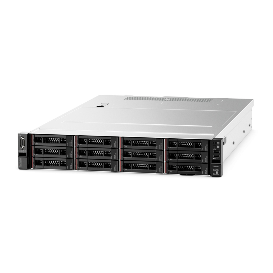
- Page 21 Figure 6. Front view of server models with eight 3.5-inch hot-swap drives (0-7) Figure 7. Front view of server models with twelve 3.5-inch hot-swap drives (0-11) Table 4. Components on the front of server models with 3.5-inch hot-swap drives Callout Callout Rack latch (left) 3.5-inch hot-swap drive bays...
- Page 22 19. Pull-out information tab The Lenovo XClarity Controller network access label of the server is attached on the pull-out information tab. VGA connector (optional) Used to attach a high-performance monitor, a direct-drive monitor, or other devices that use a VGA connector.
-
Page 23: Front I/O Assembly
19. Pull-out information tab The Lenovo XClarity Controller network access label of the server is attached on the pull-out information tab. VGA connector (optional) Used to attach a high-performance monitor, a direct-drive monitor, or other devices that use a VGA connector. - Page 24 • If the connector is set to have both functions, you can press the ID button for three seconds to switch between the two functions. For more information, see “Set the network connection for the Lenovo XClarity Controller” on page 91. USB 3.0 connector Attach a USB-compatible device, such as a keyboard, USB mouse, or USB storage device.
- Page 25 Each time you press the system ID button, the state of both the system ID LEDs changes. The LEDs can be changed to on, blinking, or off. You can also use the Lenovo XClarity Controller or a remote management program to change the state of the system ID LEDs to assist in visually locating the server among other servers.
-
Page 26: Rear View
PCIe slot 4 PCIe slot 5 PCIe slot 6 Power supply 2 (available on some models) Power supply 1 NMI button USB 3.0 connector USB 3.0 connector VGA connector Ethernet connector 2 (RJ-45) Ethernet connector 1 (RJ-45) ThinkSystem SR550 Setup Guide... - Page 27 • Your server supports PCIe slot 5 when two processors are installed. • PCIe slot 6 does not support PCIe adapters with external mini-SAS HD connectors. • Only use PCIe adapters provided by Lenovo. Lenovo makes no warranty regarding non-Lenovo products or services. For a list of supported PCIe adapters, see: http://www.lenovo.com/us/en/serverproven/...
-
Page 28: Rear View Leds
The hot-swap redundant power supplies help you avoid significant interruption to the operation of the system when a power supply fails. You can purchase a power supply option from Lenovo and install the power supply to provide power redundancy without turning off the server. On each power supply, there are three status LEDs near the power cord connector. - Page 29 Each time you press the system ID button, the state of both the system ID LEDs changes. The LEDs can be changed to on, blinking, or off. You can also use the Lenovo XClarity Controller or a remote management program to change the state of the system ID LEDs to assist in visually locating the server among other servers.
- Page 30 • Green: The server is on and the power supply is working normally. Power supply • Off: The power supply is working normally error LED • Yellow: The power supply has failed. To resolve the issue, replace the power supply. ThinkSystem SR550 Setup Guide...
-
Page 31: System Board Components
System board components The illustration in this section provides information about the components on the system board. Figure 13. System board components Callout Callout Riser 1 slot Serial-port-module connector LOM adapter connector /TPM connector (for Chinese Mainland only) Front USB connector Front VGA connector DIMM slots Processor 1 socket... -
Page 32: Internal Cable Routing
• Cable identifiers of some cables are printed on the cables that come with the server and optional devices. Use these identifiers to connect the cables to the correct connectors. • Ensure that the relevant cables pass through the cable clips. Figure 14. Cable clips ThinkSystem SR550 Setup Guide... - Page 33 Note: Disengage all latches, release tabs, or locks on cable connectors when you disconnect cables from the system board. Failing to release them before removing the cables will damage the cable sockets on the system board, which are fragile. Any damage to the cable sockets might require replacing the system board. Some options, such as RAID adapters, might require additional internal cabling.
-
Page 34: Server Models With Eight 3.5-Inch Simple-Swap Drives
Mini-SAS cable labeled with 1 SATA 4-7 connector on the system board Power cable labeled with 0 Backplane power connector 1 on the system board Power cable labeled with 1 Backplane power connector 2 on the system board ThinkSystem SR550 Setup Guide... -
Page 35: Server Models With Eight 3.5-Inch Hot-Swap
Server models with eight 3.5-inch hot-swap drives Use this section to understand the cable routing for server models with eight 3.5-inch hot-swap drives. Figure 16. Cable routing for server models with eight 3.5-inch hot-swap drives Cable From SAS signal cable SAS 0 and SAS 1 connectors on the C0 and C1 connectors on the RAID backplane... - Page 36 SAS 0 and SAS 1 connectors on the C0 and C1 connectors on the RAID backplane adapter installed in PCIe slot 1 Power cable Power connector on the backplane Backplane power connector 1 on the system board ThinkSystem SR550 Setup Guide...
-
Page 37: Drives
Server models with twelve 3.5-inch hot-swap drives Use this section to understand the cable routing for server models with twelve 3.5-inch hot-swap drives. Figure 18. Cable routing for server models with twelve 3.5-inch hot-swap drives and 16i adapter Cable From SAS signal cable SAS 0 and SAS 1 connectors on the C0 and C1 connectors on the RAID... - Page 38 PCIe slot 1 Power cable Power connector 1 on the backplane Backplane power connector 1 on the system board Power cable Power connector 2 on the backplane Backplane power connector 2 on the system board ThinkSystem SR550 Setup Guide...
-
Page 39: Server Models With Eight 2.5-Inch Hot-Swap
Server models with eight 2.5-inch hot-swap drives Use this section to understand the cable routing for server models with eight 2.5-inch hot-swap drives. Note: Both 8i and 16i RAID adapters are supported in this configuration. Figure 20. Cable routing for server models with eight 2.5-inch hot-swap drives From Cable SAS signal cable... - Page 40 SAS 0 and SAS 1 connectors on the C0 and C1 connectors on the RAID backplane adapter installed in PCIe slot 1 Power cable Power connector on the backplane Backplane power connector 1 on the system board ThinkSystem SR550 Setup Guide...
-
Page 41: Drives
Server models with sixteen 2.5-inch hot-swap drives Use this section to understand the cable routing for server models with sixteen 2.5-inch hot-swap drives. Figure 22. Cable routing for server models with sixteen 2.5-inch hot-swap drives and 8i adapters Cable From SAS signal cable SAS 0 and SAS 1 connectors on the C0 and C1 connectors on the RAID... - Page 42 PCIe slot 2 Power cable Power connector 1 on the backplane Backplane 1 power connector on the system board Power cable Power connector 2 on the backplane Backplane 2 power connector on the system board ThinkSystem SR550 Setup Guide...
- Page 43 Figure 24. Cable routing for server models with sixteen 2.5-inch hot-swap drives and 16i adapter From Cable SAS signal cable SAS 0 and SAS 1 connectors on the C0 and C1 connectors on the RAID backplane 1 adapter installed in PCIe slot 4 SAS signal cable SAS 0 and SAS 1 connectors on the C2 and C3 connectors on the RAID...
- Page 44 PCIe slot 1 Power cable Power connector 1 on the backplane Backplane power connector 1 on the system board Power cable Power connector 2 on the backplane Backplane power connector 2 on the system board ThinkSystem SR550 Setup Guide...
-
Page 45: Parts List
Use the parts list to identify each of the components that are available for your server. For more information about ordering the parts shown in Figure 26 “Server components” on page 41, go to: http://datacentersupport.lenovo.com/us/en/products/servers/thinksystem/sr550/7x03/parts Note: Depending on the model, your server might look slightly different from the following illustration. Some of the components might not be available on your server. - Page 46 Tier 1 CRU at your request with no service agreement, you will be charged for the installation. • Tier 2 customer replaceable unit (CRU): You may install a Tier 2 CRU yourself or request Lenovo to install it, at no additional charge, under the type of warranty service that is designated for your server.
- Page 47 Table 10. Parts list (continued) Index Description Tier 1 CRU Tier 2 Consuma- ble and Structural parts Front I/O assembly, server models with eight or √ sixteen 2.5-inch drive bays Front I/O assembly, server models with eight √ 3.5-inch drive bays System board √...
-
Page 48: Power Cords
The cord set should have the appropriate safety approvals for the country in which the equipment will be installed. • Power cords for a specific country or region are usually available only in that country or region. ThinkSystem SR550 Setup Guide... -
Page 49: Chapter 3. Server Hardware Setup
Validate that the server hardware was set up successfully. See “Validate server setup” on page 90. 3. Configure the system. a. Connect the Lenovo XClarity Controller to the management network. See “Set the network connection for the Lenovo XClarity Controller” on page 91. -
Page 50: Installation Guidelines
Go to to download firmware updates for your server. ThinkSystem SR550 Drivers and Software Important: Some cluster solutions require specific code levels or coordinated code updates. If the component is part of a cluster solution, verify that the latest level of code is supported for the cluster solution before you update the code. -
Page 51: Safety Inspection Checklist
Click the Power tab to see all line cords. • Make sure that the insulation is not frayed or worn. 3. Check for any obvious non-Lenovo alterations. Use good judgment as to the safety of any non-Lenovo alterations. 4. Check inside the server for any obvious unsafe conditions, such as metal filings, contamination, water or other liquid, or signs of fire or smoke damage. -
Page 52: System Reliability Guidelines
Attention: Prevent exposure to static electricity, which might lead to system halt and loss of data, by keeping static-sensitive components in their static-protective packages until installation, and handling these devices with an electrostatic-discharge wrist strap or other grounding system. ThinkSystem SR550 Setup Guide... -
Page 53: Install Server Hardware Options
• Always download and apply the latest firmware. This will help ensure that any known issues are addressed, and that your server is ready to work with optimal performance. Go to ThinkSystem SR550 to download firmware updates for your server. -
Page 54: Remove The Security Bezel
Use the key to unlock the security bezel to the open position. Figure 27. Unlocking the security bezel Step 2. Press the release latch and pivot the security bezel outward to remove it from the chassis. ThinkSystem SR550 Setup Guide... -
Page 55: Remove The Top Cover
Figure 28. Security bezel removal Attention: Before you ship the rack with the server installed, reinstall and lock the security bezel into place. Remove the top cover Use this information to remove the top cover. “Read the “Power off “ATTENTION: installation the server Static Sensitive Device... -
Page 56: Remove The Air Baffle
Ground package before opening” page 46 on page 90 on page 48 S033 CAUTION: Hazardous energy present. Voltages with hazardous energy might cause heating when shorted with metal, which might result in spattered metal, burns, or both. S017 ThinkSystem SR550 Setup Guide... -
Page 57: Install A Processor-Heat-Sink Module
CAUTION: Hazardous moving fan blades nearby. Keep fingers and other body parts away. If there is a RAID super capacitor module installed on the top of the air baffle, remove the RAID super capacitor module first. To remove the air baffle, complete the following step: Watch the procedure. - Page 58 Remove the processor socket cover, if one is installed on the processor socket, by placing your fingers in the half-circles at each end of the cover and lifting it from the system board. Step 2. Install the processor-heat-sink module on the system board. ThinkSystem SR550 Setup Guide...
-
Page 59: Install A Memory Module
Note: An Intel Xeon SP Gen 2 processor does not come with a system fan. If you are installing an Intel Xeon SP Gen 2 processor, ensure that you have ordered the ThinkSystem SR550 FAN Option Kit and install it. - Page 60 Then, take the new memory module out of the package. To install a memory module, complete the following steps: Watch the procedure. A video of the installation process is available: • YouTube: https://www.youtube.com/playlist?list=PLYV5R7hVcs-C9jFjZnXQ6AmTXaIdX6_HJ • Youku: http://list.youku.com/albumlist/show/id_50429987 ThinkSystem SR550 Setup Guide...
- Page 61 Figure 32. Memory module installation Step 1. Open the retaining clips on each end of the memory module slot. Attention: To avoid breaking the retaining clips or damaging the memory module slots, open and close the clips gently. Step 2. Align the memory module with the slot, and gently place the memory module on the slot with both hands.
- Page 62 The following illustration helps you to locate the memory module slots on the system board. Figure 33. Memory module slots on the system board The following memory configurations are available: • “Independent mode” on page 59 • “Mirroring mode” on page 60 • “Rank sparing mode” on page 61 ThinkSystem SR550 Setup Guide...
- Page 63 Note: If there are three identical memory modules to be installed for CPU1, and the three memory modules have the same Lenovo part number, install the three memory modules in slots 1, 2, and 3. Table 11. Independent mode with one processor...
- Page 64 The following table shows the memory module population sequence for mirroring mode when two processors (CPU1 and CPU2) are installed. Table 14. Mirroring mode with two processors Processor 2 Processor 2 Total Total memo- memory modules mod- ules ThinkSystem SR550 Setup Guide...
-
Page 65: Install The 2.5-Inch-Drive Backplane
Rank sparing mode In rank sparing mode, one rank of a memory module works as the spare rank for the other ranks on the same channel. The spare rank is not available as system memory. Notes: • All memory modules to be installed must be the same type with the same capacity, frequency, voltage, and number of ranks. - Page 66 Watch the procedure. A video of the installation process is available: • YouTube: https://www.youtube.com/playlist?list=PLYV5R7hVcs-C9jFjZnXQ6AmTXaIdX6_HJ • Youku: http://list.youku.com/albumlist/show/id_50429987 Step 1. Determine the location of the backplanes to be installed. Step 2. Connect the cables to the backplane. ThinkSystem SR550 Setup Guide...
- Page 67 Step 3. Insert the bottom of the backplane into the slots on the bottom of the chassis. Then, rotate the backplane to vertical position and align the holes in the backplane with the pins on the chassis and press the backplane into position. The release tabs will secure the backplane in place. Figure 34.
-
Page 68: Install The 3.5-Inch-Drive Backplane
Then, take the new backplane out of the package and place it on a static-protective surface. To install the 3.5-inch-drive backplane, complete the following steps: Watch the procedure. A video of the installation process is available: • YouTube: https://www.youtube.com/playlist?list=PLYV5R7hVcs-C9jFjZnXQ6AmTXaIdX6_HJ • Youku: http://list.youku.com/albumlist/show/id_50429987 ThinkSystem SR550 Setup Guide... - Page 69 Figure 36. 3.5-inch-drive backplane installation Step 1. Connect the cables to the backplane. Step 2. Align the backplane with the chassis and lower it into the chassis. Then, put the backplane into place with it leaning backward slightly. Step 3. Rotate the backplane to vertical position to ensure that the four hooks on the chassis pass through the corresponding holes in the backplane.
-
Page 70: Install A System Fan
Hazardous energy present. Voltages with hazardous energy might cause heating when shorted with metal, which might result in spattered metal, burns, or both. S009 CAUTION: To avoid personal injury, disconnect the fan cables before removing the fan from the device. ThinkSystem SR550 Setup Guide... - Page 71 S002 CAUTION: The power-control button on the device and the power switch on the power supply do not turn off the electrical current supplied to the device. The device also might have more than one power cord. To remove all electrical current from the device, ensure that all power cords are disconnected from the power source.
-
Page 72: Install The Serial Port Module
Connect the cable of the serial port module to serial-port-module connector on the system board. For the location of the serial-port-module connector, see “System board components” on page 27. After installing the serial port module, do one of the following to enable it according to the installed operating system: ThinkSystem SR550 Setup Guide... -
Page 73: Install The Lom Adapter
• For Linux operating system: Open the ipmitool and enter the following command to disable the Serial over LAN (SOL) feature: -I lanplus -H IP -U USERID -P PASSW0RD sol deactivate • For Microsoft Windows operating system: 1. Open the ipmitool and enter the following command to disable the SOL feature: -I lanplus -H IP -U USERID -P PASSW0RD sol deactivate 2. -
Page 74: Install A Pcie Adapter
PCIe adapters are supported. Lenovo makes no warranty regarding non- ® Lenovo products or services. Support for non-Lenovo ServerProven® PCIe adapters is provided by non- Lenovo manufacturers. • When installing Ethernet adapters with RJ-45 connector, observe the following installation sequence: Table 17. - Page 75 “Read the “Power off “ATTENTION: installation the server Static Sensitive Device Guidelines” on for this task” Ground package before opening” page 46 on page 90 on page 48 Before you install a PCIe adapter on the riser assembly, touch the static-protective package that contains the new PCIe adapter to any unpainted surface on the outside of the server.
- Page 76 Figure 41. Installing a PCIe adapter on the riser assembly Note: Carefully handle the PCIe adapter by its edges. Step 5. Pivot the retention latch to the closed position to secure the PCIe adapter in position. ThinkSystem SR550 Setup Guide...
- Page 77 Figure 42. Pivoting the retention latch to the closed position Step 6. Depending on the type of the PCIe adapter, you might need to connect any required cables. Refer to the documentation that comes with the PCIe adapter for specific information. Install a PCIe adapter on the system board Use this information to install a PCIe adapter on the system board.
-
Page 78: Install The M.2 Backplane And M.2 Drive
2. Adjust the retainer on the M.2 backplane to accommodate the particular size of the M.2 drive you wish to install. See “Adjust the retainer on the M.2 backplane” on page 77. 3. Locate the connector on each side of the M.2 backplane. Notes: ThinkSystem SR550 Setup Guide... - Page 79 • Some M.2 backplanes support two identical M.2 drives. When two M.2 drives are installed, align and support both M.2 drives when sliding the retainer forward to secure the M.2 drives. • Install the M.2 drive in slot 0 first. Slot 0 Slot 1 Figure 44.
- Page 80 Then, insert the M.2 backplane into the M.2 slot on the system board and press it down to fully seat it. Figure 46. M.2 backplane installation For server models with twelve 3.5-inch hot-swap drives, if you are installing the 480 GB M.2 drive, install the M.2 drive air baffle for proper airflow. ThinkSystem SR550 Setup Guide...
- Page 81 Figure 47. M.2 drive air baffle installation After installing the M.2 drive, M.2 backplane and the air baffle, use the Lenovo XClarity Provisioning Manager to configure the RAID. For more information, see: http://sysmgt.lenovofiles.com/help/topic/LXPM/RAID_setup.html Adjust the retainer on the M.2 backplane Use this information to adjust the retainer on the M.2 backplane.
-
Page 82: Install A Hot-Swap Power Supply
• If you are replacing the existing power supply with a new power supply of different wattage, attach the power information label that comes with this option onto the existing label on the top cover near the power supply. ThinkSystem SR550 Setup Guide... - Page 83 Figure 49. Hot-swap power supply label on the cover S035 CAUTION: Never remove the cover on a power supply or any part that has this label attached. Hazardous voltage, current, and energy levels are present inside any component that has this label attached. There are no serviceable parts inside these components.
- Page 84 To install a hot-swap power supply, complete the following steps: Watch the procedure. A video of the installation process is available: • YouTube: https://www.youtube.com/playlist?list=PLYV5R7hVcs-C9jFjZnXQ6AmTXaIdX6_HJ • Youku: http://list.youku.com/albumlist/show/id_50429987 ThinkSystem SR550 Setup Guide...
-
Page 85: Install The Air Baffle
Step 1. Touch the static-protective package that contains the new power supply to any unpainted surface on the outside of the server. Then, take the power supply out of the package and place it on a static-protective surface. Step 2. If there is a power supply filler installed, remove it. - Page 86 Step 1. Align the air baffle tabs with the slots on both sides of the chassis; then, lower the air baffle into the server. Step 2. Press the air baffle down until it is securely seated. ThinkSystem SR550 Setup Guide...
-
Page 87: Install A Raid Super Capacitor Module
Note: Close the retaining clip on each end of the DIMM slot before installing the air baffle for proper cooling. Step 3. Install any RAID super capacitor module that you have removed. After installing the air baffle, install the top cover. See “Install the top cover” on page 84. Install a RAID super capacitor module Use this information to install a RAID super capacitor module. -
Page 88: Install The Top Cover
2. Ensure that all internal cables are correctly routed. See “Internal cable routing” on page 28. To install the top cover, complete the following steps: Watch the procedure. A video of the installation process is available: • YouTube: https://www.youtube.com/playlist?list=PLYV5R7hVcs-C9jFjZnXQ6AmTXaIdX6_HJ ThinkSystem SR550 Setup Guide... -
Page 89: Install A Hot-Swap Drive
Notes: • For a list of supported drives, see http://www.lenovo.com/us/en/serverproven/ • The drive bays are numbered to indicate the installation order (starting from number “0”). Follow the installation order when you install a drive. See “Front view” on page 15. - Page 90 Figure 56. 2.5-inch drive filler removal Figure 57. 3.5-inch drive filler removal 2. Touch the static-protective package that contains the new drive to any unpainted surface on the outside of the server. Then, take the new drive out of the package. ThinkSystem SR550 Setup Guide...
-
Page 91: Install A Simple-Swap Drive
To install a hot-swap drive, complete the following steps: Watch the procedure. A video of the installation process is available: • YouTube: https://www.youtube.com/playlist?list=PLYV5R7hVcs-C9jFjZnXQ6AmTXaIdX6_HJ • Youku: http://list.youku.com/albumlist/show/id_50429987 Figure 58. 2.5-inch hot-swap drive installation Figure 59. 3.5-inch hot-swap drive installation Step 1. Ensure that the drive handle is in the open position. - Page 92 2. Touch the static-protective package that contains the new drive to any unpainted surface on the outside of the server. Then, take the new drive out of the package. To install a simple-swap drive, complete the following steps: ThinkSystem SR550 Setup Guide...
-
Page 93: Install The Server In A Rack
Figure 61. Simple-swap drive installation Step 1. Ensure that the drive handle is in the open position. Slide the drive into the drive bay until it snaps into position. Step 2. Rotate the tray handle to the closed position. Install the server in a rack To install the server in a rack, follow the instructions that are provided in the Rail Installation Kit for the rails on which the server will be installed. -
Page 94: Validate Server Setup
Power off the server The server remains in a standby state when it is connected to a power source, allowing the Lenovo XClarity Controller to respond to remote power-on requests. To remove all power from the server (power status LED off), you must disconnect all power cables. -
Page 95: Chapter 4. System Configuration
The following methods are available to set the network connection for the Lenovo XClarity Controller if you are not using DHCP: • If a monitor is attached to the server, you can use Lenovo XClarity Controller to set the network connection. -
Page 96: Update The Firmware
Machine-type-specific firmware-only UXSPs are also available. See the following table to determine the best Lenovo tool to use for installing and setting up the firmware: Note: The server UEFI settings for option ROM must be set to Auto or UEFI to update firmware using Lenovo XClarity Administrator or Lenovo XClarity Essentials. - Page 97 Supports update update update update Tool interface line interface UXSPs √ √ √ √ Lenovo XClarity Provisioning Manager Limited to core system firmware only. √ √ √ √ Lenovo XClarity Controller Supports core system firmware and most advanced I/O option firmware updates √...
- Page 98 Additional information about using Lenovo XClarity Provisioning Manager to update firmware is available http://sysmgt.lenovofiles.com/help/topic/LXPM/platform_update.html • Lenovo XClarity Controller If you need to install a specific update, you can use the Lenovo XClarity Controller interface for a specific server. Notes: – To perform an in-band update through Windows or Linux, the operating system driver must be installed and the Ethernet-over-USB (sometimes called LAN over USB) interface must be enabled.
-
Page 99: Configure The Firmware
Several options are available to install and set up the firmware for the server. Important: Do not configure option ROMs to be set to Legacy unless directed to do so by Lenovo Support. This setting prevents UEFI drivers for the slot devices from loading, which can cause negative side effects for Lenovo software, such as Lenovo XClarity Administrator and Lenovo XClarity Essentials OneCLI, and to the Lenovo XClarity Controller. -
Page 100: Memory Configuration
OS logical drives or volumes. An introduction to RAID is available at the following Lenovo Press website: https://lenovopress.com/lp0578-lenovo-raid-introduction Detailed information about RAID management tools and resources is available at the following Lenovo Press website: https://lenovopress.com/lp0579-lenovo-raid-management-tools-and-resources Deploy the operating system Several options are available to deploy an operating system on the server. -
Page 101: Back Up The Server Configuration
Alternatively, you can use the s s a a v v e e command from Lenovo XClarity Essentials OneCLI to create a backup of all configuration settings. For more information about the s s a a v v e e command, see: http://sysmgt.lenovofiles.com/help/topic/toolsctr_cli_lenovo/onecli_r_save_command.html... - Page 102 • From Lenovo XClarity Provisioning Manager V3 To update the UUID from Lenovo XClarity Provisioning Manager V3: 1. Start the server and press F1 to display the Lenovo XClarity Provisioning Manager V3 interface. 2. If the power-on Administrator password is required, enter the password.
-
Page 103: Update The Asset Tag
4. Update the asset tag information. • From Lenovo XClarity Essentials OneCLI Lenovo XClarity Essentials OneCLI sets the asset tag in the Lenovo XClarity Controller. Select one of the following methods to access the Lenovo XClarity Controller and set the asset tag: –... - Page 104 If you do not specify any of these parameters, OneCLI will use the default values. When the default values are used and OneCLI is unable to access the Lenovo XClarity Controller using the online authenticated LAN access method, OneCLI will automatically use the unauthenticated KCS access method.
- Page 105 Note: BMC, IMM, or XCC internal LAN/USB IP address, account name, and password are all valid for this command. Example that uses the user ID and password default values: onecli config set SYSTEM_PROD_DATA.SysEncloseAssetTag <asset_tag> --host <xcc_ip> 4. Reset the Lenovo XClarity Controller to the factory defaults. Go to https://sysmgt.lenovofiles.com/help/ for more information. topic/com.lenovo.systems.management.xcc.doc/NN1ia_c_resettingthexcc.html...
- Page 106 ThinkSystem SR550 Setup Guide...
-
Page 107: Chapter 5. Resolving Installation Issues
• “Displayed system memory less than installed physical memory” on page 105 • “A Lenovo optional device that was just installed does not work.” on page 105 • “Voltage planar fault is displayed in the event log” on page 105... - Page 108 • Replace the affected backplane signal cable. • Replace the affected backplane. 8. Run the diagnostics tests for the hard disk drives. When you start a server and press F1, the Lenovo XClarity Provisioning Manager interface is displayed by default. You can perform hard drive diagnostics from this interface.
- Page 109 • There is no memory mismatch when the server is at the minimum memory configuration. 2. Reseat the DIMMs, and then restart the server. 3. Run memory diagnostics. When you start a server and press F1, the Lenovo XClarity Provisioning Manager interface is displayed by default. You can perform memory diagnostics from this interface.
- Page 110 • If the system restarts, add each of the items that you removed one at a time, restarting the system each time, until the error occurs. Replace the item for which the error occurs. • If the system does not restart, suspect the system board. ThinkSystem SR550 Setup Guide...
-
Page 111: Appendix A. Getting Help And Technical Assistance
Gathering information needed to call Support If you believe that you require warranty service for your Lenovo product, the service technicians will be able to assist you more efficiently if you prepare before you call. You can also see http:// for more information about your product warranty. -
Page 112: Collecting Service Data
Collecting service data To clearly identify the root cause of a server issue or at the request of Lenovo Support, you might need collect service data that can be used for further analysis. Service data includes information such as event logs and hardware inventory. -
Page 113: Contacting Support
Contacting Support You can contact Support to obtain help for your issue. You can receive hardware service through a Lenovo Authorized Service Provider. To locate a service provider authorized by Lenovo to provide warranty service, go to https://datacentersupport.lenovo.com/ and use filter searching for different countries. For Lenovo support telephone numbers, see serviceprovider for your region support details. - Page 114 ThinkSystem SR550 Setup Guide...
-
Page 115: Appendix B. Trademarks
Intel, Optane, and Xeon are trademarks of Intel Corporation in the United States, other countries, or both. Microsoft and Windows are trademarks of the Microsoft group of companies. Linux is a registered trademark of Linus Torvalds. All other trademarks are the property of their respective owners. © 2020 Lenovo. © Copyright Lenovo 2017, 2020... - Page 116 ThinkSystem SR550 Setup Guide...
-
Page 117: Index
PCIe adapter collecting service data PCIe adapter on the riser assembly Common installation issues PCIe adapter on the system board Configuration - ThinkSystem SR550 simple-swap drive configure the firmware top cover contamination, particulate and gaseous internal cable routing... - Page 118 PCIe adapter support web page, custom installing system board components PCIe adapter on the riser assembly System configuration - ThinkSystem SR550 installing system reliability guidelines PCIe adapter on the system board installing option install power cords power off the server...