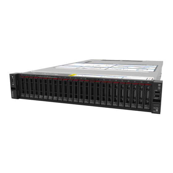
Lenovo ThinkSystem SR650 Maintenance Manual
2u rack server
Hide thumbs
Also See for ThinkSystem SR650:
- Setup manual (226 pages) ,
- Product manual (87 pages) ,
- Quick start manual (14 pages)
Table of Contents
Advertisement
Quick Links
Advertisement
Table of Contents

Related Manuals for Lenovo ThinkSystem SR650


Summary of Contents for Lenovo ThinkSystem SR650
- Page 1 ThinkSystem SR650 Maintenance Manual Machine Types: 7X05 and 7X06...
- Page 2 Before using this information and the product it supports, be sure to read and understand the safety information and the safety instructions, which are available at: http://thinksystem.lenovofiles.com/help/topic/safety_documentation/pdf_files.html In addition, ensure that you are familiar with the terms and conditions of the Lenovo warranty for your server, which can be found at: http://datacentersupport.lenovo.com/warrantylookup Second Edition (November 2017) ©...
-
Page 3: Table Of Contents
LOM adapter replacement ..162 RAID super capacitor module replacement ..106 Remove the LOM adapter ..162 © Copyright Lenovo 2017... - Page 4 General problem determination procedures ..207 Index ....231 Resolving suspected power problems ..207 ThinkSystem SR650 Maintenance Manual...
-
Page 5: Safety
Vor der Installation dieses Produkts die Sicherheitshinweise lesen. Prima di installare questo prodotto, leggere le Informazioni sulla Sicurezza. Les sikkerhetsinformasjonen (Safety Information) før du installerer dette produktet. Antes de instalar este produto, leia as Informações sobre Segurança. © Copyright Lenovo 2017... -
Page 6: Safety Inspection Checklist
This equipment must be installed by trained service personnel, as defined by the NEC and IEC 60950- 1, Second Edition, the standard for Safety of Information Technology Equipment. Lenovo assumes you are qualified in the servicing of equipment and trained in recognizing hazards in products with hazardous energy levels. - Page 7 3. Check for any obvious non-Lenovo alterations. Use good judgment as to the safety of any non-Lenovo alterations. 4. Check inside the server for any obvious unsafe conditions, such as metal filings, contamination, water or other liquid, or signs of fire or smoke damage.
- Page 8 ThinkSystem SR650 Maintenance Manual...
-
Page 9: Chapter 1. Introduction
Chapter 1. Introduction The ThinkSystem SR650 server is a 2U rack server designed for performance and expansion for various IT workloads. With the modular design, the server is flexible to be customized for maximum storage capacity or high storage density with selectable input/output options and tiered system management. - Page 10 Scan the QR code with a mobile device and a QR code reader application to get quick access to the Lenovo Service web site for this server. The Lenovo Service Information Web site provides additional information for parts installation and replacement videos, and error codes for server support.
-
Page 11: Specifications
• Scalable up to 28 cores • Thermal Design Power (TDP): up to 205 watts For a list of supported processors, see: http://www.lenovo.com/us/en/serverproven/ Note: If you want to install the following processors to the server, ensure that the server chassis is twenty-four 2.5-inch-bay chassis and one backplane is installed in only the middle cage (for drive bays 8–15). - Page 12 – One VGA connector – One XClarity Controller network connector – One serial port (available on some models) – Two USB 3.0 connectors – Two or four Ethernet connectors on the LOM adapter (available on some models) ThinkSystem SR650 Maintenance Manual...
- Page 13 Table 1. Server specifications (continued) Specification Description Graphics processing unit • Full-height, full-length, double-width (GPU) • TDP: up to 300 watts Note: GPU is supported only when the following hardware configuration requirements are met at the same time: • Server model: eight 3.5-inch-drive bays, eight 2.5-inch-drive bays, or sixteen 2.5- inch-drive bays •...
- Page 14 ASHRAE class A3 and class A4 specifications. To comply with ASHRAE class A3 and class A4 specifications, the server models must meet the following hardware configuration requirements at the same time: • Two power supplies installed ThinkSystem SR650 Maintenance Manual...
-
Page 15: Firmware Updates
Hat Enterprise Linux (RHEL) and SUSE Linux Enterprise Server (SLES) operating system distributions. Machine-type-specific firmware-only UXSPs are also available. See the following table to determine the best Lenovo tool to use for installing and setting up the firmware: Chapter 1... - Page 16 The latest firmware can be found at the following site: http://datacentersupport.lenovo.com/products/servers/thinksystem/sr650/7X05/downloads • Lenovo XClarity Provisioning Manager From Lenovo XClarity Provisioning Manager, you can update the Lenovo XClarity Controller firmware, the UEFI firmware, and the Lenovo XClarity Provisioning Manager software. ThinkSystem SR650 Maintenance Manual...
- Page 17 Additional information about using Lenovo XClarity Provisioning Manager to update firmware is available http://sysmgt.lenovofiles.com/help/topic/LXPM/platform_update.html • Lenovo XClarity Controller If you need to install a specific update, you can use the Lenovo XClarity Controller interface for a specific server. Notes: – To perform an in-band update through Windows or Linux, the operating system driver must be installed and the Ethernet-over-USB (sometimes called LAN over USB) interface must be enabled.
-
Page 18: Configuring The Lan Over Usb Interface Manually
Return to the Device Manager. Lenovo USB Remote NDIS Network Device appears under Network Adapters. Step 9. Use the Lenovo XClarity Controller interface to view or set the IP address for the LAN adapter. Additional information about using the Lenovo XClarity Controller to configure LAN over USB is available at: http://sysmgt.lenovofiles.com/help/topic/com.lenovo.systems.management.xcc.doc/NN1ia_c_... -
Page 19: Tech Tips
Power off the server The server remains in a standby state when it is connected to a power source, allowing the Lenovo XClarity Controller to respond to remote power-on requests. To remove all power from the server (power status LED off), you must disconnect all power cables. - Page 20 ThinkSystem SR650 Maintenance Manual...
-
Page 21: Chapter 2. Server Components
• The chassis for sixteen 2.5-inch-drive bays cannot be upgraded to the chassis for twenty-four 2.5-inch- drive bays. Figure 5. Front view of server models with eight 2.5-inch drive bays Figure 6. Front view of server models with sixteen 2.5-inch drive bays © Copyright Lenovo 2017... - Page 22 Table 2. Components on the front of server models with 2.5-inch drives Callout Callout Pull-out information tab Front I/O assembly Drive bays Rack latch (right) Rack latch (left) VGA connector (available on some models) Drive activity LED Drive status LED Drive bay filler Pull-out information tab ThinkSystem SR650 Maintenance Manual...
-
Page 23: Front I/O Assembly
The XClarity Controller network access label is attached on the top side of the pull-out information tab. Front I/O assembly For information about the controls, connectors, and status LEDs on the front I/O assembly, see “Front I/O assembly” on page 15. Rack latches If your server is installed in a rack, you can use the rack latches to help you slide the server out of the rack. - Page 24 • If the connector is set to have both functions, you can press the system ID button for three seconds to switch between the two functions. USB 3.0 connector Used to attach a device that requires a USB 2.0 or 3.0 connection, such as a keyboard, a mouse, or a USB storage device. ThinkSystem SR650 Maintenance Manual...
- Page 25 Each time you press the system ID button, the state of both the system ID LEDs changes. The LEDs can be changed to on, blinking, or off. You can also use the Lenovo XClarity Controller or a remote management program to change the state of the system ID LEDs to assist in visually locating the server among other servers.
-
Page 26: Rear View
Table 4. Components on the rear of the server Callout Callout Ethernet connectors on the LOM adapter (available on XClarity Controller network connector some models) VGA connector USB 3.0 connectors (2) NMI button Power supply 1 ThinkSystem SR650 Maintenance Manual... - Page 27 The hot-swap redundant power supplies help you avoid significant interruption to the operation of the system when a power supply fails. You can purchase a power supply option from Lenovo and install the power supply to provide power redundancy without turning off the server.
- Page 28 The number of the installed drives in your server varies by model. The EMI integrity and cooling of the server are protected by having all drive bays occupied. The vacant drive bays must be occupied by drive bay fillers or drive fillers. ThinkSystem SR650 Maintenance Manual...
-
Page 29: Rear View Leds
Each time you press the system ID button, the state of both the system ID LEDs changes. The LEDs can be changed to on, blinking, or off. You can also use the Lenovo XClarity Controller or a remote management program to change the state of the system ID LEDs to assist in visually locating the server among other servers. - Page 30 LED is off, replace the power supply. Power supply error LED • Yellow: The power supply has failed. To resolve the issue, replace the power supply. • Off: The power supply is working normally. ThinkSystem SR650 Maintenance Manual...
-
Page 31: System Board Components
System board components The illustration in this section shows the component locations on the system board. Figure 15. System board components Table 6. Components on the system board Callout Callout Riser 2 slot Serial-port-module connector PCIe slot 4 RAID adapter slot Riser 1 slot BIOS ROM programming connector LOM adapter connector... -
Page 32: System Board Leds
System ID LED System error LED DIMM error LEDs (24) Fan 1 error LED Fan 2 error LED Fan 3 error LED Fan 4 error LED Fan 5 error LED Fan 6 error LED System power LED ThinkSystem SR650 Maintenance Manual... - Page 33 Each time you press the system ID button, the state of both the system ID LEDs changes. The LEDs can be changed to on, blinking, or off. You can also use the Lenovo XClarity Controller or a remote management program to change the state of the system ID LEDs to assist in visually locating the server among other servers.
-
Page 34: System Board Jumpers
Cryptography Module (for China only) Force XCC update jumper • Pins 1 and 2: The jumper is in default setting. • Pins 2 and 3: Force the Lenovo XClarity Controller o update to the latest version. Force XCC reset jumper J181 •... -
Page 35: Internal Cable Routing
• Before you move any jumpers, power off the server; then, disconnect all power cords and external cables. Do not open your server or attempt any repair before reading and understanding the following information: – http://thinksystem.lenovofiles.com/help/topic/safety_documentation/pdf_files.html – “Handling static-sensitive devices” on page 91 •... -
Page 36: Vga Connector
Use the section to understand the cable routing for the VGA connector on the left rack latch. Note: The VGA connector is available on some models. Figure 18. VGA connector cable routing From VGA cable on the left rack latch Front VGA connector on the system board ThinkSystem SR650 Maintenance Manual... -
Page 37: Front I/O Assembly
Front I/O assembly Use the section to understand the cable routing for the front I/O assembly. Front I/O assembly on the chassis Figure 19. Cable routing for the front I/O assembly on the chassis From Operator-information-panel cable Operator-information-panel connector on the system board Front USB cable Front USB connector on the system board... - Page 38 Front I/O assembly on the right rack latch Figure 20. Cable routing for the front I/O assembly on the right rack latch From Front-I/O-assembly cable Operator-information-panel connector and front USB connector on the system board ThinkSystem SR650 Maintenance Manual...
-
Page 39: Gpu
Use the section to understand the cable routing for the GPUs. Figure 21. GPU cable routing Cable From GPU power cable Power connector on the GPU GPU power connector 1 on the system board GPU power cable Power connector on the GPU GPU power connector 2 on the system board Chapter 2... -
Page 40: Backplane
• The PCIe slot 7 refers to the RAID adapter slot on the system board. • If the rear hot-swap drive assembly is installed, PCIe slots 1, 2, and 3 will become unavailable because the space is occupied by the rear hot-swap drive assembly. ThinkSystem SR650 Maintenance Manual... - Page 41 Server models with eight 2.5-inch drives Use this section to understand the cable routing for server models with eight 2.5-inch drives. Server model: eight 2.5-inch SAS/SATA drives, the rear hot-swap drive assembly, one 16i RAID adapter Figure 22. Cable routing for server models with eight 2.5-inch SAS/SATA drives, the rear hot-swap drive assembly, and one 16i RAID adapter Cable From...
- Page 42 RAID adapter slot SAS signal cable for the rear hot- Signal connector on the rear hot- C0 connector on the 8i RAID adapter swap drive assembly swap drive assembly installed on PCIe slot 4 ThinkSystem SR650 Maintenance Manual...
- Page 43 Server model: four 2.5-inch SAS/SATA drives, four 2.5-inch NVMe drives, the rear hot-swap drive assembly, two 8i RAID adapters Note: The cable routing illustration is based on the scenario that the rear hot-swap drive assembly is installed. Depending on the model, the rear hot-swap drive assembly and the 8i RAID adapter on PCIe slot 4 might not be available on your server.
- Page 44 SAS signal cable for the rear hot- Signal connector on the rear hot- C0 connector on the 8i RAID adapter swap drive assembly swap drive assembly installed on PCIe slot 4 ThinkSystem SR650 Maintenance Manual...
- Page 45 Server model: four 2.5-inch SAS/SATA drives, four 2.5-inch NVMe drives, the rear hot-swap drive assembly, one 16i RAID adapter Figure 25. Cable routing for server models with four 2.5-inch SAS/SATA drives, four 2.5-inch NVMe drives, the rear hot- swap drive assembly, and one 16i RAID adapter Cable From Power cable for front backplane...
- Page 46 Backplane power connector 1 on the system board SAS signal cable for front SAS 0 and SAS 1 connectors on front C0 and C1 connectors on the 16i backplane 1 backplane 1 RAID adapter installed on the RAID adapter slot ThinkSystem SR650 Maintenance Manual...
- Page 47 Cable From SAS signal cable for front SAS 0 and SAS 1 connectors on front C2 and C3 connectors on the 16i backplane 2 backplane 2 RAID adapter installed on the RAID adapter slot Power cable for front backplane 2 Power connector on front backplane Backplane power connector 2 on the system board...
- Page 48 Backplane power connector 2 on the system board SAS signal cable for the rear hot- Signal connector on the rear hot- C2 connector on the 16i RAID swap drive assembly swap drive assembly adapter installed on PCIe slot 4 ThinkSystem SR650 Maintenance Manual...
- Page 49 Server model: sixteen 2.5-inch SAS/SATA drives, the rear hot-swap drive assembly, one 24i RAID adapter Figure 28. Cable routing for server models with sixteen 2.5-inch SAS/SATA drives, the rear hot-swap drive assembly, and one 24i RAID adapter Cable From Power cable for front backplane 1 Power connector on front backplane Backplane power connector 1 on the system board...
- Page 50 RAID adapter slot SAS signal cable for front SAS 0 and SAS 1 connectors on front C0 and C1 connectors on the 8i RAID backplane 2 backplane 2 adapter installed on PCIe slot 4 ThinkSystem SR650 Maintenance Manual...
- Page 51 Cable From Power cable for front backplane 2 Power connector on front backplane Backplane power connector 2 on the system board SAS signal cable for the rear hot- Signal connector on the rear hot- C0 connector on the 8i RAID adapter swap drive assembly swap drive assembly installed on PCIe slot 5...
- Page 52 C2 and C3 connectors on the 16i backplane 2 backplane 2 RAID adapter installed on the RAID adapter slot Power cable for front backplane 2 Power connector on front backplane Backplane power connector 2 on the system board ThinkSystem SR650 Maintenance Manual...
- Page 53 Server model: twelve 2.5-inch SAS/SATA drives, four 2.5-inch NVMe drives, the rear hot-swap drive assembly, one 8i RAID adapter, one 16i RAID adapter Figure 31. Cable routing for server models with twelve 2.5-inch SAS/SATA drives, four 2.5-inch NVMe drives, the rear hot-swap drive assembly, one 8i RAID adapter, and one 16i RAID adapter Cable From...
- Page 54 Backplane power connector 2 on the system board SAS signal cable for the rear hot- Signal connector on the rear hot- C4 connector on the 24i RAID swap drive assembly swap drive assembly adapter installed on PCIe slot 5 ThinkSystem SR650 Maintenance Manual...
- Page 55 Server model: eight 2.5-inch SAS/SATA drives, eight 2.5-inch NVMe drives, one 16i RAID adapter, one NVMe switch adapter Note: The cable routing illustration is based on the scenario that the NVMe switch adapter is installed on PCIe slot 1. If the NVMe switch adapter is installed on PCIe slot 5 or PCIe slot 6, route the NVMe signal cable for front backplane 2 along the left side of the chassis.
- Page 56 NVMe signal cable for front NVMe 0, NVMe 1, NVMe 2, and C0, C1, C2, and C3 connectors on backplane 2 NVMe 3 connectors on front the NVMe switch adapter installed on backplane 2 PCIe slot 1 ThinkSystem SR650 Maintenance Manual...
- Page 57 Server model: eight 2.5-inch SAS/SATA drives, eight 2.5-inch NVMe drives, the rear hot-swap drive assembly, one 8i RAID adapter, one 16i RAID adapter, one NVMe switch adapter Figure 34. Cable routing for server models with eight 2.5-inch SAS/SATA drives, eight 2.5-inch NVMe drives, the rear hot- swap drive assembly, one 8i RAID adapter, one 16i RAID adapter, and one NVMe switch adapter From Cable...
- Page 58 NVMe signal cable for front NVMe 0, NVMe 1, NVMe 2, and C0, C1, C2, and C3 connectors on backplane 2 NVMe 3 connectors on front the NVMe switch adapter installed on backplane 2 PCIe slot 5 ThinkSystem SR650 Maintenance Manual...
- Page 59 Cable From SAS signal cable for front SAS 0 and SAS 1 connectors on front C0 and C1 connectors on the 8i RAID backplane 2 backplane 2 adapter installed on PCIe slot 4 Backplane power connector 2 on the Power cable for front backplane 2 Power connector on front backplane system board SAS signal cable for the rear hot-...
- Page 60 Backplane power connector 2 on the system board SAS signal cable for the rear hot- Signal connector on the rear hot- C4 connector on the 24i RAID swap drive assembly swap drive assembly adapter installed on PCIe slot 6 ThinkSystem SR650 Maintenance Manual...
- Page 61 Server models with twenty-four 2.5-inch drives Use this section to understand the cable routing for server models with twenty-four 2.5-inch drives. Server model: twenty-four 2.5-inch SAS/SATA drives, one 8i RAID adapter, one 16i RAID adapter Figure 37. Cable routing for server models with twenty-four 2.5-inch SAS/SATA drives, one 8i RAID adapter, and one 16i RAID adapter Cable From...
- Page 62 Backplane power connector 2 on the system board SAS signal cable for front SAS 0 and SAS 1 connectors on front C2 and C3 connectors on the 24i backplane 2 backplane 2 RAID adapter installed on riser 1 assembly ThinkSystem SR650 Maintenance Manual...
- Page 63 Cable From Power cable for front backplane 3 Power connector on front backplane Backplane power connector 3 on the system board SAS signal cable for front SAS 0 and SAS 1 connectors on front C4 and C5 connectors on the 24i backplane 3 backplane 3 RAID adapter installed on riser 1...
- Page 64 Power cable for front backplane 2 Power connector on front backplane Backplane power connector 2 on the system board Power cable for front backplane 3 Power connector on front backplane Backplane power connector 3 on the system board ThinkSystem SR650 Maintenance Manual...
- Page 65 Cable From SAS signal cable for front SAS 0 and SAS 1 connectors on front C0 and C1 connectors on the 8i RAID backplane 3 backplane 3 adapter installed on PCIe slot 5 SAS signal cable for the rear hot- Signal connector on the rear hot- C0 connector on the 8i RAID adapter swap drive assembly...
- Page 66 RAID adapter installed on PCIe slot 5 SAS signal cable for the rear hot- Signal connector on the rear hot- C2 connector on the 16i RAID swap drive assembly swap drive assembly adapter installed on PCIe slot 5 ThinkSystem SR650 Maintenance Manual...
- Page 67 Server model: twenty-four 2.5-inch SAS/SATA drives, the rear hot-swap drive assembly, one 8i RAID adapter, one 24i RAID adapter Figure 41. Cable routing for server models with twenty-four 2.5-inch SAS/SATA drives, the rear hot-swap drive assembly, one 8i RAID adapter, and one 24i RAID adapter Cable From Backplane power connector 1 on the...
- Page 68 RAID adapter installed on PCIe slot 5 SAS signal cable for the rear hot- Signal connector on the rear hot- C4 connector on the 24i RAID swap drive assembly swap drive assembly adapter installed on PCIe slot 5 ThinkSystem SR650 Maintenance Manual...
- Page 69 Server model: twenty-four 2.5-inch SAS/SATA drives, the rear hot-swap drive assembly, two 16i RAID adapters Figure 42. Cable routing for server models with twenty-four 2.5-inch SAS/SATA drives, the rear hot-swap drive assembly, and two 16i RAID adapters Cable From Power cable for front backplane 1 Power connector on front backplane Backplane power connector 1 on the system board...
- Page 70 Backplane power connector 3 on the system board SAS signal cable for front SAS 0 and SAS 1 connectors on front C2 and C3 connectors on the 16i backplane 3 backplane 3 RAID adapter installed on PCIe slot 4 ThinkSystem SR650 Maintenance Manual...
- Page 71 Server model: twenty 2.5-inch SAS/SATA drives, four 2.5-inch NVMe drives, one 24i RAID adapter Figure 44. Cable routing for server models with twenty 2.5-inch SAS/SATA drives, four 2.5-inch NVMe drives, and one 24i RAID adapter From Cable Power cable for front backplane 1 Power connector on front backplane Backplane power connector 1 on the system board...
- Page 72 Power cable for front backplane 2 Power connector on front backplane Backplane power connector 2 on the system board Power cable for front backplane 3 Power connector on front backplane Backplane power connector 3 on the system board ThinkSystem SR650 Maintenance Manual...
- Page 73 Cable From SAS signal cable for front SAS 0 and SAS 1 connectors on front C0 and C1 connectors on the 8i RAID backplane 3 backplane 3 adapter installed on PCIe slot 5 SAS signal cable for the rear hot- Signal connector on the rear hot- C0 connector on the 8i RAID adapter swap drive assembly...
- Page 74 Power cable for front backplane 2 Power connector on front backplane Backplane power connector 2 on the system board Power cable for front backplane 3 Power connector on front backplane Backplane power connector 3 on the system board ThinkSystem SR650 Maintenance Manual...
- Page 75 Cable From SAS signal cable for front SAS 0 and SAS 1 connectors on front C0 and C1 connectors on the 16i backplane 3 backplane 3 RAID adapter installed on PCIe slot 5 SAS signal cable for the rear hot- Signal connector on the rear hot- C2 connector on the 16i RAID swap drive assembly...
- Page 76 Power cable for front backplane 2 Power connector on front backplane Backplane power connector 2 on the system board Power cable for front backplane 3 Power connector on front backplane Backplane power connector 3 on the system board ThinkSystem SR650 Maintenance Manual...
- Page 77 Cable From SAS signal cable for front SAS 0 and SAS 1 connectors on front C2 and C3 connectors on the 24i backplane 3 backplane 3 RAID adapter installed on PCIe slot 5 SAS signal cable for the rear hot- Signal connector on the rear hot- C4 connector on the 24i RAID swap drive assembly...
- Page 78 Power cable for front backplane 2 Power connector on front backplane Backplane power connector 2 on the system board Power cable for front backplane 3 Power connector on front backplane Backplane power connector 3 on the system board ThinkSystem SR650 Maintenance Manual...
- Page 79 Cable From SAS signal cable for front SAS 0 and SAS 1 connectors on front C0 and C1 connectors on the 16i backplane 3 backplane 3 RAID adapter installed on PCIe slot 4 SAS signal cable for the rear hot- Signal connector on the rear hot- C2 connector on the 16i RAID swap drive assembly...
- Page 80 C2 and C3 connectors on the 24i backplane 2 backplane 2 RAID adapter installed on an available PCIe slot Power cable for front backplane 2 Power connector on front backplane Backplane power connector 2 on the system board ThinkSystem SR650 Maintenance Manual...
- Page 81 Cable From Power cable for front backplane 3 Power connector on front backplane Backplane power connector 3 on the system board SAS signal cable for front SAS 0 and SAS 1 connectors on front C4 and C5 connectors on the 24i backplane 3 backplane 3 RAID adapter installed on an...
- Page 82 Power cable for front backplane 2 Power connector on front backplane Backplane power connector 2 on the system board Power cable for front backplane 3 Power connector on front backplane Backplane power connector 3 on the system board ThinkSystem SR650 Maintenance Manual...
- Page 83 Cable From SAS signal cable for front SAS 0 and SAS 1 connectors on front C2 and C3 connectors on the 24i backplane 3 backplane 3 RAID adapter installed on PCIe slot 6 SAS signal cable for the rear hot- Signal connector on the rear hot- C4 connector on the 24i RAID swap drive assembly...
- Page 84 C2 and C3 connectors on the 16i backplane 2 backplane 2 RAID adapter installed on the RAID adapter slot Power cable for front backplane 2 Power connector on front backplane Backplane power connector 2 on the system board ThinkSystem SR650 Maintenance Manual...
- Page 85 Cable From Power cable for front backplane 3 Power connector on front backplane Backplane power connector 3 on the system board SAS signal cable for front SAS 0 and SAS 1 connectors on front C0 and C1 connectors on the 16i backplane 3 backplane 3 RAID adapter installed on PCIe slot 4...
- Page 86 Depending on the model, the rear hot-swap drive assembly and the 8i RAID adapter on PCIe slot 4 might not be available on your server. Figure 52. Cable routing for server models with eight 3.5-inch SAS/SATA drives, the rear hot-swap drive assembly, and two 8i RAID adapters ThinkSystem SR650 Maintenance Manual...
- Page 87 Cable From Power cable Power connector on the backplane Backplane power connector 1 on the system board SAS signal cable SAS 0 and SAS 1 connectors on the C0 and C1 connectors on the 8i RAID backplane adapter installed on the RAID adapter slot SAS signal cable for the rear hot- Signal connector on the rear hot-...
- Page 88 RAID adapter installed on the RAID adapter slot SAS signal cable for the rear hot- Signal connector on the rear hot- C2 connector on the 16i RAID swap drive assembly swap drive assembly adapter installed on the RAID adapter slot ThinkSystem SR650 Maintenance Manual...
- Page 89 Server models with twelve 3.5-inch drives Use this section to understand the cable routing for server models with twelve 3.5-inch drives. Server model: twelve 3.5-inch SAS/SATA drives, the rear hot-swap drive assembly, one 16i RAID adapter Note: The cable routing illustration is based on the scenario that the rear hot-swap drive assembly is installed.
- Page 90 Backplane power connector 2 on the backplane system board SAS signal cable for the rear hot- Signal connector on the rear hot- C3 connector on the 16i RAID swap drive assembly swap drive assembly adapter installed on the RAID adapter slot ThinkSystem SR650 Maintenance Manual...
- Page 91 Server model: eight 3.5-inch SAS/SATA drives, four 3.5-inch NVMe drives, the rear hot-swap drive assembly, one 16i RAID adapter Note: The cable routing illustration is based on the scenario that the rear hot-swap drive assembly is installed. Depending on the model, the rear hot-swap drive assembly might not be available on your server. Figure 55.
-
Page 92: Parts List
For more information about ordering the parts shown in Figure 56 “Server components” on page 84: http://datacentersupport.lenovo.com/us/en/products/servers/thinksystem/sr650/7x05/parts Note: Depending on the model, your server might look slightly different from the illustration. Figure 56. Server components The parts listed in the following table are identified as one of the following: ThinkSystem SR650 Maintenance Manual... - Page 93 Tier 1 CRU at your request with no service agreement, you will be charged for the installation. • Tier 2 customer replaceable unit: You may install a Tier 2 CRU yourself or request Lenovo to install it, at no additional charge, under the type of warranty service that is designated for your server.
- Page 94 Air baffle, for server models with GPU √ Riser 2 bracket √ Riser card √ Riser 1 bracket √ PCIe adapter √ Rear hot-swap drive assembly √ Power supply √ M.2 drive √ M.2 backplane √ ThinkSystem SR650 Maintenance Manual...
-
Page 95: Power Cords
Several power cords are available, depending on the country and region where the server is installed. To view the power cords that are available for the server: 1. Go to: http://lesc.lenovo.com 2. In the Customize a Model pane: a. Click Select Options/Parts for a Model. - Page 96 ThinkSystem SR650 Maintenance Manual...
-
Page 97: Chapter 3. Hardware Replacement Procedures
Go to to download firmware updates for your server. ThinkSystem SR650 Drivers and Software Important: Some cluster solutions require specific code levels or coordinated code updates. If the component is part of a cluster solution, verify that the latest level of code is supported for the cluster solution before you update the code. -
Page 98: System Reliability Guidelines
Operating the server with a missing air baffle might damage the processor. • All processor sockets must contain either a socket cover or a processor with heat sink. • When more than one processor is installed, fan population rules for each server must be strictly followed. ThinkSystem SR650 Maintenance Manual... -
Page 99: Working Inside The Server With The Power On
Working inside the server with the power on You might need to keep the power on with the server cover removed to look at system information on the display panel or to replace hot-swap components. Review these guidelines before doing so. Attention: The server might stop and loss of data might occur when internal server components are exposed to static electricity. -
Page 100: Security Bezel Replacement
Use the key to unlock the security bezel to the open position. Figure 57. Unlocking the security bezel Step 2. Press the release latch and pivot the security bezel outward to remove it from the chassis. ThinkSystem SR650 Maintenance Manual... -
Page 101: Install The Security Bezel
Figure 58. Security bezel removal Attention: Before you ship the rack with the server installed, reinstall and lock the security bezel into place. Install the security bezel Use this information to install the security bezel. Before installing the security bezel, if you have removed the rack latches, reinstall them. See “Install the rack latches”... - Page 102 Figure 60. Security bezel installation Step 3. Use the key to lock the security bezel to the closed position. ThinkSystem SR650 Maintenance Manual...
-
Page 103: Rack Latches Replacement
Figure 61. Locking the security bezel Rack latches replacement Use this information to remove and install the rack latches. Note: Depending on the model, the left rack latch might be assembled with a VGA connector and the right rack latch might be assembled with the front I/O assembly. Remove the rack latches Use this information to remove the rack latches. - Page 104 • If the rack latches are assembled with a VGA connector, the front I/O assembly, or both, complete the following steps: 1. Disconnect the VGA cable , the front-I/O-assembly cable , or both cables from the system board. ThinkSystem SR650 Maintenance Manual...
- Page 105 Figure 63. Cable routing for the VGA connector and the front I/O assembly on rack latches 2. Remove the screws that secure the cable retainer on the side of the server. Then, remove the cable retainer from the chassis. Chapter 3 Hardware replacement procedures...
- Page 106 On each side of the server, remove the screws that secure the rack latch. Figure 65. Screws removal Step 3. On each side of the server, slide the rack latch forward slightly and then remove the rack latch from the chassis. ThinkSystem SR650 Maintenance Manual...
-
Page 107: Install The Rack Latches
Figure 66. Rack latch removal If you are instructed to return the old rack latches, follow all packaging instructions and use any packaging materials that are provided. Install the rack latches Use this information to install the rack latches. Note: If the rack latches are not assembled with a VGA connector or the front I/O assembly, you can install the rack latches without powering off the server. - Page 108 If the rack latches are assembled with a VGA connector, the front I/O assembly, or both, complete the following steps: 1. Route the VGA cable, the front-I/O-assembly cable, or both cables across the notch on the chassis as shown. Then, install the screws to secure the cable retainer. ThinkSystem SR650 Maintenance Manual...
- Page 109 Figure 69. Cable retainer installation 2. Connect the VGA cable , the front-I/O-assembly cable , or both cables to the system board. Chapter 3 Hardware replacement procedures...
- Page 110 Figure 70. Cable routing for the VGA connector and the front I/O assembly on rack latches After installing the rack latches: 1. Install the ID label plate to the right rack latch as shown. ThinkSystem SR650 Maintenance Manual...
-
Page 111: Top Cover Replacement
Figure 71. ID label plate installation 2. Complete the parts replacement. See “Complete the parts replacement” on page 203. Top cover replacement Use this information to remove and install the top cover. S033 CAUTION: Hazardous energy present. Voltages with hazardous energy might cause heating when shorted with metal, which might result in spattered metal, burns, or both. -
Page 112: Install The Top Cover
• For proper cooling and airflow, install the top cover before you power on the server. Operating the server with the top cover removed might damage server components. Install the top cover Use this information to install the top cover. ThinkSystem SR650 Maintenance Manual... - Page 113 Before you install the top cover: 1. Ensure that all cables, adapters, and other components are installed and seated correctly and that you have not left loose tools or parts inside the server. 2. Ensure that all internal cables are connected and routed correctly. See “Internal cable routing” on page 3.
-
Page 114: Raid Super Capacitor Module Replacement
Use this information to remove and install the RAID super capacitor module. The RAID super capacitor module protects the cache memory on the installed RAID adapter. You can purchase a RAID super capacitor module from Lenovo. For a list of supported options, see: http://www.lenovo.com/us/en/serverproven/... -
Page 115: Install A Raid Super Capacitor Module
Step 2. Remove the RAID super capacitor module from the air baffle. If you are instructed to return the old RAID super capacitor module, follow all packaging instructions and use any packaging materials that are provided. Install a RAID super capacitor module Use this information to install a RAID super capacitor module. -
Page 116: Remove The Air Baffle
Grasp the air baffle and carefully lift it out of the server. Attention: For proper cooling and airflow, install the air baffle before you power on the server. Operating the server with the air baffle removed might damage server components. ThinkSystem SR650 Maintenance Manual... - Page 117 Figure 76. Removal of the air baffle for server models without GPU Figure 77. Removal of the air baffle for server models with GPU Chapter 3 Hardware replacement procedures...
-
Page 118: Install The Air Baffle
3. Ensure that all cables inside the server have been properly routed and they will not interfere with installing the air baffle. 4. If necessary, install the removed plastic filler to the air baffle for server models without GPU. Figure 79. Plastic filler installation ThinkSystem SR650 Maintenance Manual... - Page 119 To install the air baffle, complete the following steps: Watch the procedure. A video of the installation process is available: • Youtube: https://www.youtube.com/playlist?list=PLYV5R7hVcs-A25P7vBoGa_wn7D7XTgDS_ • Youku: http://list.youku.com/albumlist/show/id_50483444 Step 1. Note the orientation of the air baffle. Step 2. Align the tabs on both sides of the air baffle with the corresponding slots on both sides of the chassis.
-
Page 120: System Fan Replacement
Remove a system fan Use this information to remove a system fan. You can remove a hot-swap fan without powering off the server, which helps you avoid significant interruption to the operation of the system. S033 CAUTION: ThinkSystem SR650 Maintenance Manual... - Page 121 Hazardous energy present. Voltages with hazardous energy might cause heating when shorted with metal, which might result in spattered metal, burns, or both. S017 CAUTION: Hazardous moving fan blades nearby. Attention: When removing a system fan without powering off the server, do not touch the system fan cage. Before removing a system fan: 1.
-
Page 122: Install A System Fan
S033 CAUTION: Hazardous energy present. Voltages with hazardous energy might cause heating when shorted with metal, which might result in spattered metal, burns, or both. S017 ThinkSystem SR650 Maintenance Manual... -
Page 123: System Fan Cage Replacement
CAUTION: Hazardous moving fan blades nearby. Attention: When installing a system fan without powering off the server, do not touch the system fan cage. To install a system fan, complete the following steps: Watch the procedure. A video of the installation process is available: •... -
Page 124: Remove The System Fan Cage
Rotate the levers of the system fan cage to the rear of the server. Step 2. Lift the system fan cage straight up and out of the chassis. Install the system fan cage Use this information to install the system fan cage. ThinkSystem SR650 Maintenance Manual... -
Page 125: Front I/O Assembly Replacement
To install the system fan cage, complete the following steps: Watch the procedure. A video of the installation process is available: • Youtube: https://www.youtube.com/playlist?list=PLYV5R7hVcs-A25P7vBoGa_wn7D7XTgDS_ • Youku: http://list.youku.com/albumlist/show/id_50483444 Figure 86. System fan cage installation Step 1. Align both sides of the system fan cage with the corresponding mounting posts in the chassis. Then, press the system fan cage straight down into the chassis. - Page 126 Remove the screws that secure the front I/O assembly. Step 2. Slide the front I/O assembly out of the assembly bay. If you are instructed to return the old front I/O assembly, follow all packaging instructions and use any packaging materials that are provided. ThinkSystem SR650 Maintenance Manual...
-
Page 127: Install The Front I/O Assembly
Install the front I/O assembly Use this information to install the front I/O assembly. Note: The following procedure is based on the scenario that you are installing the front I/O assembly for server models with eight 3.5-inch drive bays. The installation procedure is similar for the front I/O assembly for server models with eight or sixteen 2.5-inch drive bays. -
Page 128: Hot-Swap Drive Replacement
To remove a hot-swap drive, complete the following steps: Watch the procedure. A video of the removal process is available: • Youtube: https://www.youtube.com/playlist?list=PLYV5R7hVcs-A25P7vBoGa_wn7D7XTgDS_ • Youku: http://list.youku.com/albumlist/show/id_50483444 Step 1. Slide the release latch to open the drive tray handle. ThinkSystem SR650 Maintenance Manual... - Page 129 Figure 89. Opening the drive tray handle of a 2.5-inch hot-swap drive Figure 90. Opening the drive tray handle of a 3.5-inch hot-swap drive Step 2. Grasp the handle and slide the drive out of the drive bay. Chapter 3 Hardware replacement procedures...
-
Page 130: Install A Hot-Swap Drive
1. Install the drive filler or a new drive to cover the drive bay. See “Install a hot-swap drive” on page 122. 2. If you are instructed to return the old hot-swap drive, follow all packaging instructions and use any packaging materials that are provided. Install a hot-swap drive Use this information to install a hot-swap drive. ThinkSystem SR650 Maintenance Manual... - Page 131 – SAS/SATA HDD For a list of supported drives, see: http://www.lenovo.com/us/en/serverproven/ • The drive bays are numbered to indicate the installation order (starting from number “0”). Follow the installation order when you install a drive. See “Front view” on page 13.
- Page 132 Then, take the new drive out of the package and place it on a static-protective surface. To install a hot-swap drive, complete the following steps: Watch the procedure. A video of the installation process is available: • Youtube: https://www.youtube.com/playlist?list=PLYV5R7hVcs-A25P7vBoGa_wn7D7XTgDS_ • Youku: http://list.youku.com/albumlist/show/id_50483444 ThinkSystem SR650 Maintenance Manual...
- Page 133 Figure 95. 2.5-inch hot-swap drive installation Figure 96. 3.5-inch hot-swap drive installation Step 1. Ensure that the drive tray handle is in the open position. Slide the drive into the drive bay until it snaps into position. Step 2. Close the drive tray handle to lock the drive in place. Step 3.
-
Page 134: Backplane Replacement
2. Use the Lenovo XClarity Provisioning Manager to configure the RAID if necessary. For more information, see: http://sysmgt.lenovofiles.com/help/topic/LXPM/RAID_setup.html Backplane replacement Use this information to remove and install a hot-swap-drive backplane. This topic contains the following information: • “Remove the 2.5-inch-drive backplane” on page 126 •... -
Page 135: Install The 2.5-Inch-Drive Backplane
Step 2. Record the cable connections on the backplane and then disconnect all cables from the backplane. For information about the backplane cable routing, see “Backplane” on page 32. If you are instructed to return the old backplane, follow all packaging instructions and use any packaging materials that are provided. - Page 136 Align the bottom of the backplane in the slots on the bottom of the chassis. Then, rotate the backplane to vertical position and align the holes in the backplane with the pins on the chassis and press the backplane into position. The release tabs will secure the backplane in place. ThinkSystem SR650 Maintenance Manual...
-
Page 137: Remove The 3.5-Inch-Drive Backplane
Figure 97. 2.5-inch-drive backplane installation After installing the 2.5-inch-drive backplane: 1. Reinstall all the drives and fillers (if any) into the drive bays. See “Install a hot-swap drive” on page 122. 2. Complete the parts replacement. See “Completing the parts replacement” on page 203. Remove the 3.5-inch-drive backplane Use this information to remove the 3.5-inch-drive backplane. -
Page 138: Install The 3.5-Inch-Drive Backplane
Use this information to install the 3.5-inch-drive backplane. Note: The procedure is based on the scenario that you want to install the backplane for up to twelve 3.5- inch drives. The procedure is similar for the backplane for up to eight 3.5-inch drives. ThinkSystem SR650 Maintenance Manual... -
Page 139: Dimm Replacement
Before installing the 3.5-inch-drive backplane, touch the static-protective package that contains the new backplane to any unpainted surface on the outside of the server. Then, take the new backplane out of the package and place it on a static-protective surface. To install the 3.5-inch-drive backplane, complete the following steps: Watch the procedure. -
Page 140: Remove A Dimm
2. Remove the air baffle. See “Remove the air baffle” on page 108. To remove a DIMM, complete the following steps: Watch the procedure. A video of the removal process is available: • Youtube: https://www.youtube.com/playlist?list=PLYV5R7hVcs-A25P7vBoGa_wn7D7XTgDS_ • Youku: http://list.youku.com/albumlist/show/id_50483444 Figure 100. DIMM removal ThinkSystem SR650 Maintenance Manual... -
Page 141: Dimm Installation Rules
– 3 TB using 3DS RDIMMs (two processors installed and one 128 GB 3DS RDIMM installed in each of the 24 DIMM slots) For a list of supported DIMM options, see: http://www.lenovo.com/us/en/serverproven/ Before installing a DIMM, ensure that all DIMMs to be installed must be the same type. Your server supports the following types of DIMMs: •... - Page 142 DIMM to be installed in slot 8 to slot 1. • If there are ten identical DIMMs to be installed for CPU1, and the ten DIMMs have the same Lenovo part number, move the DIMM to be installed in slot 6 to slot 12.
- Page 143 DIMM to be installed in slot 20 to slot 13. • If there are ten identical DIMMs to be installed for CPU1, and the ten DIMMs have the same Lenovo part number, move the DIMM to be installed in slot 6 to slot 12.
- Page 144 The following table shows the DIMM population sequence for mirroring mode when two processors (CPU1 and CPU2) are installed. Table 13. Mirroring mode with two processors Total Processor 2 Processor 1 Total DIMMs 24 23 22 21 20 19 18 17 16 15 14 13 12 11 10 1 DIMMs ThinkSystem SR650 Maintenance Manual...
- Page 145 Table 13. Mirroring mode with two processors (continued) Total Processor 2 Processor 1 Total DIMMs 24 23 22 21 20 19 18 17 16 15 14 13 12 11 10 1 DIMMs 22 21 20 19 18 17 16 15 22 21 20 19 18 17 16 15 22 21 20 19 18 17 16 15 12 11 10...
-
Page 146: Install A Dimm
2. Locate the required DIMM slot on the system board and ensure that you observe the installation rules and sequence. See “DIMM installation rules” on page 133. To install a DIMM, complete the following steps: Watch the procedure. A video of the installation process is available: • Youtube: https://www.youtube.com/playlist?list=PLYV5R7hVcs-A25P7vBoGa_wn7D7XTgDS_ ThinkSystem SR650 Maintenance Manual... -
Page 147: Raid Adapter Replacement
Notes: • For a list of the supported RAID adapters, see: http://www.lenovo.com/us/en/serverproven/ • Depending on the specific type, your RAID adapter might look different from the illustrations in this topic. Attention: Replacing the RAID adapter might impact your RAID configurations. Back up your data before you begin to avoid any data loss due to a RAID configuration change. -
Page 148: Remove The Raid Adapter
If you are instructed to return the old RAID adapter, follow all packaging instructions and use any packaging materials that are provided. Install the RAID adapter Use this information to install the RAID adapter in the RAID adapter slot on the system board. ThinkSystem SR650 Maintenance Manual... -
Page 149: Cmos Battery Replacement
Ensure that you follow the installation order if you install more than one RAID adapter: • The RAID adapter slot on the system board • The PCIe slot 4 on the system board if the serial port module is not installed •... -
Page 150: Remove The Cmos Battery
The following tips describe information that you must consider when removing the CMOS battery. • Lenovo has designed this product with your safety in mind. The lithium CMOS battery must be handled correctly to avoid possible danger. If you replace the CMOS battery, you must adhere to the following instructions. -
Page 151: Install The Cmos Battery
The following tips describe information that you must consider when installing the CMOS battery. • Lenovo has designed this product with your safety in mind. The lithium battery must be handled correctly to avoid possible danger. If you install the CMOS battery, you must adhere to the following instructions. - Page 152 S004 CAUTION: When replacing the lithium battery, use only Lenovo specified part number or an equivalent type battery recommended by the manufacturer. If your system has a module containing a lithium battery, replace it only with the same module type made by the same manufacturer. The battery contains lithium and can explode if not properly used, handled, or disposed of.
-
Page 153: Riser Card Replacement
Figure 106. CMOS battery installation After installing the CMOS battery: 1. Complete the parts replacement. See “Complete the parts replacement” on page 203. 2. Use the Setup utility to set the date, time, and any passwords. Riser card replacement Use this information to remove and install a riser card. Note: Depending on the specific type, your riser card might look different from the illustrations in this topic. - Page 154 Figure 107. Riser 1 assembly removal ThinkSystem SR650 Maintenance Manual...
- Page 155 Figure 108. Riser 2 assembly removal Step 2. Remove the PCIe adapters that are installed on the riser card. See “Remove a PCIe adapter from the riser assembly” on page 151. Step 3. Remove the two screws that secure the failing riser card. Then, remove the failing riser card from the bracket.
-
Page 156: Install A Riser Card
Ensure that the screw holes in the riser card align with the corresponding holes in the bracket. Figure 110. Riser card installation Step 2. Install the two screws to secure the riser card to the bracket. ThinkSystem SR650 Maintenance Manual... - Page 157 Figure 111. Installing the screws to secure the riser card Chapter 3 Hardware replacement procedures...
- Page 158 • To install the riser 2 assembly, align the rear of the riser 2 assembly with the corresponding rail guides in the rear of the chassis. Then, carefully press the riser 2 assembly straight down into the chassis until it is fully seated. ThinkSystem SR650 Maintenance Manual...
-
Page 159: Pcie Adapter Replacement
PCIe adapters. PCIe adapters vary by type, but the installation and removal procedures are the same. Note: For a list of the supported PCIe adapters, see: http://www.lenovo.com/us/en/serverproven/ Remove a PCIe adapter Use this information to remove a PCIe adapter. - Page 160 Grasp the PCIe adapter by its edges and carefully pull it out of the PCIe slot. Note: The PCIe adapter might fit tightly into the PCIe slot. If necessary, alternatively move each side of the PCIe adapter a small and equal amount until it is removed from the slot. ThinkSystem SR650 Maintenance Manual...
- Page 161 Figure 115. Removing a PCIe adapter from the riser assembly If you are instructed to return the old PCIe adapter, follow all packaging instructions and use any packaging materials that are provided. Remove a PCIe adapter from the system board Use this information to remove a PCIe adapter from the system board.
-
Page 162: Install A Pcie Adapter
• Depending on the specific type, your PCIe adapter might look different from the illustration in this topic. • Use any documentation that comes with the PCIe adapter and follow those instructions in addition to the instructions in this topic. Before installing a PCIe adapter on the riser assembly: ThinkSystem SR650 Maintenance Manual... - Page 163 1. Touch the static-protective package that contains the new PCIe adapter to any unpainted surface on the outside of the server. Then, take the new PCIe adapter out of the package and place it on a static- protective surface. 2. Locate an appropriate PCIe slot. See “Rear view” on page 18 to identify the PCIe slots of your server. Notes: •...
- Page 164 Note the orientation and align the screw holes in the low-profile bracket with the corresponding holes in the PCIe adapter. Then, install the screws to secure the bracket to the PCIe adapter. To install a PCIe adapter on the system board, complete the following steps: ThinkSystem SR650 Maintenance Manual...
-
Page 165: Gpu Replacement
Watch the procedure. A video of the installation process is available: • Youtube: https://www.youtube.com/playlist?list=PLYV5R7hVcs-A25P7vBoGa_wn7D7XTgDS_ • Youku: http://list.youku.com/albumlist/show/id_50483444 Step 1. Position the PCIe adapter near the PCIe slot. Then, carefully press the PCIe adapter straight into the slot until it is securely seated and its bracket also is secured by the chassis. Figure 119. -
Page 166: Install A Gpu
1. Touch the static-protective package that contains the new GPU to any unpainted surface on the outside of the server. Then, take the new GPU out of the package and place it on a static-protective surface. ThinkSystem SR650 Maintenance Manual... - Page 167 2. If the GPU does not have a bracket installed on it, install the screws to secure the GPU bracket to the GPU. Figure 121. GPU bracket installation 3. Locate the correct PCIe slot for the GPU. Note: For server models with one processor, you can install one GPU in PCIe slot 1. For server models with two processors, you can install up to two GPUs in PCIe slot 1 and PCIe slot 5.
-
Page 168: Rear Hot-Swap Drive Assembly Replacement
1. Remove the top cover. See “Remove the top cover” on page 103. 2. Remove the drives or drive fillers installed in the rear hot-swap drive assembly. See “Remove a hot- swap drive” on page 120. ThinkSystem SR650 Maintenance Manual... -
Page 169: Install The Rear Hot-Swap Drive Assembly
To remove the rear hot-swap drive assembly, complete the following steps: Step 1. Disconnect the signal cable from the rear hot-swap drive assembly. See “Internal cable routing” on page 27. Step 2. Grasp the rear hot-swap drive assembly by its edges and carefully lift it straight up and off the chassis. -
Page 170: Lom Adapter Replacement
Remove the LOM adapter Use this information to remove the LOM adapter. Before removing the LOM adapter, remove the top cover. See “Remove the top cover” on page 103. To remove the LOM adapter, complete the following steps: ThinkSystem SR650 Maintenance Manual... -
Page 171: Install The Lom Adapter
Watch the procedure. A video of the removal process is available: • Youtube: https://www.youtube.com/playlist?list=PLYV5R7hVcs-A25P7vBoGa_wn7D7XTgDS_ • Youku: http://list.youku.com/albumlist/show/id_50483444 Figure 126. LOM adapter removal Step 1. Remove the LOM-adapter air baffle by pinching the tab and then lifting the air baffle out of the server. -
Page 172: Serial Port Module Replacement
Use this information to remove the serial port module. Before removing the serial port module, remove the top cover. See “Remove the top cover” on page 103. To remove the serial port module, complete the following steps: ThinkSystem SR650 Maintenance Manual... -
Page 173: Install The Serial Port Module
Watch the procedure. A video of the removal process is available: • Youtube: https://www.youtube.com/playlist?list=PLYV5R7hVcs-A25P7vBoGa_wn7D7XTgDS_ • Youku: http://list.youku.com/albumlist/show/id_50483444 Step 1. Disconnect the cable of the serial port module from the system board. Step 2. Open the retention latch and remove the serial port module from the chassis. Figure 128. -
Page 174: M.2 Backplane And M.2 Drive Replacement
Use this information to remove and install the M.2 backplane and M.2 drive (an assembled M.2 backplane and M.2 drive also known as M.2 module). Remove the M.2 backplane and M.2 drive Use this information to remove the M.2 backplane and M.2 drive. ThinkSystem SR650 Maintenance Manual... - Page 175 Before removing the M.2 backplane and M.2 drive: 1. Remove the top cover. See “Remove the top cover” on page 103. 2. For easier operation, remove the riser 2 assembly. See “Remove a riser card” on page 145. To remove the M.2 backplane and M.2 drive, complete the following steps: Step 1.
-
Page 176: Adjust The Retainer On The M.2 Backplane
Before adjusting the retainer on the M.2 backplane, locate the correct keyhole that the retainer should be installed into to accommodate the particular size of the M.2 drive you wish to install. To adjust the retainer on the M.2 backplane, complete the following steps: ThinkSystem SR650 Maintenance Manual... -
Page 177: Install The M.2 Backplane And M.2 Drive
Figure 132. M.2 retainer adjustment Step 1. Press both sides of the retainer Step 2. Move the retainer forward until it is in the large opening of the keyhole. Step 3. Take the retainer out of the keyhole. Step 4. Insert the retainer into the correct keyhole. - Page 178 Align the blue plastic supports at each end of the M.2 backplane with the guide pins on the system board. Then, insert the M.2 backplane into the M.2 slot on the system board and press it down to fully seat it. ThinkSystem SR650 Maintenance Manual...
-
Page 179: Hot-Swap Power Supply Replacement
1. If you have removed the riser 2 assembly, reinstall it. See “Install a riser card” on page 148. 2. Complete the parts replacement. See “Complete the parts replacement” on page 203. 3. Use the Lenovo XClarity Provisioning Manager to configure the RAID. For more information, see: http://sysmgt.lenovofiles.com/help/topic/LXPM/RAID_setup.html Hot-swap power supply replacement Use this information to remove and install a hot-swap power supply. - Page 180 2. First, attach all cables to devices. 2. First, remove power cords from outlet. 3. Attach signal cables to connectors. 3. Remove signal cables from connectors. 4. Attach power cords to outlet. 4. Remove all cables from devices. 5. Turn device ON. ThinkSystem SR650 Maintenance Manual...
- Page 181 Figure 136. Hot-swap power supply label on the cover Attention: This type of power supply is hot-swap only when two power supplies are installed for redundancy. If only one power supply is installed, you must power off the server first before removing the power supply.
- Page 182 Watch the procedure. A video of the removal process is available: • Youtube: https://www.youtube.com/playlist?list=PLYV5R7hVcs-A25P7vBoGa_wn7D7XTgDS_ • Youku: http://list.youku.com/albumlist/show/id_50483444 Step 1. If the server is in a rack, adjust the cable management arm (CMA) to gain access to the power supply bay. ThinkSystem SR650 Maintenance Manual...
- Page 183 If you have installed the 2U CMA Upgrade Kit for Toolless Slide Rail or Toolless Slide Rail Kit with 2U CMA, do the following: Figure 137. CMA adjustment Press down the stop bracket and rotate it to the open position. Rotate the CMA out of the way to gain access to the power supply.
-
Page 184: Install A Hot-Swap Power Supply
• Ensure that the devices that you are installing are supported. For a list of supported optional devices for the server, go to: http://www.lenovo.com/us/en/serverproven/ Notes: • Ensure that the two power supplies installed on the server have the same wattage. ThinkSystem SR650 Maintenance Manual... - Page 185 • If you are replacing the existing power supply with a new power supply of different wattage, attach the power information label that comes with this option onto the existing label near the power supply. Figure 139. Hot-swap power supply label on the cover S035 CAUTION: Never remove the cover on a power supply or any part that has this label attached.
- Page 186 EQUIPMENT IS POWERED ON WITH DC SUPPLY (hot-plugging). Otherwise you may damage the equipment and result in data loss, the damages and losses result from incorrect operation of the equipment will not be covered by the manufacturers’ warranty. S035 ThinkSystem SR650 Maintenance Manual...
- Page 187 CAUTION: Never remove the cover on a power supply or any part that has this label attached. Hazardous voltage, current, and energy levels are present inside any component that has this label attached. There are no serviceable parts inside these components. If you suspect a problem with one of these parts, contact a service technician.
- Page 188 If the server is in a rack, adjust the cable management arm (CMA) to gain access to the power supply bay. If you have installed the 2U CMA Upgrade Kit for Toolless Slide Rail or Toolless Slide Rail Kit with 2U CMA, do the following: ThinkSystem SR650 Maintenance Manual...
- Page 189 Figure 140. CMA adjustment Press down the stop bracket and rotate it to the open position. Rotate the CMA out of the way to gain access to the power supply bay. Step 2. If there is a power-supply filler installed, remove it. Figure 141.
-
Page 190: Tcm Replacement (For China Only)
To remove the TCM, complete the following steps: Step 1. Locate the TCM connector on the system board. Step 2. Press and hold the release latch, and then lift the TCM straight up. Note: Carefully handle the TCM by its edges. ThinkSystem SR650 Maintenance Manual... -
Page 191: Install The Tcm (For China Only)
Figure 143. TCM removal If you are instructed to return the old TCM, follow all packaging instructions and use any packaging materials that are provided. Install the TCM (for China only) Use this information to install the TCM. Before installing the TCM, touch the static-protective package that contains the new TCM to any unpainted surface on the outside of the server. -
Page 192: Processor And Heat Sink Replacement
Remove a processor and heat sink This task has instructions for removing an assembled processor and heat sink, known as a processor-heat- sink module (PHM), a processor, and a heat sink. All of these tasks require a Torx T30 driver. ThinkSystem SR650 Maintenance Manual... - Page 193 Attention: • Each processor socket must always contain a cover or a PHM. When removing or installing a PHM, protect empty processor sockets with a cover. • Do not touch the processor socket or processor contacts. Processor-socket contacts are very fragile and easily damaged.
- Page 194 • If you are removing the PHM, remove the fan 6 after you remove the PHM. Then, install a fan filler to cover the place. • If you are replacing the processor or heat sink, separate the processor and its retainer from the heat sink. ThinkSystem SR650 Maintenance Manual...
- Page 195 Figure 146. Separating a heat sink from a processor 1. Press the retaining clip at the corner of the processor retainer closest to the pry point; then, gently pry this corner of the retainer away from the heat sink with a flat-bladed screwdriver, using a twisting motion to break the processor-to-heat-sink seal.
-
Page 196: Install A Processor And Heat Sink
– Processors with TDP equal to 200 watts or 205 watts Figure 147. Front view of server models installed with Intel Xeon 6144 and 6146 processors, or processors with TDP equal to 200 watts or 205 watts Before installing a PHM: ThinkSystem SR650 Maintenance Manual... - Page 197 Note: The heat sink, processor, and processor retainer for your system might be different than those shown in the illustrations. 1. Remove the existing PHM, if one is installed. See “Remove a processor and heat sink” on page 184. 2. If you are replacing a heat sink, replace the processor retainer. Processor retainers should not be reused. Note: Replacement processors come with both rectangular and square processor retainers.
- Page 198 Attention: You should use blue thermal grease (part number 01KP765) when replacing the processor if that grease is available to your country. If it is not available, use gray thermal grease (part number 41Y9292). ThinkSystem SR650 Maintenance Manual...
- Page 199 Figure 150. Thermal grease application 1) Carefully place the processor and retainer on a flat surface with the processor-contact side down. 2) Apply half a syringe of thermal grease, approximately 0.65 g, to the center of the processor top. 4. If you are replacing a heat sink, remove the processor identification label from the old heat sink and place it on the new heat sink in the same location.
- Page 200 Remove the processor socket cover, if one is installed on the processor socket, by placing your fingers in the half-circles at each end of the cover and lifting it from the system board. Step 2. Install the processor-heat-sink module on the system board. ThinkSystem SR650 Maintenance Manual...
-
Page 201: System Board Replacement
Figure 152. Installing a PHM Align the triangular marks and guide pins on the processor socket with the PHM; then, insert the PHM into the processor socket. Attention: To prevent damage to components, make sure that you follow the indicated tightening sequence. -
Page 202: Remove The System Board
6. Pull out the power supplies slightly. Ensure that they are disconnected from the system board. To remove the system board, complete the following step: Watch the procedure. A video of the removal process is available: ThinkSystem SR650 Maintenance Manual... -
Page 203: Install The System Board
• Youtube: https://www.youtube.com/playlist?list=PLYV5R7hVcs-A25P7vBoGa_wn7D7XTgDS_ • Youku: http://list.youku.com/albumlist/show/id_50483444 Step 1. Lift the release pin and hold the lifting handle at the same time and slide the system board toward the front of the server. Then, lift the system board out of the chassis. Figure 153. -
Page 204: Update The Universal Unique Identifier (Uuid)
7. Optionally, enable Secure Boot. Update the Universal Unique Identifier (UUID) The Universal Unique Identifier (UUID) must be updated when the system board is replaced. Use the Lenovo XClarity Essentials OneCLI to update the UUID in the UEFI-based solution. Lenovo XClarity Essentials OneCLI is an online tool that supports several operating systems;... - Page 205 Note: The KCS access method uses the IPMI/KCS interface, which requires that the IPMI driver be installed. • Remote LAN access, type the command: Note: When using the remote LAN access method to access Lenovo XClarity Controller using the LAN from a client, the host and the xcc_external_ip address are required parameters.
-
Page 206: Update The Dmi/Smbios Data
To download Lenovo XClarity Essentials OneCLI, go to the following site: https://datacentersupport.lenovo.com/solutions/HT116433 Lenovo XClarity Essentials OneCLI sets the DMI in the Lenovo XClarity Controller. Select one of the following methods to access the Lenovo XClarity Controller and set the DMI: •... - Page 207 2. If you do not specify any of these parameters, OneCLI will use the default values. When the default values are used and OneCLI is unable to access the Lenovo XClarity Controller using the online authenticated LAN access method, OneCLI will automatically use the unauthenticated KCS access method.
-
Page 208: Enable Tpm/Tcm
Before you can assert Physical Presence, the Physical Presence Policy must be enabled. By default, the Physical Presence Policy is enabled with a timeout of 30 minutes. If the Physical Presence Policy is enabled, you can assert Physical Presence through the Lenovo XClarity Controller or through hardware jumpers on the system board. - Page 209 (zero, not an uppercase o). • <ip_address> is the IP address of the BMC. For more information about the Lenovo XClarity Essentials OneCLI s s e e t t command, see: http://sysmgt.lenovofiles.com/help/topic/toolsctr_cli_lenovo/onecli_r_set_command.html 3. Alternatively, you can use the following Advanced Settings Utility (ASU) commands:...
-
Page 210: Enable Uefi Secure Boot
The default user ID is USERID, and the default password is PASSW0RD (zero, not an uppercase o). – <ip_address> is the IP address of the BMC. For more information about the Lenovo XClarity Essentials OneCLI s s e e t t command, see: ThinkSystem SR650 Maintenance Manual... -
Page 211: Complete The Parts Replacement
• Use the Lenovo XClarity Provisioning Manager to update the UEFI configuration. For more information, see: http://sysmgt.lenovofiles.com/help/topic/LXPM/UEFI_setup.html • Use the Lenovo XClarity Provisioning Manager to configure the RAID if you have installed or removed a hot-swap drive, a RAID adapter, or the M.2 backplane and M.2 drive. For more information, see: http://sysmgt.lenovofiles.com/help/topic/LXPM/RAID_setup.html... - Page 212 ThinkSystem SR650 Maintenance Manual...
-
Page 213: Chapter 4. Problem Determination
An alert is a message or other indication that signals an event or an impending event. Alerts are generated by the Lenovo XClarity Controller or by UEFI in the servers. These alerts are stored in the Lenovo XClarity Controller Event Log. If the server is managed by the Chassis Management Module 2 or by the Lenovo XClarity Administrator, alerts are automatically forwarded to those management applications. - Page 214 Lenovo XClarity Controller event log The Lenovo XClarity Controller monitors the physical state of the server and its components using sensors that measure internal physical variables such as temperature, power-supply voltages, fan speeds, and component status. The Lenovo XClarity Controller provides various interfaces to systems management software and to system administrators and users to enable remote management and control of a server.
-
Page 215: Light Path Diagnostics
• Any external devices, • Surge-suppressor device (on the server). • Printer, mouse, and non-Lenovo devices, • Each adapter. • Hard disk drives. • Memory modules until you reach the minimum configuration that is supported for the server. -
Page 216: Resolving Suspected Ethernet Controller Problems
To use the symptom-based troubleshooting information in this section, complete the following steps: 1. Check the event log of the application that is managing the server and follow the suggested actions to resolve any event codes. ThinkSystem SR650 Maintenance Manual... -
Page 217: Power On And Power Off Problems
• If you are managing the server from the Lenovo XClarity Administrator, begin with the Lenovo XClarity Administrator event log. • If you are using some other management application, begin with the Lenovo XClarity Controller event log. For more information about event logs, see “Event logs” on page 205. -
Page 218: Memory Problems
Note: Each time you install or remove a DIMM, you must disconnect the server from the power source; then, wait 10 seconds before restarting the server. 1. Make sure that: • No error LEDs are lit on the operator information panel. • No DIMM error LEDs are lit on the system board. ThinkSystem SR650 Maintenance Manual... -
Page 219: Hard Disk Drive Problems
• There is no memory mismatch when the server is at the minimum memory configuration. 2. Reseat the DIMMs, and then restart the server. 3. Run memory diagnostics. When you start a server and press F1, the Lenovo XClarity Provisioning Manager interface is displayed by default. You can perform memory diagnostics from this interface. - Page 220 • Replace the affected backplane signal cable. • Replace the affected backplane. 8. Run the diagnostics tests for the hard disk drives. When you start a server and press F1, the Lenovo XClarity Provisioning Manager interface is displayed by default. You can perform hard drive diagnostics from this interface.
-
Page 221: Monitor And Video Problems
1. If the green hard disk drive activity LED does not flash when the drive is in use, run the diagnostics tests for the hard disk drives. When you start a server and press F1, the Lenovo XClarity Provisioning Manager interface is displayed by default. - Page 222 3. If the server installed with the graphical adapters while turning on the server, the Lenovo logo displays on the screen after approximately 3 minutes. This is normal operation while the system loads. 4. Make sure that: • The server is turned on. If there is no power to the server.
-
Page 223: Keyboard, Mouse, Or Usb-Device Problems
• “PCIe adapter is not recognized or is not functioning” on page 216 • “A Lenovo optional device that worked previously does not work now. ” on page 217 • “A Lenovo optional device that was just installed does not work.” on page 216 •... - Page 224 1. Remove one of the PCIe adapters. 2. Restart the system and press F1 to display the Lenovo XClarity Provisioning Manager system setup interface. 3. Click UEFI Setup ➙ System Settings ➙ Devices and I/O Ports ➙ MM Config Base; then, modify the setting to the lower memory capacity.
-
Page 225: Serial-Device Problems
A Lenovo optional device that worked previously does not work now. 1. Make sure that all of the cable connections for the device are secure. 2. If the device comes with test instructions, use those instructions to test the device. -
Page 226: Power Problems
(POST Watchdog Timer). To check the POST watchdog time, restart the server and press F1 to display the Lenovo XClarity Provisioning Manager system setup interface. Then, click BMC Settings ➙ POST Watchdog Timer. -
Page 227: Network Problems
2. Make sure that the server supports all the processors and that the processors match in speed and cache size. You can view processor details from system setup. To determine if the processor is supported for the server, see http://www.lenovo.com/us/en/serverproven/ 3. (Trained technician only) Make sure that processor 1 is seated correctly. Chapter 4 Problem determination... - Page 228 You can specify the number of consecutive restart attempts in System Setup. Restart the server and press F1 to display the Lenovo XClarity Provisioning Manager system setup interface. Then, click System Settings ➙ Recovery and RAS ➙ POST Attempts ➙ POST Attempts Limit. Available options are 3, 6, 9, and disable.
-
Page 229: Software Problems
Complete the following steps until the problem is solved. 1. An unusual smell might be coming from newly installed equipment. 2. If the problem remains, contact Lenovo Support. Server seems to be running hot Complete the following steps until the problem is solved. - Page 230 ThinkSystem SR650 Maintenance Manual...
-
Page 231: Appendix A. Getting Help And Technical Assistance
Appendix A. Getting help and technical assistance If you need help, service, or technical assistance or just want more information about Lenovo products, you will find a wide variety of sources available from Lenovo to assist you. On the World Wide Web, up-to-date information about Lenovo systems, optional devices, services, and support are available at: http://datacentersupport.lenovo.com... -
Page 232: Collecting Service Data
Collecting service data To clearly identify the root cause of a server issue or at the request of Lenovo Support, you might need collect service data that can be used for further analysis. Service data includes information such as event logs and hardware inventory. -
Page 233: Contacting Support
• Lenovo XClarity Essentials OneCLI Lenovo XClarity Essentials OneCLI can be run in-band from the operating system. In addition to the hardware service data, Lenovo XClarity Essentials OneCLI can collect information about the operating system, such as the operating system event log. - Page 234 ThinkSystem SR650 Maintenance Manual...
-
Page 235: Appendix B. Notices
Lenovo representative for information on the products and services currently available in your area. Any reference to a Lenovo product, program, or service is not intended to state or imply that only that Lenovo product, program, or service may be used. Any functionally equivalent product, program, or service that does not infringe any Lenovo intellectual property right may be used instead. -
Page 236: Trademarks
(TBW). A device that has exceeded this limit might fail to respond to system-generated commands or might be incapable of being written to. Lenovo is not responsible for replacement of a device that has exceeded its maximum guaranteed number of program/erase cycles, as documented in the Official Published Specifications for the device. -
Page 237: Telecommunication Regulatory Statement
If Lenovo determines that the levels of particulates or gases in your environment have caused damage to the device, Lenovo may condition provision of repair or replacement of devices or parts on implementation of appropriate remedial measures to mitigate such environmental contamination. -
Page 238: Taiwan Bsmi Rohs Declaration
Taiwan BSMI RoHS declaration Taiwan import and export contact information Contacts are available for Taiwan import and export information. ThinkSystem SR650 Maintenance Manual... -
Page 239: Index
© Copyright Lenovo 2017... - Page 240 LED problem determination problems Ethernet controller LAN over USB hard disk drive configuring manually intermittent Windows driver installation keyboard light path diagnostics memory LOM adapter monitor installing mouse removing network ThinkSystem SR650 Maintenance Manual...
- Page 241 Ethernet controller problems system fan insufficient PCIe resource system fan cage solving power problems static-sensitive devices top cover handling replacing support web page, custom © Copyright Lenovo 2017...
- Page 242 Tech Tips telecommunication regulatory statement VGA connector telephone numbers video problems top cover installing removing replacing warranty TPM 1.2 TPM 2.0 Windows driver, LAN over USB TPM policy working inside the server power on TPM version trademarks ThinkSystem SR650 Maintenance Manual...