Table of Contents
Advertisement
Quick Links
Electronic copies of the most current TSM issue can be found on the Viking Pump website at www.vikingpump.com
CONTeNTS
Introduction . . . . . . . . . . . . . . . . . . . . . . . 1
Safety Information. . . . . . . . . . . . . . . . . . . . 2
Special Information . . . . . . . . . . . . . . . . . . . 3
Rotation. . . . . . . . . . . . . . . . . . . . . . . . 3
Pressure Relief Valves . . . . . . . . . . . . . . . . 3
Maintenance . . . . . . . . . . . . . . . . . . . . . . 3
Bushings . . . . . . . . . . . . . . . . . . . . . . . 3
Cleaning the Pump . . . . . . . . . . . . . . . . . . 3
Storage . . . . . . . . . . . . . . . . . . . . . . . . 3
Suggested Repair Tools . . . . . . . . . . . . . . . 3
Disassembly . . . . . . . . . . . . . . . . . . . . . . 4
Assembly . . . . . . . . . . . . . . . . . . . . . . . . 6
Mechanical Seal . . . . . . . . . . . . . . . . . . . . 6
Thrust Bearing Adjustment . . . . . . . . . . . . . . . 7
Installation of Carbon Graphite Bushings . . . . . . . . 7
Installation of Foot . . . . . . . . . . . . . . . . . . . 7
Pressure Relief Valve Instructions . . . . . . . . . . . 7
Relief Valve Pressure Adjustment . . . . . . . . . . 8
iNTrODuCTiON
The illustrations used in this manual are for identification
purposes only and cannot be used for ordering parts. Obtain a
parts list from the factory or a Viking® representative. Always
give complete name of part, part number and material with
model number and serial number of pump when ordering
repair parts. The pump model number and serial number are
on the nameplate.
This manual deals only with Viking 4076/4176 pumps.
Specifications and recommendations are listed in Catalog
Section 710.
uNMOuNTeD PuMP
Units are designated by the un-
Flange
Foot
mounted pump model numbers
Mounted
Mounted
followed by a letter indicating
drive style.
KE4076
LQE4176
M = Horizontal
KKE4076
D = Direct Drive
LQE4076
TabLe 1
VIKING PUMP, INC.
VIKING PUMP, INC.
TECHNICAL SERVICE MANUAL
iNDuSTriaL heavy DuTy MOTOr SPeeD PuMPS
uNiTS
•
•
A Unit of IDEX Corporation
A Unit of IDEX Corporation
SerieS 4076 aND 4176
SiZeS Ke, KKe aND LQe
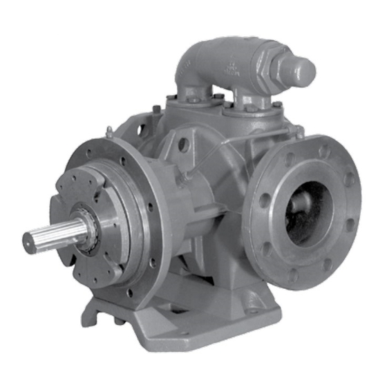
figure 1
Model KKe4076M
(Shown with relief valve on pump casing
and flange mounted bracket - M Drive)
figure 2
Model LQe4176
(Shown with relief valve on pump casing
and foot mounting)
•
•
Cedar Falls, IA 50613 USA
Cedar Falls, IA 50613 USA
SECTION
TSM 710
PAGE
1 Of 8
ISSUE
D
Advertisement
Table of Contents

Related Manuals for Idex Viking Pump 4076 Series


Summary of Contents for Idex Viking Pump 4076 Series
-
Page 1: Table Of Contents
(Shown with relief valve on pump casing TabLe 1 and foot mounting) • • • • VIKING PUMP, INC. VIKING PUMP, INC. A Unit of IDEX Corporation A Unit of IDEX Corporation Cedar Falls, IA 50613 USA Cedar Falls, IA 50613 USA... -
Page 2: Safety Information
SafeTy iNfOrMaTiON aND iNSTruCTiONS iMPrOPer iNSTaLLaTiON, OPeraTiON Or MaiNTeNaNCe Of PuMP May CauSe SeriOuS iNJury Or DeaTh aND/Or reSuLT iN DaMage TO PuMP aND/Or OTher eQuiPMeNT. viKiNg’S WarraNTy DOeS NOT COver faiLure Due TO iMPrOPer iNSTaLLaTiON, OPeraTiON Or MaiNTeNaNCe. ThiS iNfOrMaTiON MuST be fuLLy reaD befOre begiNNiNg iNSTaLLaTiON, OPeraTiON Or MaiNTeNaNCe Of PuMP aND MuST be KePT WiTh PuMP. -
Page 3: Special Information
SPeCiaL iNfOrMaTiON PRESSURE RELIEF VALVES: Relief valves are mounted on the casing. Pumps not furnished with a relief valve must be provided with DaNger ! some means of pressure protection (inline pressure relief before opening any viking pump liquid valve, torque limiting device, or rupture disk). chamber (pumping chamber, reservoir, If pump rotation is to be reversed during operation, pressure relief valve adjusting cap fitting, etc.) -
Page 4: Disassembly
DiSaSSeMbLy baLL beariNg DaNger ! beariNg hOuSiNg before opening any viking pump liquid chamber (pumping chamber, reservoir, SeTSCreW iNNer relief valve adjusting cap fitting, etc.) SPaCer be sure: OuTer COLLar SPaCer ShafT 1. That any pressure in the chamber has COLLar haLf rOuND riNgS... - Page 5 figure 6 exPLODeD vieW Of viKiNg SerieS 4076 / 4176 PuMPS iTeM NaMe Of ParT iTeM NaMe Of ParT Locknut Relief Valve Lockwasher O-Ring For Relief Valve / Cover Plates End Cap Casing Bushing Lip Seal (2-Req’d) Capscrews For Relief Valve / Cover Plate (8-Req’d) Bearing Spacer Collar (Outer) Cover Plates (2-Req’d) Ball Bearing - KE & KKE / Roller Bearing - LQE (2-Req’d) Rotor and Shaft Assembly Bearing Spacer Collar (Inner) Idler and Bushing Assembly Half Round Ring (2-Req’d) Idler Bushing Nylon Slug (2-Req’d) O-Ring For Head Setscrew, M8 - 1.25 x 8 mm (2-Req’d) Lube Pin Setscrew, M8 - 1.5 x 14 mm (2-Req’d) Head and Lube Idler Pin Assembly Bearing Housing Pipe Plug, Hex Head, 1/4” BSP...
-
Page 6: Assembly
aSSeMbLy NOTe: To facilitate assembly, place the pump casing so that it is standing on one of its flanges with a block of wood under the mounting flange. See FIGURE 5. Install the casing bushing. See “iNSTaLLaTiON Of CarbON graPhiTe buShiNgS” on page 6. See figure 8, and notes under “MeChaNiCaL SeaL”... -
Page 7: Thrust Bearing Adjustment
iNSTaLLaTiON Of fOOT O-riNg Series 4176 pumps come equipped with a removable mounting foot. Removal of the foot is not normally required for maintenance. In cases where the foot needs to be replaced CaPSCreW or is being added, use the following steps. SeaL Ensure alignment pins are installed in the top of the foot PLaTe... -
Page 8: Relief Valve Pressure Adjustment
7. Valve Spring 3. Lock Nut 8. Poppet 4. Spring Guide 9. Cap Gasket 5. Bonnet 10 Bonnet Gasket • • © 3/2013 Viking Pump Inc. VIKING PUMP, INC. A Unit of IDEX Corporation Cedar Falls, IA 50613 USA All rights reserved...