Advertisement
Quick Links
TM
BS-GU2016
User Manual
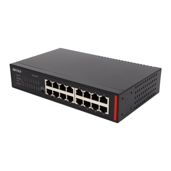
Package Contents
The package contains the items shown below. If any items are missing,
please contact the dealer where you purchased the BS-GU2016.
The appearance of the BS-GU2016 may vary from the illustration.
• Switch (main unit) ................................................................................................... 1
• Power cable (AC 100-240 V) ................................................................................. 1
• Power cable retainer band .................................................................................... 1
• Rubber feet ............................................................................................................... 4
• Mounting brackets................................................................................................... 2
• Screws for mounting brackets ........................................................................... 8
• Serial number stickers............................................................................................. 2
• User manual (this document) .............................................................................. 1
• Warranty ..................................................................................................................... 1
Loop prevention switch
This switches loop prevention
on and o .
LAN ports
These are ports for connecting 1000BASE-
T/100BASE-TX/10BASE-T devices.
Indicators
1.
2.
3.
4.
1. Link/Act (Green)
On:
Link established
Blinking:
Data transfer
If a loop is blocked, the LED for the blocked port
blinks once per second.
O :
Link not established
2. 1000 Mbps (Green)
On:
1000 Mbps link
Blinking:
If a loop is blocked, the LED for the blocked port
blinks once per second.
O :
100 Mbps or 10 Mbps link, no link
3. Loop (Red)
Blinking:
Loop blocked (blinks once per second)
O :
Normal
4. Power (Green)
On:
Power on
Off:
Power off
Layout
Power connector
Connect the included power cable to
this connector.
Power cable
retainer band
Precautions for Installation
• Do not install the device in an unstable location such as on an unsteady
table or an inclined surface.
• Do not place another hub or object that generates heat on this unit.
• Please route all cables properly to prevent people from tripping over
them.
• Ensure the air vents on the product are not blocked by other
equipment or walls.
• Only use the power cable included with the product. Using other
power cables may result in damage or re.
Floor or Shelf Mounting
Attach the supplied rubber feet to the bottom corners of the unit before
use.
Mounting to a Metal Surface
To mount to a metal surface, such as the side of a steel desk, use the
"BS-MGK-A Magnet Kit" (sold separately). Attach the supplied rubber feet
to the bottom corners of the unit before using the magnet kit.
Caution: Do not put floppy discs, magnetic cards, or other magnetic
storage media near magnets. Doing so may delete or corrupt
data.
Note:
If the switch is secured by the magnet alone, it should be no
more than 75 cm (29.5 in) from the floor.
Mounting to a Wall
The BS-GU2016 can be mounted to a wall using the supplied mounting
brackets or the mounting holes on the bottom.
To mount the unit with the mounting brackets, install as shown in the
gure below.
To mount the unit directly to the wall, use 2 screws (not included) with the
IN
A C
dimensions shown below. Install the screws 85 mm (3.3 in) apart and slide
the mounting holes on the base of the BS-GU2016 over them.
Mounting bracket
Mounting screws
(right and left: 2 each)
Installing on 19-inch Rack
Install as shown in the gure below by using the supplied mounting
brackets.
Mounting bracket
19-inch rack screws (not included)
(right and left: 2 locations)
Installation
Screws (not included)
(right and left: 2 each)
Screws (not included)
2mm
Mounting screws (right and left: 4 each)
Advertisement

Related Manuals for Buffalo BS-GU2016


Summary of Contents for Buffalo BS-GU2016
- Page 1 Mounting to a Wall This switches loop prevention Connect the included power cable to The BS-GU2016 can be mounted to a wall using the supplied mounting on and o . this connector. brackets or the mounting holes on the bottom.
- Page 2 ・ Loop prevention cannot detect or block all types of loops. (excluding protruding parts) Turning Loop Prevention On and Off Weight 1.1 kg (2.43 lb.) Use the switch on the front of the BS-GU2016 to turn loop prevention on Operating Operating temperature: 0–50 ℃ (32-122 °F) or o . Environment Operating humidity: 10–85 % (no condensation)