Advertisement
Quick Links
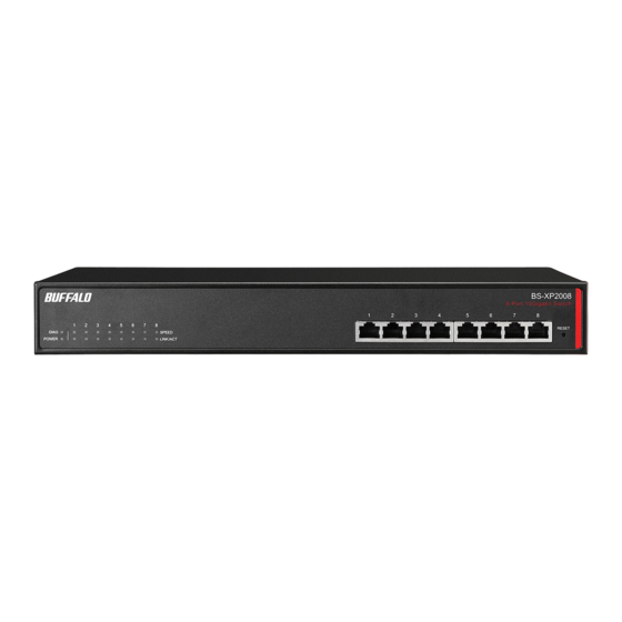
BS-XP2008/BS-XP2012
日本語
クイックセットアップガイド
パッケージ内容
本製品には、 以下のものが同梱されています。
□スイッチ (本製品) ............................................................1台
□ラック固定用ネジ ............................................................4本
□電源ケーブル
□電源ケーブル抜け防止バンド.....................................1個
日本 ・ アメリカ向けの場合.............................................1本
□ゴム足 .................................................................................4個
ヨーロッパ向けの場合...................................................2本
□シリアルNo シール..........................................................2枚
□3ピン−2ピン変換コネクター
□クイックセッ トアップガイド ..........................................2枚
(アース線付き、 日本向け) ............................................1個
□安全にお使いいただくために必ずお守りください
□19インチラック取り付け金具.......................................2個
(保証書付き、 日本向け) ................................................1枚
□取り付け金具固定用ネジ..............................................8本
各部の名称とはたらき
前面
③
④
BS-XP2008
①
②
③
④
⑤
BS-XP2012
①
②
⑦
背面
① DIAGランプ
⑤ LANポート
点灯 (緑) : 通常状態
他のハブやスイッチを接続する、
点灯 (赤) : 起動中、 自己診断または
10GBASE-T / 1000BASE-T /
初期化の実行中
100BASE-TXポートです。 通信速度は
1秒間隔で点滅 (赤) : ループ検知時
自動的に認識されます。
1秒間に複数回点滅 (赤) : ファンの
PoE給電には対応していません。
エラー時
⑥ RESETボタン
② POWERランプ
本製品の電源を入れた状態で、
点灯 (緑) : 電源がONの状態
DIAGランプが赤く点灯するまで (約3
消灯 : 電源がOFFの状態
秒間) ボタンを押し続けると、 本製品
の設定が出荷時の状態に戻ります。
③ SPEEDランプ
点灯 (緑) : 10Gリンク確立時
⑦ AC端子
点灯 (橙) : 1000Mリンク確立時
付属の電源ケーブルを接続します。
消灯 : 100Mリンク確立時、
またはリンク未確立時
⑧ 電源ケーブル抜け防止バンド取り付
※ループ検知時には、 ループが検知
け穴
されたポートのランプが1秒間隔
付属の電源ケーブル抜け防止バンド
で点滅します。
を取り付けます。
④ LINK/ACTランプ
電源ケーブル抜け防止バンドにケー
点灯 (緑) : リンク確立時
ブルを引っかけることで、 ケーブルの
点滅 (緑) : データ送受信時
抜けを防止できます。
消灯 : リンク未確立時
※ループ検知時には、 ループが検知
されたポートのランプが1秒間隔
で緑色に点滅します。
1、 ビジネススイッチ設定ツールをインストールする
ビジネススイッチ設定ツールを使用すると、 簡単に設定画面にアクセスできます。
1
インターネッ トに接続している管理者パソコン (Windows) を起動します。
2
下記URLにアクセスし、 「 ビジネススイッチ設定ツール」 をダウンロードします。
BS-XP2008: http://d.buffalo.jp/bs-xp2008/
BS-XP2012: http://d.buffalo.jp/bs-xp2012/
3
ダウンロードしたファイルをダブルクリックします。
4
以降は画面に従ってインストールしてください。
BS-XP2008/BS-XP2012
English
Quick Setup Guide
Package Contents
□Main unit....................................................................................... 1
□19-inch rack metal fittings screw......................................... 8
□AC cable
□Screw for 19-inch rack.............................................................. 4
The number of AC cable differs depending on your region.
□Power cable retaining band................................................... 1
US, Japan ...................................................................................... 1
□Rubber feet .................................................................................. 4
EU .................................................................................................... 2
□S/N label........................................................................................ 2
□3pin to 2pin connecter
□Quick setup guide ..................................................................... 2
(For Japan only; not usable for US/EU users)................... 1
□Warranty statement.................................................................. 1
□19-inch rack metal fittings ..................................................... 2
Diagrams and Layout
Front
BS-XP2008
3
4
1
2
3
4
5
BS-XP2012
1
2
7
Rear
1. Diag LED
4. Link/Act LEDs
On (green): The switch is in normal
On (green): Link established.
operating condition.
Blinking (green): Transmitting data, or
On (red): Booting, executing
a loop has been detected. (Blinks
self-diagnostic, or initializing.
once per second)
Blinking (red): A fan error occurred.
Off: "Link not established.
(Blinks multiple times per second)
Slow blinking (red): Loop detected.
5. LAN ports
(Blinks once per second)
Connect hubs or switches to these
ports.
2. Power LED
These ports don't support PoE.
On (green): Power is on.
Off: Power is off.
6. Reset Button
Press and hold this button for 3
3. Speed LEDs
seconds to initialize the switch.
On (green): 10 Gbps link.
On (amber): 1000 Mbps link.
7. Power Connector
Blinking: Loop detected. (Blinks once
Connect the included AC cable to this
per second)
connector.
Off: 100 Mbps link or no link.
8. Power cable retaining band's hole
Attach the power cable retaining
band here.
Secure the AC cable with the included
retaining band.
1. Install Business Switch Configuration Tool
Install "Business Switch Configuration Tool" to access Settings easily.
1
Boot your Windows PC connected to the Internet.
2
Access the following URL and download the "Business Switch Configuration Tool".
BS-XP2008: http://d.buffalo.jp/bs-xp2008/
BS-XP2012: http://d.buffalo.jp/bs-xp2012/
3
Double-click the file. Open the folder and double-click "BSSet2_Setup.exe".
4
Follow the installer screens.
□Warranty Statement (アメリカ ・ ヨーロッパ向け) ....1枚
□Lifetime Warranty (アメリカ向け) ...........................1枚
※本製品の保証書は、 本製品の修理をご依頼いただく
場合に必要となりますので、 大切に保管してください。
※追加情報が別紙で添付されている場合は、 必ず参照し
てください。
2、 スイッチを設置する
1
本製品を設置する場所を決め、 以下の手順に従って設置してください。
■平らな場所に設置する場合
本製品底面に付属のゴム足4個を取り付けてください。
・ AC電源に近い平らな場所に本製品を置き、 本製品の周囲に通気のためのスペー
スを5cm以上確保します。
⑥
注意
・ 本製品の上に他の装置を積み重ねないでく ださい。
■19インチラッ クに設置する場合
付属の19インチラック取り付け金具、 取り付け金具固定用ネジ、 ラック固定
用ネジを使用してください。
⑧
・ ラッ ク内の温度は室温よ り高く なりやすいため、 ラッ ク環境の温度が指定された動
作温度範囲であるこ とを確認してく ださい。
注意
・ ラッ クに取り付けた装置の上に他の装置を積み重ねないでく ださい。
・ ラッ クに電力を供給する回路が過負荷にならないようにしてく ださい。
・ ラッ クに取り付けた装置は、 適切にアースされていなければなりません。 供給電源
接続時は、 主電源への直接接続時以上に注意してく ださい。
1
付属の取り付け金具固定用ネジ
で金具を本製品の左右側面に取
り付けます。 底面にゴム足を取り
付けている場合は、 取り外してく
ださい。
2
ラック固定用ネジ4本で、 本製品を
ラックや壁に固定します。
■壁に設置する場合
右図のような市販のネジ2本を、 137mmの間隔で
壁に固定し、 底面の壁掛け用の穴を引っかけてくだ
さい。
■スチール製デスクの側面に設置する場合
本製品底面の四隅に、 別売のマグネッ トキッ ト 「BS-MGK-A」 を取り付けて設
置してください。
非スチール素材の場所へ設置する場合は、 別売のマグネッ ト取り付け用金
具 「LSW-KG5P」 をご使用ください。 ( 日本向けの場合のみ)
2
付属の電源ケーブルを、 本製品およびコンセントに接続します。
ACコンセン トが2ピンのときは、 付属の3ピ
ン−2ピン変換コネクターを使ってコンセン
注意
トに接続します。 感電防止のため、 アース線
は必ず接地してく ださい。
アース線は電源プラグをつなぐ前に接続し、
電源プラグを抜いてから外してく ださい。 順
序を守らないと感電の原因となります。 アー
ス線がコンセン トや他の電極に接触しない
ようにしてく ださい。
3
前面パネルのPOWERランプが点灯していることを確認します。
□Lifetime Warranty (For US only)............................................ 1
□Japanese manuals (For Japan only) .................................... 3
- Keep the warranty statement at hand to request covered
repairs.
- Unless clearly permitted in the product documentation,
do not use accessories (such as cables) other than those
included in the package with this product.
2. Installation
1
Decide where to install the switch and follow the procedure below.
Floor or Shelf Mounting
Attach the included rubber feet to the bottom corners of the unit before use.
Notes:
- Place the switch on a flat surface near the AC inlet. Set it more than 5 cm (2
inches) from the wall for aeration.
6
- Do not stack another device on top of the switch.
Installing on the 19-Inch Rack
Install as shown in the figure below by using the included mounting
brackets.
8
Notes:
- Confirm that the temperature inside of the rack is within range of the operating
environment.
- Do not stack another device on top of the switch installed on the rack.
- Do not let the power supply circuit of the rack overload.
- Make sure that the switch installed on the rack is grounded.
1
Install metal fittings on the switch
by using screws for the 19-inch
rack. Remove rubber feet if
attached.
2
Use 4 metal fittings screws to fix the
switch onto the rack.
Wall Mounting
To mount the unit onto a wall, use 2 screws (not included) with the
dimensions shown below. Install the screws 137mm (5.4 in) apart and slide
the mounting holes into the base of the switch over them.
Use screws where this section is 2 mm
(0.08 in) or less.
2 mm (0.08 in)
φ6 mm (0.24 in)
3mm (0.12 in)
Mounting to a Metal Surface
To mount to a metal surface on a steel desk, use the "BS-MGK-A Magnet Kit"
(sold separately).
Notes:
- Do not put floppy discs, magnetic cards, or other magnetic storage media near
magnets. Doing so may delete or corrupt data.
- Never put anything near the fan.
2
Connect the power cable to the switch.
3
Confirm that the power LED is on.
3、 設定画面を表示する
本製品の設定画面にアクセスすると、 本製品の設定変更や状態の確認ができます。
2016.10
1
LANケーブル (別売) で、 本製品を管理者パソコンおよび既存のネッ トワーク環
境 (社内ネッ トワーク) に接続します。
ケーブルを接続したポートのLINK/ACTランプが点灯することを確認してくださ
い。
2
デスク トップ上の 「ビジネススイッチ設定ツール」 を
ダブルクリックします。
3
[次へ] をクリックして、 スイッチの検索を開始します。
4
本製品を選択して、 [ 次へ] をクリックします。
5
[このスイッチのIPアドレスを設定する] をクリックします。
6
管理者パソコンのIPアドレスと同じセグメントになるように、 本製品のIPアドレ
1
スを設定し、 [ 次へ] をクリックします。 パスワード入力画面が表示されたら、
「password」 ( 小文字) を入力して [次へ] をクリックします。
金具固定用
ネジ (付属品)
2
ラック固定用ネジ (付属品)
2
7
[スイッチ選択画面に戻る] をクリックした後、 もう一度本製品を選択し、 [ 次へ]
− [設定画面を開く] をクリックします。
8
[OK] をクリックするとブラウザーが起動し、 ログイン画面が表示されます。
ユーザー名に 「admin」 ( 小文字) 、 パスワードに 「password」 ( 小文字) を入力し
て、 [ ログイン] をクリックします。
3ピン−2ピン
9
本製品の設定画面が表示されます。 「 ユーザーズマニュアル」 を参照して、 各種
変換コネクター
設定を行ってください。
「ユーザーズマニュアル」 は、 当社ホームページの下記URLよりダウンロードす
ることができます。
BS-XP2008: http://d.buffalo.jp/bs-xp2008/
BS-XP2012: http://d.buffalo.jp/bs-xp2012/
3. Open Settings
Access Settings to change or confirm your switch's settings.
1
Connect the switch to your PC and your network with an Ethernet cable (sold
separately). Confirm that link/act LED of the connected port is on.
2
Double-click the (
) icon to open Business Switch
Configuration Tool.
3
Click Next to start searching for the switch.
4
Select the switch and click Next.
5
Click Change IP Address.
1
6
Configure the switch's IP address to match the segment of the IP address of your
Screws for
PC and click Next. If the password input screen is displayed, enter "password" and
19-inch rack
click Next.
2
Metal fittings screws
7
Click Back to Select Switch and select the switch again; click Next, then click
Settings (Web Admin Interface).
8
Click OK to launch a web browser and display the login screen.
Enter "admin" as the username and "password" as the password, then click Log In.
9
Settings will be displayed. To configure switch settings, refer to user manual. The
user manual can be downloaded from the URLs below.
BS-XP2008: http://d.buffalo.jp/bs-xp2008/
BS-XP2012: http://d.buffalo.jp/bs-xp2012/
ユーザー名 / パスワードについてのご注意
本製品に設定したユーザー名やパスワードを忘れると、 設定画面が表示できなくな
ります。 その場合は、 リセッ トスイッチを押すことで、 ご購入時の状態に戻すことがで
きます。
※リセッ トスイッチが無効に設定されている場合は、 当社修理センターに送付いた
だき、 有償修理となります。
仕様 / 出荷時の設定
●仕様
項 目
LANインターフェース
IEEE 802.3u (100BASE-TX)
IEEE 802.3ab(1000BASE-T)
IEEE 802.3an (10GBASE-T)
IEEE 802.3x (Flow Control)
IEEE 802.3az (EEE Idling Stop)
伝送速度
100 Mbps、 1000 Mbps、 10Gbps
スイッチングデータ転送方式 ストア&フォワード
伝送路符号化方式
DSQ128 (10G BASE-T)
8B1Q4/4D-PAM5 (1000 BASE-T)
4B5B/MLT-3 (100 BASE-TX)
アクセス方式
CSMA/CD
データ転送速度
148,810パケッ ト/s ( 100BASE-TX)
(スループッ ト)
1,488,095パケッ ト/s ( 1000BASE-T)
14,880,000パケッ ト/s ( 10GBASE-T)
バッファー容量
2 MB
Jumboフレーム
9,216 Bytes
※ヘッダー 14 Bytes + FCS 4 Bytes含む
アドレステーブル
16,000件 (セルフラーニング)
LANポート数
BS-XP2008 : 8ポート (全ポートAUTO-MDIX対応)
BS-XP2012 : 12ポート (全ポートAUTO-MDIX対応)
適合ケーブル
カテゴリー5以上 2対UTP/STPケーブル(100BASE-TX)
カテゴリー5e以上 4対UTP/STPケーブル(1000BASE-T)
カテゴリー6A以上 4対UTP/STPケーブル(10GBASE-T)
伝送距離
100m
コネクター形状
RJ-45型8極コネクター (シールドタイプ)
電源電圧
AC100V 50/60Hz
消費電力
BS-XP2008 : 最大38W
BS-XP2012 : 最大50W
外形寸法
W330×H44×D230mm
重量
BS-XP2008 : 約2400g
BS-XP2012 : 約2570g
動作環境
0 - 50° C、 10 - 85% (結露しないこと)
取得規格
VCCI Class A、 FCC Class A、 Canada IC Class A、
UL、 cUL、 CE、 CB
●出荷時の設定
項 目
スイッチ名
BS + 本製品のMACアドレス
IPアドレス
192.168.1.254
サブネッ トマスク
255.255.255.0
デフォルトゲートウェイ
0.0.0.0
ユーザー名/パスワード
admin/password
この装置は、 クラスA情報技術装置です。 この装置を家庭環境で使用すると電波妨害
を引き起こすことがあります。 この場合には使用者が適切な対策を講ずるよう要求さ
※ユーザー名およびパスワードは、
れることがあります。
設定画面で変更できます。
万一、 障害が発生したときは次の対策を行ってください。
・ 本製品とテレビやラジオの距離を離してみる。
・ 本製品とテレビやラジオの向きを変えてみる。
■本書の著作権は当社に帰属します。 本書の一部または全部を当社に無断で転載、 複製、
改変などを行うことは禁じられております。
■BUFFALOは、 株式会社メルコホールディングスの商標です。 本書に記載されている他
社製品名は、 一般に各社の商標または登録商標です。 本書では、 、 、 などのマーク
は記載していません。
■本書に記載された仕様、 デザイン、 その他の内容については、 改良のため予告なしに変
更される場合があり、 現に購入された製品とは一部異なることがあります。
Username and Password Notice
Do not lose the switch's username and password, or you will not be able to configure
settings. If you lose the username or password, press and hold the reset button for 3
seconds to initialize all switch settings. If the reset button is disabled, contact Buffalo
technical support.
Technical Specifications
Specifications
Standards
IEEE 802.3u (100BASE-TX)
IEEE 802.3ab(1000BASE-T)
IEEE 802.3an (10GBASE-T)
IEEE 802.3x (Flow Control)
IEEE 802.3az (EEE Idling Stop)
LAN Transmission Rate
100 Mbps, 1000 Mbps, 10 Gbps
Switching Method
Store and forward
Transmission Encoding
DSQ128 (10GBASE-T)
8B1Q4/4D-PAM5 (1000BASE-T)
4B5B/MLT-3 (100BASE-TX)
Access Method
CSMA/CD
148,810 packets/second ( 100BASE-TX)
Throughput
1,488,095 packets/second ( 1000BASE-T)
14,880,000 packets/second ( 10GBASE-T)
Buffer Capacity
2 MB
Jumbo Frame
Up to 9 KB (including 14 byte header + 4byte FCS)
MAC Address Table
16,000
Ports
BS-XP2008: 8 LAN
BS-XP2012: 12 LAN
Compatible Cables
100BASE-TX:RJ-45 connectors;
1000BASE-T:RJ-45 connectors;
10GBASE-T:RJ-45 connectors;
Transmission Distance
100 m
Connector
RJ-45
Power Supply
AC 100-240 V 50/60 Hz
Power Consumption
BS-XP2008: 38 W (Max)
BS-XP2012: 50 W (Max)
Dimensions (W x H x D)
330 x 44 x 230 mm; 12.99 x 1.73 x 9.06 in
Weight
BS-XP2008: Approx. 2400g; 5.29lb
BS-XP2012: Approx. 2570g; 5.67lb
Operating Environment
0-50°C (32-122°F), 10-85% (non-condensing)
Acquired Standards
VCCI Class A, FCC Class A, Canada IC Class A,
UL, cUL, CE, CB
Default Settings
Switch Name
BS + switch's MAC address
IP Address
192.168.1.254
Subnet Mask
255.255.255.0
Default Gateway
0.0.0.0
Username/Password
admin/password
The socket-outlet shall be installed near the equipment and shall be easily accessible.
Environmental Information
• The equipment that you have purchased has required the extraction and use of natural
resources for its production.
• The equipment may contain hazardous substances that could impact health and the
environment.
• In order to avoid the dissemination of those substances in our environment and to
diminish the pressure on the natural resources, we encourage you to use appropriate
take-back systems.
• The take-back systems will reuse or recycle most of the materials of your end-of-life
equipment.
• The crossed-out wheeled bin symbol invites you to use those systems.
• If you need more information on collection, reuse and recycling systems, please
contact your local or regional waste administration.
仕 様
出荷時設定
two-pair category 5 or higher UTP or STP cable
four-pair category 5e or higher UTP or STP cable
four-pair category 6A or higher UTP or STP cable
Advertisement

Related Manuals for Buffalo BS-XP2008


Summary of Contents for Buffalo BS-XP2008
- Page 1 If you lose the username or password, press and hold the reset button for 3 Connect the switch to your PC and your network with an Ethernet cable (sold seconds to initialize all switch settings. If the reset button is disabled, contact Buffalo separately). Confirm that link/act LED of the connected port is on.
- Page 2 Vérifiez si le voyant link/act du port connecté est bien allumé. bouton de réinitialisation, afin de réinitialiser tous les paramètres du switch. Si le bouton de réinitialisation est désactivé, contactez le support technique de Buffalo. Contenu du package Pour ouvrir l'outil de configuration du switch d'entreprise, double-cliquez sur l'icône (...