
Related Manuals for Omega SP-005


Summary of Contents for Omega SP-005
- Page 1 User’s Guide Shop online at omega.com e-mail: info@omega.com For latest product manuals: www.omegamanual.info SP-005 Thermocouple and RTD Smart Probe P a g e...
- Page 2 Tel: (203) 359-1660 Fax: (203) 359-7700 e-mail: info@omega.com The information contained in this document is believed to be correct, but OMEGA accepts no liability for any errors it contains and reserves the right to alter specifications without notice. P a g e...
-
Page 3: Table Of Contents
Thermocouple Interface ...........................9 4.3.1 Cold Junction Calibration ........................... 10 RTD Interface ..............................11 Setting Alarms ..............................11 ON/OFF Control ............................. 12 Appendix: SP-005 Registers........................13 Thermocouple Descriptor ..........................13 5.1.1 Thermocouple Measurement Type ........................13 5.1.2 Thermocouple Input Data Type/Format ......................14 5.1.2.1... - Page 4 Digital Input / Output Interface ........................18 5.3.1 DIO Descriptor ..............................18 5.3.1.1 DIO Sensor Type ................................18 5.3.1.2 DIO Data Type/Format ..............................19 5.3.1.3 Data Type ..................................19 5.3.1.4 Factory Calibrate ................................19 5.3.1.5 Sensor Writeable ................................19 5.3.1.6 Smart Sensor ...................................
-
Page 5: Notes, Warnings, And Cautions
/ or damage to your equipment. The following labels identify information that is especially important to note: Note: Provides you with information that is important to successfully setup and use the SP-005. Caution or Warning: Tells you about the risk of electrical shock. -
Page 6: Introduction
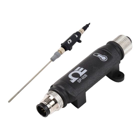
2 Introduction The Layer N SP-005 Thermocouple and RTD Smart Probe provides an easy way to integrate your thermocouple and RTD probes to the Layer N Ecosystem. The SP-005 accepts standard M12 thermocouples and RTDs through its M12 4-pin connector and Layer N Smart Interfaces through its M12 8-pin connector. -
Page 7: Hardware Setup
3 Hardware Setup Connecting your Layer N Smart Interface The SP-005 requires a Layer N Smart Interface to connect to your computer. Use the M12 8-Pin Connector diagram below to connect your SP-005 to your Layer N Smart Interface. Name... -
Page 8: Sync Configuration
SYNC is available to download for free on the OMEGA website. Connecting to SYNC - Automatic Detect Once the SP-005 and Layer N Smart Interface are connected to your computer, SYNC will automatically detect it and begin displaying temperature readings. -
Page 9: Thermocouple Interface
Once you have completed setting the communication parameters for your device, click Finish. Thermocouple Interface The SP-005 provides interfaces to type J, K, T, E, N, R, S, B and C thermocouples with the capability of enabling or disabling the open detect feature. To use these features, follow these steps: Step 1: Click the Inputs configuration tab on SYNC and choose your input type from the Type dropdown. -
Page 10: Cold Junction Calibration
4.3.1 Cold Junction Calibration The SP-005 has automatic Cold Junction Compensation and is factory calibrated so that in most cases it needs no adjustment. If increased accuracy is desired, Cold Junction Calibration can be performed as described below: Step 1: Ensure your thermocouple has been configured in the previous section and click Calibration beneath the input interface. -
Page 11: Rtd Interface
RTD Interface The SP-005 supports 100, 500, and 1000 ohm Platinum RTD sensors in 2, 3, and 4-wire configurations. To use these features, follow these steps: Note: A single RTD connection is supported. Step 1: Click the Inputs Configuration Tab on SYNC and choose your input type from the Type dropdown. -
Page 12: On/Off Control
ON/OFF Control To configure ON/OFF Control on a device, navigate to the Output Configuration Tab in SYNC and click on the icon located to the right of the available outputs. Clicking the icon will open Define ON/OFF Control dialog box as seen below. Choose the input with the active alarm that you would like to control and set your preferred parameters. -
Page 13: Appendix: Sp-005 Registers
5 Appendix: SP-005 Registers The following Appendix provides the registers and list index for the Layer N SP-005 Thermocouple and RTD Smart Probe. This information is intended to aid users who will be making configurations and adjustments to their Layer N SP-005 Thermocouple and RTD Smart Probe through the Command Line Interface or other custom interfaces. -
Page 14: Thermocouple Input Data Type/Format
5.1.2 Thermocouple Input Data Type/Format The SP-005 supports extended configuration and provides factory calibration. All data values are returned as 32-bit floating point values. Thermocouple Input Data Type Smart Sensor Factory Reserved Data Type Sensor Writeable Calibrate 5.1.2.1 0x06 == FLOAT Data Type The 4-bit Data Type field determines the type of data of the specific sensor. -
Page 15: Lock
5.1.3.3 Lock If set, the user specified units of measure string (4-character maximum) will be used in place of the default units of measure. 5.1.3.4 Assigned Refer to the Smart Sensor Device Interface documentation. 5.1.3.5 Available Refer to the Smart Sensor Device Interface documentation. 5.1.4 Thermocouple Device Byte The Sensor Device byte determines whether the Open Circuit detection is enabled. -
Page 16: Rtd Descriptor
Measurement Units 0x21 °C RTD Temperature 5.2.2 RTD Input Data Type/Format The SP-005 supports extended configuration and provides factory calibration. All data values are returned as 32-bit floating point values. RTD Input Data Type Smart Sensor Factory Reserved Data Type... -
Page 17: Smart Sensor
5.2.2.5 Smart Sensor Refer to the Smart Sensor Device Interface documentation. 5.2.3 RTD Configuration RTD Configuration Available Assigned Apply Lock Sensor Type (Range) Scaling 5.2.3.1 See Below Sensor Type / Range Sensor Type Sensor Input Type (Range) Measurement Type 0x00 100 Ohm, 385 Curve 0x21 Temperature (°C) -
Page 18: Rtd Ipso Definition
5.2.6 RTD IPSO Definition The RTD sensor IPSO definition provides signal range, measured min/max values, IPSO object type information. The Min / Max range values depend on the type of RTD. Offset Name Value Description 0x00 Sensor Type 3303 Temperature (°C) 0x02 Precision Provides reading of xxx.x... -
Page 19: Dio Data Type/Format
5.3.1.2 DIO Data Type/Format DIO Data Type Smart Sensor Sensor Writable Factory Calibrate reserved Data Type 6 == Floating point Note: Please refer to the Smart Sensor Interface Technical Guide for more information regarding this descriptor. 5.3.1.3 Data Type The 4-bit Data Type field determines the type of date of the specific sensor. 5.3.1.4 Factory Calibrate The Factory Calibrate bit is not used for DIO types. -
Page 20: Dio Device Configuration
5.3.3 DIO Device Configuration The DIO Device Configuration allows enabling each of the 2 input bits and selecting whether the input is active HIGH or active LOW. If the Invert Bit is set the signal will be Active Low. DIO Device Configuration Reserved DIN 1 DIN 0... -
Page 21: Dio Input Circuitry
5.3.5 DIO Input Circuitry The DIO input circuitry shares the output circuitry. The internal processor drives the Output Control signal to turn on the output driver which will force the output LOW. When the state of the DIO input signal is to be read the processor applies 3.0 V to the Input Bias signal and reads the level detected at the Input Sense. -
Page 22: Outputs
DIN signal to override and read back the state of the output signal. Output Type The SP-005 probe supports NULL (0), ON/OFF (1) or PWM (2) outputs. When set to NULL the output signal will be left in a high impedance state. When set to ON/OFF the Rate information has no affect. -
Page 23: Specifications
6 Specifications INPUT POWER Voltage: 2.8 V - 3.3 V DIO DIGITAL INPUTS = 2.2 V inHighThreshold = 0.3 V inLowThreshold = 30 V inMAX DIO DIGITAL OUTPUTS 2x Open Drain 100 mA max = 30 V ENVIRONMENTAL Operating Temperature: -40 to 850°C (-40 to 185°F) Rating: IP67 when mated MECHANICAL Dimensions: 22.1 mm W x 96.7 mm L (0.87”... - Page 24 Department will issue an Authorized Return (AR) number immediately upon phone or written request. Upon examination by OMEGA, if the unit is found to be defective, it will be repaired or replaced at no charge. OMEGA’s WARRANTY does not apply to defects resulting from any action of the purchaser, including but not limited to mishandling, improper interfacing, operation outside of design limits, improper repair, or unauthorized modification.
- Page 25 Where Do I Find Everything I Need for Process Measurement and Control? OMEGA…Of Course! Shop online at omega.com TEMPERATURE M U Thermocouple, RTD & Thermistor Probes, Connectors, Panels & Assemblies M U Wire: Thermocouple, RTD & Thermistor M U Calibrators & Ice Point References M U Recorders, Controllers &...