
Related Manuals for Epson UB-U09


Summary of Contents for Epson UB-U09
- Page 1 Confidential Developer’s Guide USB/Serial interface board UB-U09 Issued date Issued by English 4014379 EPSON...
- Page 2 EPSON SEIKO EPSON CORPORATION Printed in Japan...
- Page 3 ❏ On the earlier of (a) termination of your relationship with Seiko Epson, or (b) Seiko Epson’s request, you must stop using the confidential information. You must then return or destroy the information, as directed by Seiko Epson.
-
Page 4: Table Of Contents
Confidential CONTENTS Meaning of Symbols ........... v Purpose of this Document . -
Page 5: Meaning Of Symbols
Purpose of this Document This document is intended to provide all information necessary for system planning, design, installation and application of the UB-U09 for designers and developers of POS systems. Meaning of Terms ❏ In this document, “Serial communication” means the RS232 compliant serial communication. -
Page 6: Product Servicing
Confidential Product Servicing This product cannot be serviced at the component level. If damage occurs, the UB-U09 should be replaced as a unit. Revision Information Revision Page Altered Items and Contents Rev. A Rev. B 2-2, 2-4 Descriptions of hex mounting screws eliminated. -
Page 7: Chapter 1 System Preparation
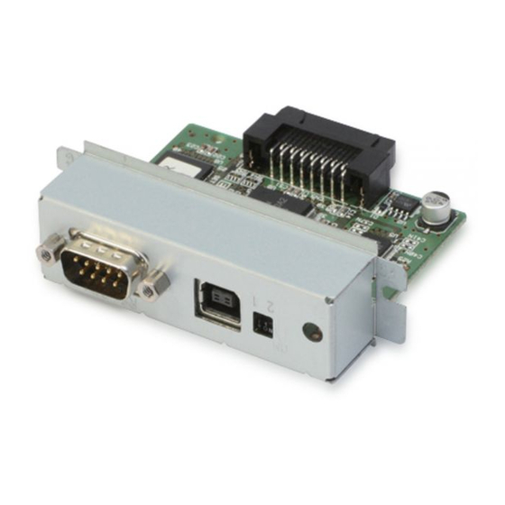
Specifications The UB-U90, which has been developed for EPSON TM Printers, has serial and USB interface functions. You can switch between the functions by using the USB/Serial switching located on the front of the UB-U09. -
Page 8: Interface Cable
Interface Cable Prepare a serial or USB interface cable according to customer requirements. Note that while the standard serial interface of the TM printers uses a 25-pin D-sub connector, the UB-U09 uses a 9-pin D-sub connector. Table 1-1 shows the recommended wiring for the interface cable. -
Page 9: Compatible Printers
JP2 on the UB-U09, causes the printer to be continually reset. Table 1-2 shows the relationship between jumper JP2 on the UB-U09 and “disable reset via pin 6” setting on the TM printer. (*2) To reset the TM printer through the interface, the reset signal can be applied to pin 6 or pin 9. -
Page 10: Temperature/Humidity Conditions
Confidential Temperature/Humidity Conditions Refer to the TM printer and customer display specifications for operating temperature and humidity specifications. 1-4 System Preparation Rev. B... -
Page 11: Chapter 2 Installation
Even when the power switch is off, voltage is present at some points on the circuit board. Changing components while the power unit is connected can cause damage to the UB-U09 and the printer. ❏ A grounded wrist strap should be worn during installation to avoid damage from static electricity. -
Page 12: Package Contents
Confidential Package Contents The following items should be included in the UB-U09 package. You can get a locking wire strain relief separately by using the part numbers in the brackets. ❏ UB-U09 ❏ User’s Manual ❏ Locking wire strain relief <1061268>... -
Page 13: Jumper Locations
Jumper Settings The UB-U09 has a jumper: JP2. JP2 selects the function* of pin 6 (DSR) of the serial connector. (*) Refer to Printer Reset in Chapter 4 for a description of the functions of pin 6 (DSR) of the serial connector. -
Page 14: Circuit Board Installation
1. If an interface circuit board is already installed in the TM printer, remove it. Re-use the screws when installing the UB-U09. Install the UB-U09 using these screws. 2. Install the UB-U09 in the TM printer, and tighten the screws. Install the UB-U09 to using two screws. 2-4 Installation... -
Page 15: Interface Cable Connection
Serial Interface Cable 1. Confirm that the printer and host computer are turned off. 2. Connect the cable to the serial interface connector on the UB-U09. Note: Connect cables that have a smaller shell than the size indicated in the Figure 2-3. If the shell size is bigger, it may not be connected. -
Page 16: Usb Interface Cable
2. Hook USB cable through the locking wire strain relief to keep them in place. 3. Insert the square connector end of the USB cable into the upstream connector of the UB-U09. 4. Insert the opposite end of the USB cable into the downstream connector of the host computer. -
Page 17: Chapter 3 Software
Confidential UB-U09 Developer's Guide Chapter 3 Software Required Software to use the USB Interface Function of the UB-U90 When using the USB interface function of the UB-U90, you need one of the following drivers. Contact your dealer to find out the compatible printers and how to get the software. -
Page 18: Installing Advanced Printer Driver
Figure 3-1, click Next. Then click Finish in the next window. Figure 3-1 11. While the printer is on, open the device manager. If the [EPSON USB Controller for TM Printer Series] exists on the Universal Serial BUS controllers, the installation is successful. - Page 19 3-2, click Next. Then click Finish on the next window. Figure 3-2 11. While the printer is on, open the device manager. If the [EPSON USB Controller for TM Printer Series] exists on the Universal Serial BUS controllers, the installation is successful.
- Page 20 Confidential 3-4 Software Rev. B...
-
Page 21: Chapter 4 Function Description
Confidential UB-U09 Developer's Guide Chapter 4 Function Description The following functions are available when using the serial interface. Each function is described below. ❏ DTR/DSR control ❏ XON/XOFF control ❏ Printer reset DTR/DSR Control The DTR signal indicates the BUSY/READY status of the TM printer; Space status indicates that the TM printer is READY;... -
Page 22: Xon/Xoff Control
Confidential XON/XOFF Control The XON code is defined as character 11h, and the XOFF code is 13h. A DIP switch on the TM printer selects the handshaking conditions under which it sends the XON and XOFF codes. Table 4-2 TM printer XON/XOFF sending conditions Printer DIP Switch Setting XON/XOFF Sending... -
Page 23: Printer Reset
UB-U09 Developer's Guide Printer Reset The UB-U09 can reset the TM printer through the serial interface by applying a signal to pin 6 or pin 9 of the interface. The reset signal logic can be selected by jumper JP2 on the UB-U09 for resetting using pin 6 (DSR). - Page 24 Confidential 4-4 Function Description Rev. B...